Page 682 of 3641
REAR WINDOW DEFOGGER DOES NOT OPERATE BUT BOTH OF DOOR MIR-
ROR DEFOGGER OPERATE.
DEF-31
< SYMPTOM DIAGNOSIS >
C
DE
F
G H
I
J
K
M A
B
DEF
N
O P
REAR WINDOW DEFOGGER DOES NOT OPERATE BUT BOTH OF DOOR
MIRROR DEFOGGER OPERATE.
Diagnosis ProcedureINFOID:0000000012431784
1. CHECK REAR WINDOW DEFOGGER POWER SUPPLY AND GROUND CIRCUIT
Check rear window defogger power supply and ground circuit.
Refer to DEF-24, "
Component Function Check".
Is the inspection result normal?
YES >> Refer to GI-42, "Intermittent Incident".
NO >> Repair or replace the malfunctioning parts.
Revision: August 2015 2016 Versa Note
cardiagn.com
Page 683 of 3641
DEF-32
< SYMPTOM DIAGNOSIS >
BOTH DOORS MIRROR DEFOGGER DON’T OPERATE BUT REAR WINDOW
DEFOGGER OPERATES
BOTH DOORS MIRROR DEFOGGER DON’T OPERATE BUT REAR WIN-
DOW DEFOGGER OPERATES
Diagnosis ProcedureINFOID:0000000012431785
1. CHECK DOOR MIRROR DEFOGGER FUSE
Check if the following fuse in fuse block (J/B) is blown.
Is the inspection result normal?
YES >> GO TO 2.
NO >> If fuse is blown, be sure to eliminate cause of malfunction before installing new fuse.
2. CHECK BOTH DOOR MIRROR DEFOGGER
1. Check door mirror LH. Refer to DEF-26, "
Component Function Check".
2. Check door mirror RH. Refer to DEF-28, "
Component Function Check".
Is the inspection result normal?
YES >> Check intermittent incident. Refer to GI-42, "Intermittent Incident".
NO >> Repair or replace the malfunctioning parts.
COMPONENT PARTS AMPEREFUSE NO.
Fuse block (J/B) 10A1
Revision: August 2015 2016 Versa Note
cardiagn.com
Page 684 of 3641
DRIVER SIDE DOOR MIRROR DEFOGGER DOES NOT OPERATE.DEF-33
< SYMPTOM DIAGNOSIS >
C
DE
F
G H
I
J
K
M A
B
DEF
N
O P
DRIVER SIDE DOOR MIRROR DEFOGGER DOES NOT OPERATE.
Diagnosis ProcedureINFOID:0000000012431786
1. CHECK DOOR MIRROR DEFOGGER LH
Check door mirror defogger LH.
Refer to DEF-26, "
Component Function Check".
Is the inspection result normal?
YES >> Refer to GI-42, "Intermittent Incident".
NO >> Repair or replace the malfunctioning parts.
Revision: August 2015 2016 Versa Note
cardiagn.com
Page 685 of 3641
DEF-34
< SYMPTOM DIAGNOSIS >
PASSENGER SIDE DOOR MIRROR DEFOGGER DOES NOT OPERATE.
PASSENGER SIDE DOOR MIRROR DEFOGGER DOES NOT OPERATE.
Diagnosis ProcedureINFOID:0000000012431787
1. CHECK DOOR MIRROR DEFOGGER RH
Check door mirror defogger RH.
Refer to DEF-28, "
Component Function Check".
Is the inspection result normal?
YES >> Refer to GI-42, "Intermittent Incident".
NO >> Repair or replace the malfunctioning parts.
Revision: August 2015 2016 Versa Note
cardiagn.com
Page 1047 of 3641
![NISSAN NOTE 2016 Service Repair Manual EM-46
< REMOVAL AND INSTALLATION >[HR16DE]
FUEL INJECTOR AND FUEL TUBE
c. After connecting, check that the connection is secure:
• Visually confirm that the two retainer tabs are connected to thecon NISSAN NOTE 2016 Service Repair Manual EM-46
< REMOVAL AND INSTALLATION >[HR16DE]
FUEL INJECTOR AND FUEL TUBE
c. After connecting, check that the connection is secure:
• Visually confirm that the two retainer tabs are connected to thecon](/manual-img/5/57363/w960_57363-1046.png)
EM-46
< REMOVAL AND INSTALLATION >[HR16DE]
FUEL INJECTOR AND FUEL TUBE
c. After connecting, check that the connection is secure:
• Visually confirm that the two retainer tabs are connected to theconnector.
• With the fuel feed hose not fix ed to the clamp, pull quick con-
nector (A) hard by hand to check that the quick connector (A)
is not disconnected from the centralized underfloor piping (1)
and that the quick connector (1) is securely connected.
9. Installation of remaining components is in the reverse order of removal.
INSPECTION AFTER INSTALLATION
Check on Fuel Leaks
1. Turn ignition switch “ON” (with the engine stopped). With fuel pressure applied to fuel piping, check there are no fuel leaks at connection points. Refer to.
NOTE:
Use mirrors for checking points out of clear sight.
2. Start the engine. With engine speed increased, check again that there are no fuel leaks at connection
points.
• Perform procedures for “Throttle Valve Closed Posi tion Learning” after finishing repairs. Refer to EC-
129, "Description".
• If electric throttle control actuator is replaced, perform procedures for “Idle Air Volume Learning” after
finishing repairs. Refer to EC-130, "
Description".
CAUTION:
Do not touch the engine immediately after stopping, as the engine becomes extremely hot.
PBIC3795E
Revision: August 2015 2016 Versa Note
cardiagn.com
Page 1655 of 3641

EXL-3
C
DE
F
G H
I
J
K
M A
B
EXL
N
O P
FRONT FOG LAMP AIMING ADJUSTMENT ..100
Inspection ............................................................ ..100
Aiming Adjustment Procedure ...............................100
REMOVAL AND INSTALLATION .............102
FRONT COMBINATION LAMP ...................... ..102
Exploded View .................................................... ..102
Removal and Installation .......................................102
Bulb Replacement ........ .........................................102
FRONT FOG LAMP ........................................ ..104
Exploded View .................................................... ..104
Removal and Installation .......................................104
Bulb Replacement ........ .........................................105
DOOR MIRROR TURN SIGNAL LAMP ......... ..106
Removal and Installation .......................................106
Bulb Replacement ........ .........................................106
COMBINATION SWITCH ............................... ..107
Exploded View .................................................... ..107
Removal and Installation .......................................107
HAZARD SWITCH .......................................... ..108
Exploded View .................................................... ..108
Removal and Installation .......................................108
REAR COMBINATION LAMP ........................ ..109
Exploded View .................................................... ..109
Removal and Installation ..................................... ..109
Bulb Replacement .................................................109
HIGH-MOUNTED STOP LAMP ......................111
Exploded View .......................................................111
Removal and Installation .......................................111
Bulb Replacement .................................................111
LICENSE PLATE LAMP .................................112
Exploded View .......................................................112
Removal and Installation .......................................112
Bulb Replacement .................................................112
UNIT DISASSEMBLY AND ASSEMBLY ..113
FRONT COMBINATION LAMP ......................113
Exploded View ..................................................... ..113
Disassembly and Assembly ...................................113
REAR COMBINATION LAMP .........................114
Exploded View .......................................................114
Disassembly and Assembly ...................................114
SERVICE DATA AND SPECIFICATIONS
(SDS) ............... .......................................... .
115
SERVICE DATA AND SPECIFICATIONS
(SDS) ...............................................................
115
Bulb specification ................................................. ..115
Revision: August 2015 2016 Versa Note
cardiagn.com
Page 1737 of 3641

TURN SIGNAL LAMP CIRCUITEXL-85
< DTC/CIRCUIT DIAGNOSIS >
C
DE
F
G H
I
J
K
M A
B
EXL
N
O P
TURN SIGNAL LAMP CIRCUIT
DescriptionINFOID:0000000012432813
The BCM monitors inputs from the combination switch (lighting and turn signal switch) to determine when to
activate the turn signals. The BCM outputs voltage direction to the left and right turn signals during turn signal
operation or both during hazard warning operation. The BCM sends a turn signal indicator request to the com-
bination meter via the CAN communication lines.
The BCM performs the fast flasher operation (fail-safe) if any bulb or harness of the turn signal lamp circuit is
open.
NOTE:
Turn signal lamp blinks at normal speed when using the hazard warning lamp.
Component Function CheckINFOID:0000000012432814
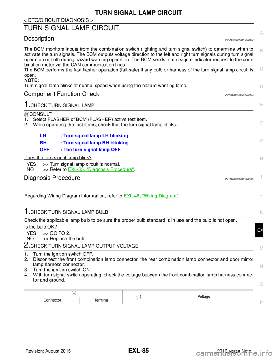
1.CHECK TURN SIGNAL LAMP
CONSULT
1. Select FLASHER of BCM (FLASHER) active test item.
2. While operating the test items, check that the turn signal lamp blinks.
Does the turn signal lamp blink?
YES >> Turn signal lamp circuit is normal.
NO >> Refer to EXL-85, "
Diagnosis Procedure".
Diagnosis ProcedureINFOID:0000000012432815
Regarding Wiring Diagram information, refer to EXL-48, "Wiring Diagram".
1.CHECK TURN SIGNAL LAMP BULB
Check the applicable lamp bulb to be sure the proper bulb standard is in use and the bulb is not open.
Is the bulb OK?
YES >> GO TO 2.
NO >> Replace the bulb.
2.CHECK TURN SIGNAL LA MP OUTPUT VOLTAGE
1. Turn the ignition switch OFF.
2. Disconnect the front combination lamp connector, the rear combination lamp connector and door mirror
lamp harness connector.
3. Turn the ignition switch ON.
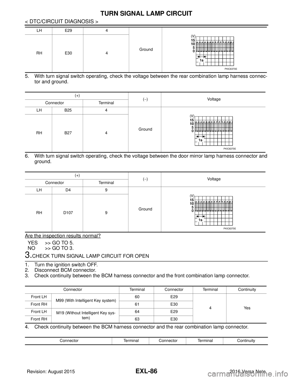
4. With turn signal switch operating, check the vo ltage between the front combination lamp harness connec-
tor and ground. LH : Turn signal lamp LH blinking
RH : Turn signal lamp RH blinking
OFF : The turn signal lamp OFF
(+)
(−) Voltage
Connector Terminal
Revision: August 2015 2016 Versa Note
cardiagn.com
Page 1738 of 3641

EXL-86
< DTC/CIRCUIT DIAGNOSIS >
TURN SIGNAL LAMP CIRCUIT
5. With turn signal switch operating, check the voltage between the rear combination lamp harness connec-tor and ground.
6. With turn signal switch operating, check the vo ltage between the door mirror lamp harness connector and
ground.
Are the inspection results normal?
YES >> GO TO 5.
NO >> GO TO 3.
3.CHECK TURN SIGNAL LAMP CIRCUIT FOR OPEN
1. Turn the ignition switch OFF.
2. Disconnect BCM connector.
3. Check continuity between the BCM harness connector and the front combination lamp connector.
4. Check continuity between the BCM harness connector and the rear combination lamp connector.
LH E29 4
Ground
RH E30 4
(+) (−) Voltage
Connector Terminal
LH B25 4
Ground
RH B27 4
(+) (−) Voltage
Connector Terminal
LH D4 9
Ground
RH D107 9
PKIC6370E
PKIC6370E
PKIC6370E
Connector Terminal Connector Terminal Continuity
Front LH M99 (With Intelligent Key system) 60
E29
4Yes
Front RH
61E30
Front LH M19 (Without Intelligent Key sys-
tem) 64
E29
Front RH 63E30
Connector Terminal Connector Terminal Continuity
Revision: August 2015 2016 Versa Note
cardiagn.com