2016 NISSAN NOTE mirror
[x] Cancel search: mirrorPage 1739 of 3641
TURN SIGNAL LAMP CIRCUITEXL-87
< DTC/CIRCUIT DIAGNOSIS >
C
DE
F
G H
I
J
K
M A
B
EXL
N
O P
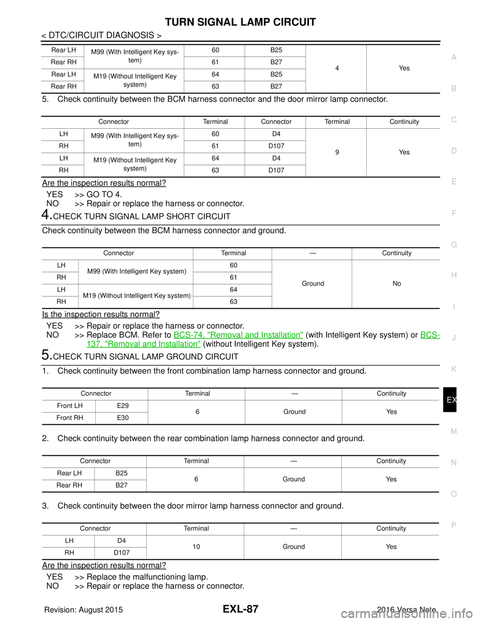
5. Check continuity between the BCM harness connector and the door mirror lamp connector.
Are the inspection results normal?
YES >> GO TO 4.
NO >> Repair or replace the harness or connector.
4.CHECK TURN SIGNAL LAMP SHORT CIRCUIT
Check continuity between the BCM harness connector and ground.
Is the inspection results normal?
YES >> Repair or replace the harness or connector.
NO >> Replace BCM. Refer to BCS-74, "
Removal and Installation" (with Intelligent Key system) or BCS-
137, "Removal and Installation" (without Intelligent Key system).
5.CHECK TURN SIGNAL LAMP GROUND CIRCUIT
1. Check continuity between the front combination lamp harness connector and ground.
2. Check continuity between the rear combination lamp harness connector and ground.
3. Check continuity between the door mirror lamp harness connector and ground.
Are the inspection results normal?
YES >> Replace the malfunctioning lamp.
NO >> Repair or replace the harness or connector.
Rear LH M99 (With Intelligent Key sys-
tem) 60
B25
4Y es
Rear RH
61B27
Rear LH M19 (Without Intelligent Key
system) 64
B25
Rear RH 63B27
Connector Terminal Connector Terminal Continuity
LH M99 (With Intelligent Key sys-
tem) 60
D4
9Y es
RH
61D107
LH M19 (Without Intelligent Key
system) 64
D4
RH 63D107
Connector Terminal—Continuity
LH M99 (With Intelligent Key system) 60
Ground No
RH
61
LH M19 (Without Intelligent Key system) 64
RH 63
ConnectorTerminal —Continuity
Front LH E29
6 Ground Yes
Front RH E30
Connector Terminal —Continuity
Rear LH B25
6 Ground Yes
Rear RH B27
Connector Terminal —Continuity
LH D4
10 Ground Yes
RH D107
Revision: August 2015 2016 Versa Note
cardiagn.com
Page 1758 of 3641
EXL-106
< REMOVAL AND INSTALLATION >
DOOR MIRROR TURN SIGNAL LAMP
DOOR MIRROR TURN SIGNAL LAMP
Removal and InstallationINFOID:0000000012432838
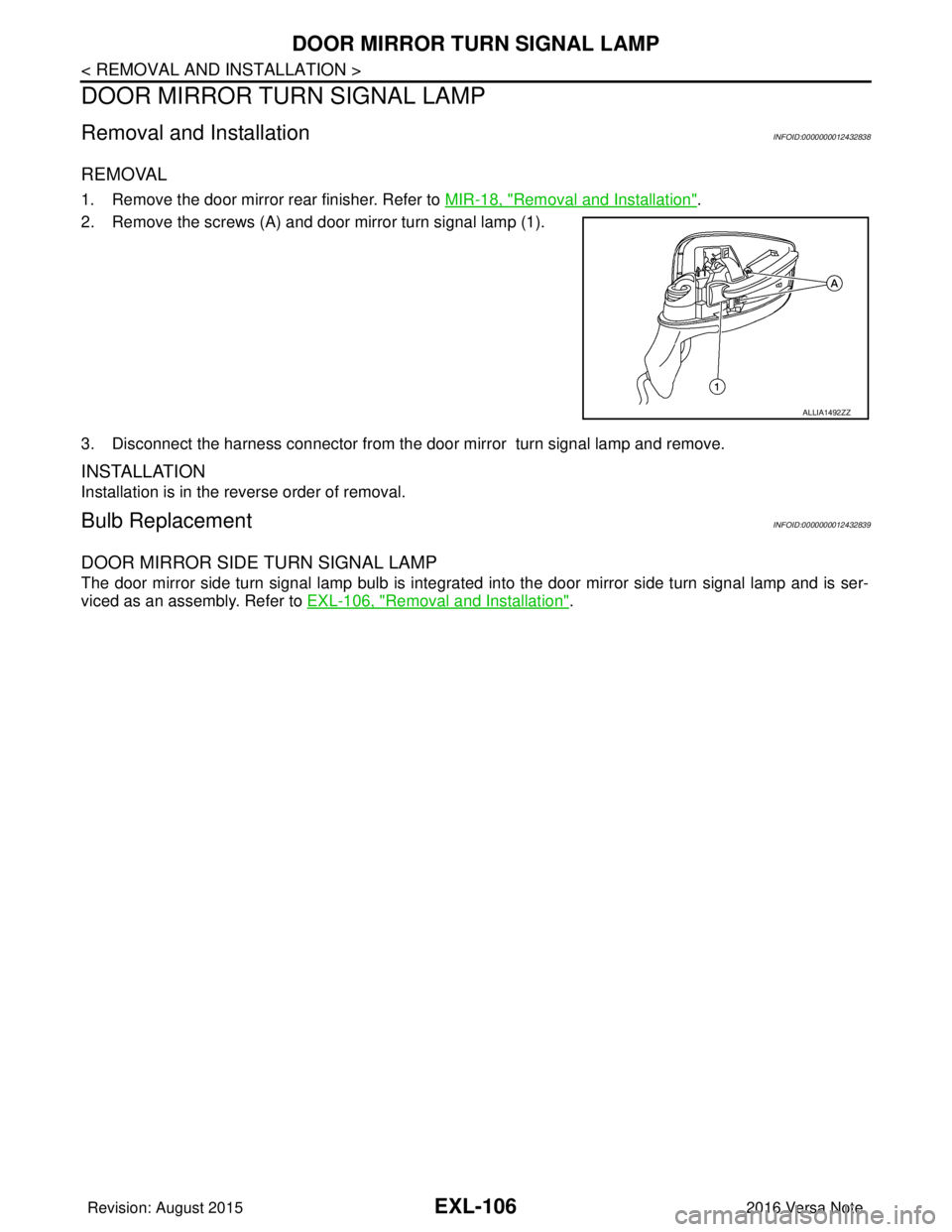
REMOVAL
1. Remove the door mirror rear finisher. Refer to MIR-18, "Removal and Installation".
2. Remove the screws (A) and door mirror turn signal lamp (1).
3. Disconnect the harness connector from the door mirror turn signal lamp and remove.
INSTALLATION
Installation is in the reverse order of removal.
Bulb ReplacementINFOID:0000000012432839
DOOR MIRROR SIDE TURN SIGNAL LAMP
The door mirror side turn signal lamp bulb is integrated into the door mirror side turn signal lamp and is ser-
viced as an assembly. Refer to EXL-106, "
Removal and Installation".
ALLIA1492ZZ
Revision: August 2015 2016 Versa Note
cardiagn.com
Page 1767 of 3641

SERVICE DATA AND SPECIFICATIONS (SDS)EXL-115
< SERVICE DATA AND SPECIFICATIONS (SDS)
C
DE
F
G H
I
J
K
M A
B
EXL
N
O P
SERVICE DATA AND SPECIFICATIONS (SDS)
SERVICE DATA AND SPECIFICATIONS (SDS)
Bulb specificationINFOID:0000000012432857
*: Always check with the Parts Department for the latest parts info.
Item Wattage (W)*
Front combination Headlamp (HI/LO)
65/55
Front Turn signal/Parking lamp 28/8
Side marker lamp 5
Fog lamp (if equipped) 55
Door mirror turn signal lamp (if equipped) LED
Rear combination Stop/Tail lamp
21/5
Rear turn signal lamp 21
Back-up lamp 21
License plate lamp 5
High-mounted stop lamp LED
Revision: August 20152016 Versa Note
cardiagn.com
Page 1910 of 3641

GI-22
< HOW TO USE THIS MANUAL >
RECOMMENDED CHEMICAL PRODUCTS AND SEALANTS
RECOMMENDED CHEMICAL PRODUCTS AND SEALANTS
Recommended Chemical Products and SealantsINFOID:0000000012433157
Refer to the following chart for help in selecting the appropriate chemical product or sealant.
Product Description PurposeNISSAN North America
Part No. (USA) NISSAN Canada Part
No. (Canada) Aftermarket Cross-
reference Part Nos.
1 Rear View Mirror Adhe-
sive Used to permanently re-
mount rear view mirrors to
windows.
999MP-AM000P 99998-50505
Permatex 81844
2 Anaerobic Liquid Gas-
ket For metal-to-metal flange
sealing.
Can fill a 0.38 mm (0.015
inch) gap and provide in-
stant sealing for most pow-
ertrain applications.
999MP-AM001P 99998-50503
Permatex 51813 and
51817
3 High Performance
Thread Sealant Provides instant sealing on
any threaded straight or
parallel threaded fitting.
(Thread sealant only, no
locking ability.)
• Do not use on plastic.
999MP-AM002P 999MP-AM002P Permatex 56521
4 Silicone RTV Gasket Maker999MP-AM003P
(Ultra Grey)99998-50506
(Ultra Grey)Permatex Ultra Grey
82194;
Three Bond
1207,1215, 1216,
1217F, 1217G and
1217H
Nissan RTV Part No.
999MP-A7007
5 High Temperature,
High Strength Thread
Locking Sealant (Red)
Threadlocker
999MP-AM004P 999MP-AM004P Permatex 27200;
Three Bond 1360,
1360N, 1305 N&P,
1307N, 1335,
1335B, 1363B,
1377C, 1386B, D&E
and 1388
Loctite 648
6 Medium Strength
Thread Locking Seal-
ant (Blue) Threadlocker (service tool
removable)
999MP-AM005P 999MP-AM005P Permatex 24200,
24206, 24240,
24283 and 09178;
Three Bond 1322,
1322N, 1324 D&N,
1333D, 1361C,
1364D, 1370C and
1374
Revision: August 2015
2016 Versa Note
cardiagn.com
Page 1952 of 3641
GW-12
< REMOVAL AND INSTALLATION >
WINDSHIELD GLASS
Removal and Installation
INFOID:0000000012430531
REMOVAL
1. Remove front pillar finishers (LH/RH). Refer to INT-21, "FRONT PILLAR FINISHER : Removal and Instal-
lation".
2. Partially remove the headlining (front edge).
3. Remove cowl top cover. Refer to EXT-37, "
Removal and Installation".
4. Remove inside mirror. Refer to MIR-14, "
Removal and Installation".
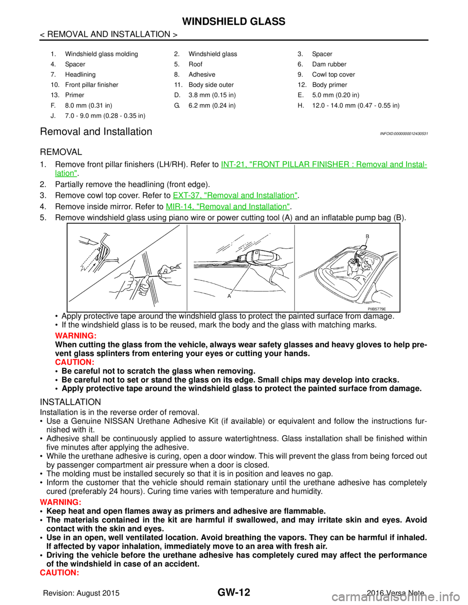
5. Remove windshield glass using piano wire or pow er cutting tool (A) and an inflatable pump bag (B).
• Apply protective tape around the windshield gla ss to protect the painted surface from damage.
• If the windshield glass is to be reused, mark the body and the glass with matching marks.
WARNING:
When cutting the glass from the vehicle, always wear safety glasses and heavy gloves to help pre-
vent glass splinters from entering your eyes or cutting your hands.
CAUTION:
• Be careful not to scratch the glass when removing.
• Be careful not to set or stand the glass on its edge. Small chips may develop into cracks.
• Apply protective tape around th e windshield glass to protect the painted surface from damage.
INSTALLATION
Installation is in the reverse order of removal.
• Use a Genuine NISSAN Urethane Adhesive Kit (if availabl e) or equivalent and follow the instructions fur-
nished with it.
• Adhesive shall be continuously applied to assure watert ightness. Glass installation shall be finished within
five minutes after applying the adhesive.
• While the urethane adhesive is curing, open a door window . This will prevent the glass from being forced out
by passenger compartment air pressure when a door is closed.
• The molding must be installed securely so that it is in position and leaves no gap.
• Inform the customer that the vehicle should remain stationary until the urethane adhesive has completely
cured (preferably 24 hours). Curing time varies with temperature and humidity.
WARNING:
• Keep heat and open flames away as primers and adhesive are flammable.
• The materials contained in the kit are harmful if swallowed, and may irritate skin and eyes. Avoid
contact with the skin and eyes.
• Use in an open, well ventilated location. Avoid breathing the vapors. They can be harmful if inhaled. If affected by vapor inhalation, imme diately move to an area with fresh air.
• Driving the vehicle before the urethane adhesive has completely cured may affect the performance
of the windshield in case of an accident.
CAUTION:
1. Windshield glass molding 2. Windshield glass 3. Spacer
4. Spacer 5. Roof 6. Dam rubber
7. Headlining 8. Adhesive 9. Cowl top cover
10. Front pillar finisher 11. Body side outer 12. Body primer
13. Primer D. 3.8 mm (0.15 in) E. 5.0 mm (0.20 in)
F. 8.0 mm (0.31 in) G. 6.2 mm (0.24 in) H. 12.0 - 14.0 mm (0.47 - 0.55 in)
J. 7.0 - 9.0 mm (0.28 - 0.35 in)
PIIB5779E
Revision: August 2015 2016 Versa Note
cardiagn.com
Page 1961 of 3641
FRONT DOOR GLASS AND REGULATORGW-21
< REMOVAL AND INSTALLATION >
C
DE
F
G H
I
J
L
M A
B
GW
N
O P
FRONT DOOR GLASS AND REGULATOR
Exploded ViewINFOID:0000000012430538
Removal and InstallationINFOID:0000000012430539
WARNING:
• Before servicing, turn the ignition switch off, disconnect both battery terminals and wait at least
three minutes.
• Do not use air tools or electric tools for servicing.
FRONT DOOR GLASS
Removal
1. Disconnect the battery positive and negative terminals then wait at least three minutes. Refer to PG-70,
"Removal and Installation (Battery)".
2. Remove front door finisher. Refer to INT-15, "
Removal and Installation".
3. Remove the vapor barrier. Refer to GW-21, "
Exploded View".
CAUTION:
Use care not to damage or tear vapor barrier during removal.
4. Disconnect the harness connector from the door mirror.
5. Temporarily reconnect both battery terminals and the main power window and door lock/unlock switch (LH
door) or power window and door lock/unlock switch (RH door) to raise/lower the front door glass until the
bolts can be seen through the access holes (with power window).
6. Temporarily reinstall the front door glass handle and raise/lower the front door glass until the bolts can be seen through the access holes (without power window).
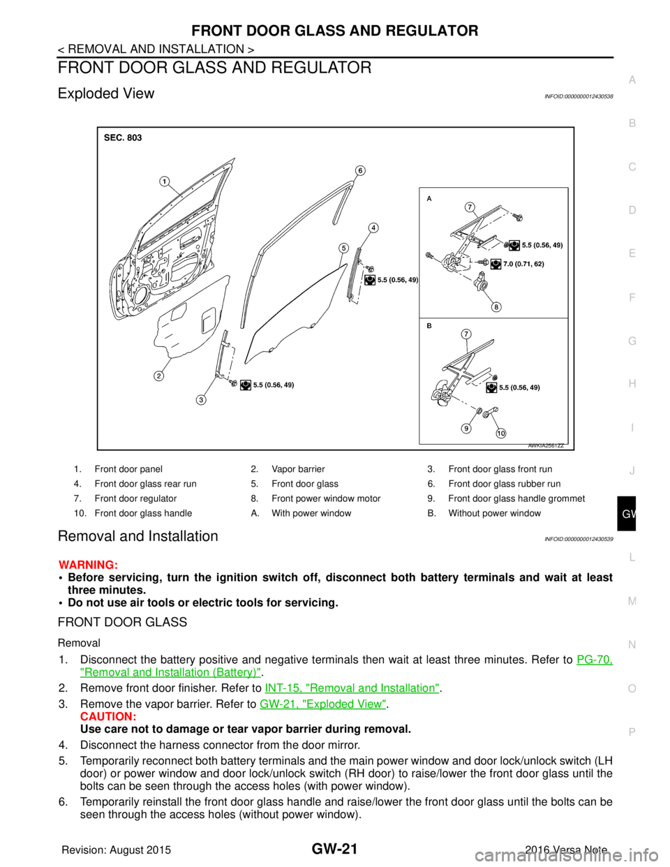
1. Front door panel 2. Vapor barrier3. Front door glass front run
4. Front door glass rear run 5. Front door glass6. Front door glass rubber run
7. Front door regulator 8. Front power window motor9. Front door glass handle grommet
10. Front door glass handle A. With power windowB. Without power window
AWKIA2561ZZ
Revision: August 2015 2016 Versa Note
cardiagn.com
Page 1962 of 3641
GW-22
< REMOVAL AND INSTALLATION >
FRONT DOOR GLASS AND REGULATOR
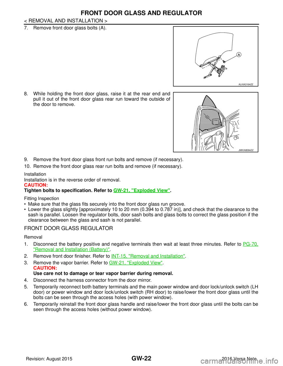
7. Remove front door glass bolts (A).
8. While holding the front door glass, raise it at the rear end andpull it out of the front door glass rear run toward the outside of
the door to remove.
9. Remove the front door glass front run bolts and remove (if necessary).
10. Remove the front door glass rear run bolts and remove (if necessary).
Installation
Installation is in the reverse order of removal.
CAUTION:
Tighten bolts to specification. Refer to GW-21, "
Exploded View".
Fitting Inspection
• Make sure that the glass fits securely into the front door glass run groove.
• Lower the glass slightly [approximately 10 to 20 mm (0.394 to 0.787 in)], and check that the clearance to the
sash is parallel. Loosen the regulator bolts, door sash bolts and glass bolts to correct the glass position if the
clearance between the glass and sash is not parallel.
FRONT DOOR GLASS REGULATOR
Removal
1. Disconnect the battery positive and negative terminal s then wait at least three minutes. Refer to PG-70,
"Removal and Installation (Battery)".
2. Remove front door finisher. Refer to INT-15, "
Removal and Installation".
3. Remove the vapor barrier. Refer to GW-21, "
Exploded View".
CAUTION:
Use care not to damage or tear vapor barrier during removal.
4. Disconnect the harness connector from the door mirror.
5. Temporarily reconnect both battery terminals and the main power window and door lock/unlock switch (LH door) or power window and door lock/unlock switch (RH door) to raise/lower the front door glass until the
bolts can be seen through the access holes (with power window).
6. Temporarily reinstall the front door glass handle and raise/lower the front door glass until the bolts can be seen through the access holes (without power window).
ALKIA3164ZZ
JMKIA8064ZZ
Revision: August 2015 2016 Versa Note
cardiagn.com
Page 2044 of 3641

REFRIGERANTHA-19
< PERIODIC MAINTENANCE >
C
DE
F
G H
J
K L
M A
B
HA
N
O P
4. Press UV lamp switch (5) and check A/C system for re frigerant leaks. (Where refrigerant leaks occur, flu-
orescent leak detection dye appears green in color.)
WARNING:
Do not look directly into UV lamp light source.
NOTE:
• For continuous operating time of UV lamp, fo llow the manufacturer’s operating instructions.
• Illuminate pipe joints from different angles using UV lamp to check for leaks.
• Use a mirror in areas that are di fficult to see to check for leaks.
• Refrigerant leaks from the evaporator can be detected by soaking a cotton swab or similar material with
drain hose water and illuminating it using the UV lamp.
• Dust, dirt, and packing material adhesives used for condenser, evaporator, and other components may fluoresce. Be careful not to misidentify leaks.
5. Repair or replace parts where refrigerant lea ks occur and wipe off fluorescent leak detection dye.
NOTE:
Completely wipe off fluorescent leak detection dye from gaps between parts, screw threads, and other
components using a cotton swab or similar material.
6. Use a UV lamp to check that no fluorescent leak detection dye remains after finishing work. WARNING:
Do not look directly into UV lamp light source.
NOTE:
• For continuous operating time of UV lamp, fo llow the manufacturer’s operating instructions.
• Dust, dirt, and packing material adhesives used for condenser, evaporator, and other components may
fluoresce. Be careful not to misidentify leaks.
CHECK REFRIGERANT LEAKS USING ELECTRONIC LEAK DETECTOR
WARNING:
Do not check for refrigerant leaks while the engine is running.
CAUTION:
Be careful of the following items so that in accurate checks or misidentifications are avoided.
• Do not allow refrigerant vapor, shop chemical vapors, cigarette smoke or other contaminates around the vehicle.
• Always check refrigerant leaks in a low air flow en vironment so that refrigerant may not disperse.
1. Stop the engine.
2. Connect recovery/recycling/recharging equipment or manifold gauge set to the A/C service valves.
3. Check that A/C refrigerant pressure is 345 kPa (3.52 kg/cm
2, 50 psi) or more when temperature is 16 °C
(61 °F) or more. When pressure is lower than the specified value, recycle refrigerant completely and
recharge refrigerant to the specified level.
NOTE:
Leaks may not be detected if A/C refriger ant pressure is 345 kPa (3.52 kg/cm
2, 50 psi) or less when tem-
perature is less than 16° C (61°F).
4. Clean the area where the refrigerant leak check is performed and check for refrigerant leaks along all sur- faces of pipe connections and A/C system co mponents using electronic leak detector probe.
CAUTION:
• Continue checking once leaks are found. Always co ntinue and complete checking along all pipe
connections and A/C system comp onents for additional leaks.
• When leaks are detected, clean leak ar ea using compressed air and re-check.
• When checking the evaporator for leaks, always clean inside of drain hose so that the probe sur-
face may not be exposed to water or dirt.
NOTE:
• Always check for leaks starting from the high-pressure side and continue to the low-pressure side.
• When checking the evaporator for leaks, operate blower motor for 15 minut\
es or more at the maximum speed while the engine is stopped. Insert electronic leak detector probe into drain hose and hold for 10
minutes or more.
• When disconnecting shut-off valve that is connected to A/C service valve, always evacuate remaining
refrigerant so that misidentification can be avoided.
5. Repair or replace parts where refrigerant leaks occur.
6. Start the engine and set A/C control in the following conditions. • A/C switch: ON
Revision: August 2015 2016 Versa Note
cardiagn.com