2016 NISSAN NOTE high beam
[x] Cancel search: high beamPage 292 of 3641
![NISSAN NOTE 2016 Service Repair Manual BCS
BCM
BCS-31
< ECU DIAGNOSIS INFORMATION > [WITH INTELLIGENT KEY SYSTEM]
C
D
E
F
G H
I
J
K L
B A
O P
N
DETE/CANCL SW
When selector lever is in P position Off
When selector lever is in any position o NISSAN NOTE 2016 Service Repair Manual BCS
BCM
BCS-31
< ECU DIAGNOSIS INFORMATION > [WITH INTELLIGENT KEY SYSTEM]
C
D
E
F
G H
I
J
K L
B A
O P
N
DETE/CANCL SW
When selector lever is in P position Off
When selector lever is in any position o](/manual-img/5/57363/w960_57363-291.png)
BCS
BCM
BCS-31
< ECU DIAGNOSIS INFORMATION > [WITH INTELLIGENT KEY SYSTEM]
C
D
E
F
G H
I
J
K L
B A
O P
N
DETE/CANCL SW
When selector lever is in P position Off
When selector lever is in any position other than P
On
DOOR STAT-AS Passenger door LOCK status
LOCK
Passenger door UNLOCK status UNLK
Wait with selective UNLOCK operation (5 seconds) READY
DOOR STAT-DR Driver door LOCK status
LOCK
Driver door UNLOCK status UNLK
Wait with selective UNLOCK operation (5 seconds) READY
DOOR SW-AS Front door RH closed
Off
Front door RH opened On
DOOR SW-BK Back door closed
Off
Back door opened On
DOOR SW-DR Front door LH closed
Off
Front door LH opened On
DOOR SW-RL Rear door LH closed
Off
Rear door LH opened On
DOOR SW-RR Rear door RH closed
Off
Rear door RH opened On
ENGINE STATE Engine stopped
Stop
While the engine stalls Stall
At engine cranking Crank
Engine running Run
FAN O N SIG Blower motor fan switch OFF
Off
Blower motor fan switch ON On
FR FOG SW Front fog lamp switch OFF
Off
Front fog lamp switch ON On
FR WASHER SW Front washer switch OFF
Off
Front washer switch ON On
FR WIPER LOW Front wiper switch OFF
Off
Front wiper switch LO On
FR WIPER HI Front wiper switch OFF
Off
Front wiper switch HI On
FR WIPER INT Front wiper switch OFF
Off
Front wiper switch INT On
FR WIPER STOP Any position other than front wiper stop position
Off
Front wiper stop position On
HAZARD SW When hazard switch is not pressed
Off
When hazard switch is pressed On
HEAD LAMP SW 1 Headlamp switch OFF
Off
Headlamp switch 1st On
HEAD LAMP SW 2 Headlamp switch OFF
Off
Headlamp switch 1st On
HI BEAM SW High beam switch OFF
Off
High beam switch HI On
Monitor Item
Condition Value/Status
Revision: August 2015 2016 Versa Note
cardiagn.com
Page 1654 of 3641

EXL-2
FLASHER : CONSULT Function (BCM - FLASH-
ER) .........................................................................
17
COMB SW .............................................................. ...18
COMB SW : CONSULT Function (BCM - COMB
SW) .........................................................................
18
BATTERY SAVER ................................................. ...18
BATTERY SAVER : CONSULT Function (BCM -
BATTERY SAVER) .................................................
18
DIAGNOSIS SYSTEM (IPDM E/R) ................. ...20
Diagnosis Description .......................................... ...20
CONSULT Function (IPDM E/R) ............................21
ECU DIAGNOSIS INFORMATION ..............24
BCM, IPDM E/R .............................................. ...24
List of ECU Reference ......................................... ...24
WIRING DIAGRAM .....................................25
HEADLAMP .................................................... ...25
Wiring Diagram - For USA ................................... ...25
Wiring Diagram - For Canada .................................31
DAYTIME LIGHT SYSTEM ............................. ...37
Wiring Diagram .................................................... ...37
FRONT FOG LAMP ...........................................43
Wiring Diagram .................................................... ...43
TURN SIGNAL AND HAZARD WARNING
LAMP SYSTEM .............................................. ...
48
Wiring Diagram .................................................... ...48
PARKING, LICENSE PLATE AND TAIL
LAMPS SYSTEM ............................................ ...
55
Wiring Diagram .................................................... ...55
STOP LAMP ......................................................63
Wiring Diagram .................................................... ...63
BACK-UP LAMP ................................................67
Wiring Diagram .................................................... ...67
BASIC INSPECTION ...................................71
DIAGNOSIS AND REPAIR WORKFLOW ...... ...71
Work Flow ............................................................ ...71
DTC/CIRCUIT DIAGNOSIS ...................... ...74
POWER SUPPLY AND GROUND CIRCUIT .. ...74
BCM (BODY CONTROL SYSTEM) (WITH INTEL-
LIGENT KEY SYSTEM) ..... .......................................
74
BCM (BODY CONTROL S YSTEM) (WITH INTEL-
LIGENT KEY SYSTEM) : Dia gnosis Procedure .....
74
BCM (BODY CONTROL SYST EM) (WITHOUT IN-
TELLIGENT KEY SYSTEM) . ....................................
74
BCM (BODY CONTROL SYSTEM) (WITHOUT
INTELLIGENT KEY SYSTEM) : Diagnosis Proce-
dure ...................................................................... ...
74
IPDM E/R ................................................................ ...75
IPDM E/R : Diagnosis Procedure ............................75
HEADLAMP (HI) CIRCUIT ................................77
Description ........................................................... ...77
Component Function Check ...................................77
Diagnosis Procedure ...............................................77
HEADLAMP (LO) CIRCUIT ...............................79
Description ........................................................... ...79
Component Function Check ...................................79
Diagnosis Procedure ...............................................79
PARKING LAMP CIRCUIT ................................82
Description ........................................................... ...82
Component Function Check ...................................82
Diagnosis Procedure ...............................................82
TURN SIGNAL LAMP CIRCUIT ........................85
Description ........................................................... ...85
Component Function Check ...................................85
Diagnosis Procedure ...............................................85
FRONT FOG LAMP CIRCUIT ...........................88
Component Function Check ................................ ...88
Diagnosis Procedure ...............................................88
Component Inspection ............................................90
SYMPTOM DIAGNOSIS ............................91
EXTERIOR LIGHTING SYSTEM SYMPTOMS ...91
Symptom Table .................................................... ...91
BOTH SIDE HEADLAMPS DO NOT SWITCH
TO HIGH BEAM .................................................
93
Description ........................................................... ...93
Diagnosis Procedure ...............................................93
BOTH SIDE HEADLAMPS (LO) ARE NOT
TURNED ON ......................................................
94
Description ..............................................................94
Diagnosis Procedure ...............................................94
PARKING, LICENSE PLATE AND TAIL
LAMPS ARE NOT TURNED ON .......................
95
Description ........................................................... ...95
Diagnosis Procedure ...............................................95
BOTH SIDE FRONT FOG LAMPS ARE NOT
TURNED ON ......................................................
96
Description ..............................................................96
Diagnosis Procedure ...............................................96
PERIODIC MAINTENANCE .......................97
HEADLAMP AIMING ADJUSTMENT ............ ...97
Inspection ............................................................. ...97
Aiming Adjustment Procedure ................................98
Revision: August 2015 2016 Versa Note
cardiagn.com
Page 1659 of 3641

COMPONENT PARTSEXL-7
< SYSTEM DESCRIPTION >
C
DE
F
G H
I
J
K
M A
B
EXL
N
O P
3. Combination meter • Blinks the turn signal indicator lamp and outputs the turn signal
operating sound with integrated buzzer according to the re-
quest from BCM (via CAN communication).
• Turns the tail lamp indicator lamp and high beam indicator lamp ON according to the request from BCM (via CAN commu-
nication).
4. Combination switch (lighting and turn signal switch) Refer to BCS-9, "
COMBINATION SWITCH READING SYSTEM
: System Description" (with Intelligent Key system) or
BCS-79,
"COMBINATION SWITCH READING SYSTEM : System De-
scription" (without Intelligent Key system).
5. BCM Controls the exterior lighting system.
6. IPDM E/R Controls the integrated relay, and supplies voltage to the load ac-
cording to the request from BCM (via CAN communication).
7. Stop lamp switch Stop lamp signal is output to the rear combination lamps and
high-mounted stop lamp.
Revision: August 2015
2016 Versa Note
cardiagn.com
Page 1660 of 3641

EXL-8
< SYSTEM DESCRIPTION >
SYSTEM
SYSTEM
HEADLAMP SYSTEM
HEADLAMP SYSTEM : System Diagram INFOID:0000000012432769
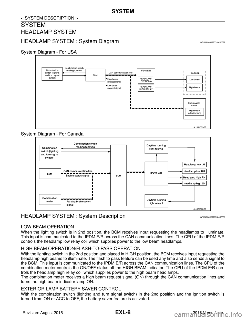
System Diagram - For USA
System Diagram - For Canada
HEADLAMP SYSTEM : System DescriptionINFOID:0000000012432770
LOW BEAM OPERATION
When the lighting switch is in 2nd position, the BCM receives input requesting the headlamps to illuminate.
This input is communicated to the IPDM E/R across the CAN communication lines. The CPU of the IPDM E/R
controls the headlamp low relay coil which supplies power to the low beam headlamps.
HIGH BEAM OPERATION/FLASH-TO-PASS OPERATION
With the lighting switch in the 2nd position and placed in HIGH position, the BCM receives input requesting the
headlamp high beams to illuminate. The flash to pass f eature can be used any time and also sends a signal to
the BCM. This input is communicated to the IPDM E/R across the CAN communication lines. The CPU of the
combination meter controls the ON/OFF status off the HIGH BEAM indicator. The CPU of the IPDM E/R con-
trols the headlamp high relay coil which supplies power to the high beam headlamps.
The combination meter receives a high beam request signal (ON) through the CAN communication lines and
turns the high beam indicator lamp ON.
EXTERIOR LAMP BATTERY SAVER CONTROL
With the combination switch (lighting and turn signal switch) in the 2nd position and the ignition switch is
turned from ON or ACC to OFF, the battery saver feature is activated.
ALLIA1579GB
ALLIA1580GB
Revision: August 2015 2016 Versa Note
cardiagn.com
Page 1661 of 3641

SYSTEMEXL-9
< SYSTEM DESCRIPTION >
C
DE
F
G H
I
J
K
M A
B
EXL
N
O P
Under this condition, the headlamps remain illuminated for 45 seconds unless the lighting switch position is
changed. If the lighting switch position is changed, then the headlamps are turned off.
This setting can be changed by CONSULT. Refer to BCS-20, "
HEADLAMP : CONSULT Function (BCM -
HEAD LAMP)" (with Intelligent Key system) or BCS-93, "HEADLAMP : CONSULT Function (BCM - HEAD
LAMP)" (without Intelligent Key system).
DAYTIME RUNNING LIGHT SYSTEM
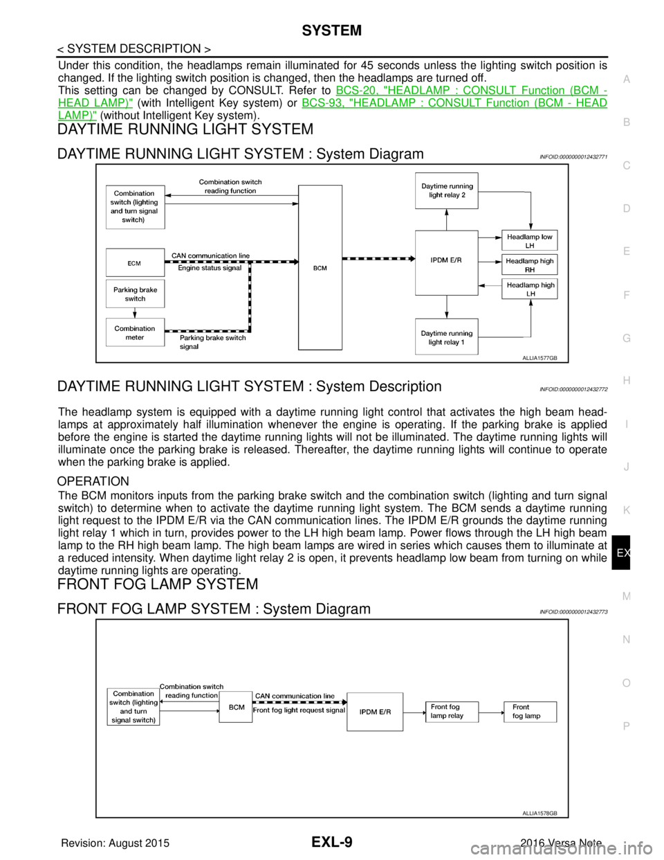
DAYTIME RUNNING LIGHT SYSTEM : System DiagramINFOID:0000000012432771
DAYTIME RUNNING LIGHT SYST EM : System DescriptionINFOID:0000000012432772
The headlamp system is equipped with a daytime running light control that activates the high beam head-
lamps at approximately half illumination whenever the e ngine is operating. If the parking brake is applied
before the engine is started the daytime running lights will not be illuminated. The daytime running lights will
illuminate once the parking brake is released. Thereaf ter, the daytime running lights will continue to operate
when the parking brake is applied.
OPERATION
The BCM monitors inputs from the parking brake swit ch and the combination switch (lighting and turn signal
switch) to determine when to activate the daytime running light system. The BCM sends a daytime running
light request to the IPDM E/R via the CAN communication lines. The IPDM E/R grounds the daytime running
light relay 1 which in turn, provides power to the LH high beam lamp. Power flows through the LH high beam
lamp to the RH high beam lamp. The high beam lamps are wired in series which causes them to illuminate at
a reduced intensity. When daytime light relay 2 is open, it prevents headlamp low beam from turning on while
daytime running lights are operating.
FRONT FOG LAMP SYSTEM
FRONT FOG LAMP SYSTEM : System DiagramINFOID:0000000012432773
ALLIA1577GB
ALLIA1578GB
Revision: August 2015 2016 Versa Note
cardiagn.com
Page 1674 of 3641

EXL-22
< SYSTEM DESCRIPTION >
DIAGNOSIS SYSTEM (IPDM E/R)
ECU IDENTIFICATION
The IPDM E/R part number is displayed.
SELF DIAGNOSTIC RESULT
Refer to PCS-20, "DTCIndex".
DATA MONITOR
ACTIVE TEST
Data Monitor The IPDM E/R input/output data is displayed in real time.
Active Test The IPDM E/R activates outputs to test components.
CAN Diag Support Mntr The result of transmit/receive diagnosis of CAN communication is displayed.
Direct Diagnostic Mode
Description
Monitor Item [Unit]Main
Signals Description
MOTOR FAN REQ [1/2/3/4] ×Indicates cooling fan speed signal received from ECM on CAN communication
line
AC COMP REQ [On/Off] ×Indicates A/C compressor request signal received from ECM on CAN commu-
nication line
TAIL&CLR REQ [On/Off] ×Indicates position light request signal received from BCM on CAN communica-
tion line
HL LO REQ [On/Off] ×Indicates low beam request signal received from BCM on CAN communication
line
HL HI REQ [On/Off] ×Indicates high beam request signal received from BCM on CAN communication
line
FR FOG REQ [On/Off] ×Indicates front fog light request signal received from BCM on CAN communica-
tion line
FR WIP REQ [Stop/1LOW/Low/Hi] ×Indicates front wiper request signal received from BCM on CAN communication
line
WIP AUTO STOP [STOP P/ACT P] ×Indicates condition of front wiper auto stop signal
WIP PROT [Off/BLOCK] ×Indicates condition of front wiper fail-safe operation
IGN RLY1 -REQ [On/Off] Indicates ignition switch ON signal received from BCM on CAN communication
line
IGN RLY [On/Off] ×Indicates condition of ignition relay
PUSH SW [On/Off] Indicates condition of push-button ignition switch
INTER/NP SW [On/Off] Indicates condition of CVT shift position
ST RLY CONT [On/Off] Indicates starter relay status signal received from BCM on CAN communication
line
IHBT RLY -REQ [On/Off] Indicates starter control relay signal received from BCM on CAN communication
line
ST/INHI RLY [Off/ ST /INHI] Indicates condition of starter relay and starter control relay
DETENT SW [On/Off] Indicates condition of CVT shift selector (park position switch)
DTRL REQ [Off] Indicates daytime running light request signal received from BCM on CAN com-
munication line
THFT HRN REQ [On/Off] Indicates theft warning horn request signal received from BCM on CAN commu-
nication line
HORN CHIRP [On/Off] Indicates horn reminder signal received from BCM on CAN communication line
Te s t i t e m D e s c r i p t i o n
HORN This test is able to check horn operation [On].
FRONT WIPER This test is able to check wiper motor operation [Hi/Lo/Off].
Revision: August 2015 2016 Versa Note
cardiagn.com
Page 1729 of 3641

HEADLAMP (HI) CIRCUITEXL-77
< DTC/CIRCUIT DIAGNOSIS >
C
DE
F
G H
I
J
K
M A
B
EXL
N
O P
HEADLAMP (HI) CIRCUIT
DescriptionINFOID:0000000012432804
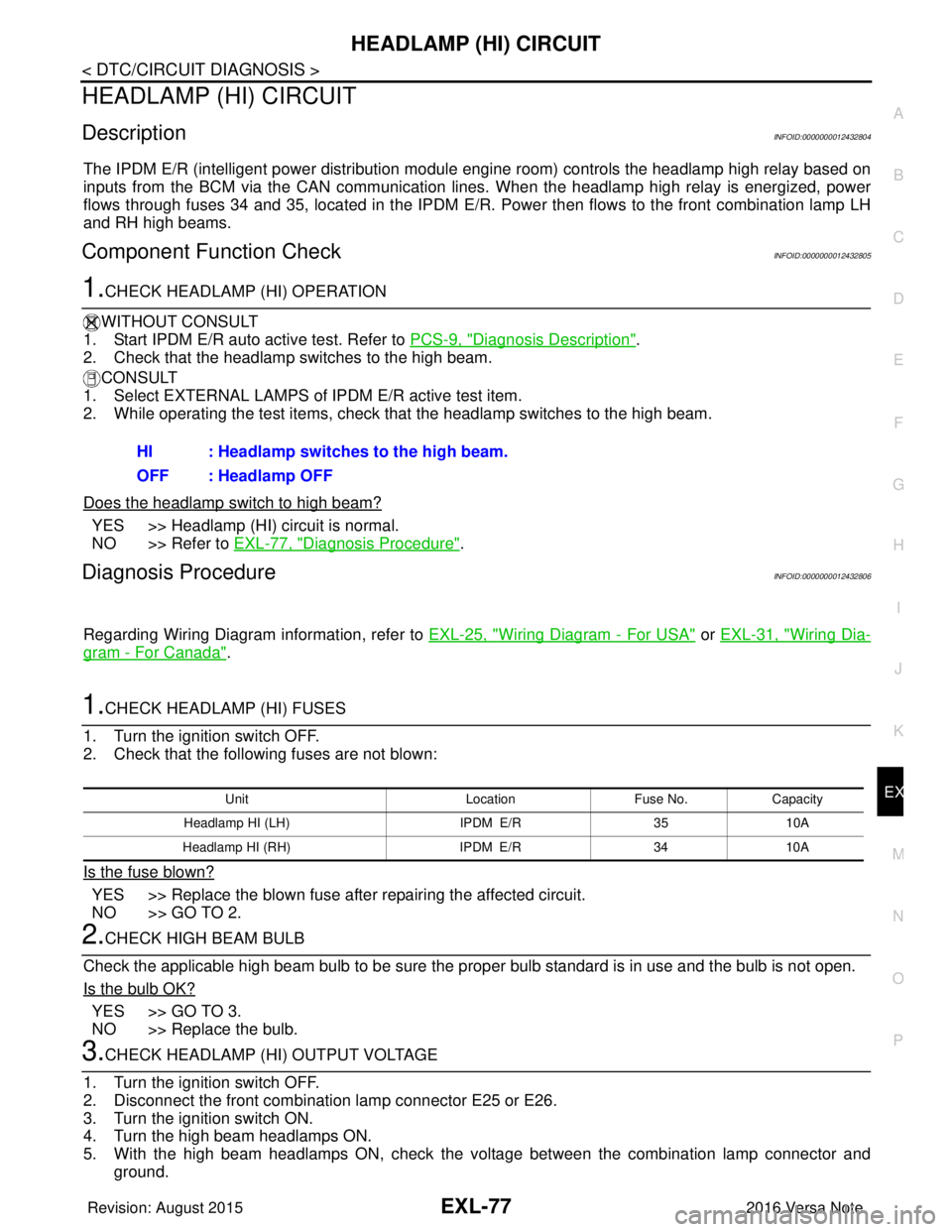
The IPDM E/R (intelligent power distribution modul e engine room) controls the headlamp high relay based on
inputs from the BCM via the CAN communication lines. When the headlamp high relay is energized, power
flows through fuses 34 and 35, located in the IPDM E/R. Power then flows to the front combination lamp LH
and RH high beams.
Component Function CheckINFOID:0000000012432805
1.CHECK HEADLAMP (HI) OPERATION
WITHOUT CONSULT
1. Start IPDM E/R auto active test. Refer to PCS-9, "
Diagnosis Description".
2. Check that the headlamp switches to the high beam.
CONSULT
1. Select EXTERNAL LAMPS of IP DM E/R active test item.
2. While operating the test items, check that the headlamp switches to the high beam.
Does the headlamp switch to high beam?
YES >> Headlamp (HI) circuit is normal.
NO >> Refer to EXL-77, "
Diagnosis Procedure".
Diagnosis ProcedureINFOID:0000000012432806
Regarding Wiring Diagram information, refer to EXL-25, "Wiring Diagram - For USA" or EXL-31, "Wiring Dia-
gram - For Canada".
1.CHECK HEADLAMP (HI) FUSES
1. Turn the ignition switch OFF.
2. Check that the following fuses are not blown:
Is the fuse blown?
YES >> Replace the blown fuse after repairing the affected circuit.
NO >> GO TO 2.
2.CHECK HIGH BEAM BULB
Check the applicable high beam bulb to be sure the proper bulb standard is in use and the bulb is not open.
Is the bulb OK?
YES >> GO TO 3.
NO >> Replace the bulb.
3.CHECK HEADLAMP (HI) OUTPUT VOLTAGE
1. Turn the ignition switch OFF.
2. Disconnect the front combination lamp connector E25 or E26.
3. Turn the ignition switch ON.
4. Turn the high beam headlamps ON.
5. With the high beam headlamps ON, check the vo ltage between the combination lamp connector and
ground. HI : Headlamp switches to the high beam.
OFF : Headlamp OFF
Unit
LocationFuse No.Capacity
Headlamp HI (LH) IPDM E/R3510A
Headlamp HI (RH) IPDM E/R3410A
Revision: August 2015 2016 Versa Note
cardiagn.com
Page 1743 of 3641

EXTERIOR LIGHTING SYSTEM SYMPTOMSEXL-91
< SYMPTOM DIAGNOSIS >
C
DE
F
G H
I
J
K
M A
B
EXL
N
O P
SYMPTOM DIAGNOSIS
EXTERIOR LIGHTING SYSTEM SYMPTOMS
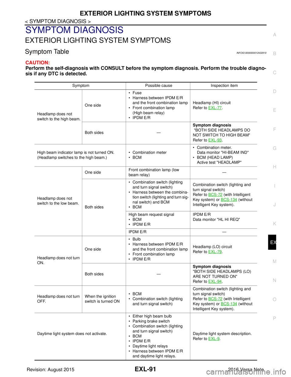
Symptom TableINFOID:0000000012432819
CAUTION:
Perform the self-diagnosis with CONSULT before th e symptom diagnosis. Perform the trouble diagno-
sis if any DTC is detected.
Symptom Possible causeInspection item
Headlamp does not
switch to the high beam. One side
•Fuse
• Harness between IPDM E/R
and the front combination lamp
• Front combination lamp
(High beam relay)
• IPDM E/R Headlamp (HI) circuit
Refer to EXL-77
.
Both sides — Symptom diagnosis
"BOTH SIDE HEADLAMPS DO
NOT SWITCH TO HIGH BEAM"
Refer to EXL-93
.
High beam indicator lamp is not turned ON.
(Headlamp switches to the high beam.) • Combination meter
•BCM• Combination meter.
Data monitor "HI-BEAM IND"
• BCM (HEAD LAMP)
Active test "HEADLAMP"
Headlamp does not
switch to the low beam. One side
Front combination lamp (low
beam relay) —
Both sides • Combination switch (lighting
and turn signal switch)
• Harness between the combina- tion switch (lighting and turn sig-
nal switch) and BCM
•BCM Combination switch (lighting and
turn signal switch)
Refer to BCS-72
(with Intelligent
Key system) or BCS-134
(without
Intelligent Key system).
High beam request signal
•BCM
• IPDM E/R IPDM E/R
Data monitor "HL HI REQ"
IPDM E/R —
Headlamp does not turn
ON. One side
•Bulb
• Harness between IPDM E/R
and the front combination lamp
• Front combination lamp
• IPDM E/R Headlamp (LO) circuit
Refer to EXL-79
.
Both sides — Symptom diagnosis
"BOTH SIDE HEADLAMPS (LO)
ARE NOT TURNED ON"
Refer to EXL-94
.
Headlamp does not turn
OFF. When the ignition
switch is turned ON•BCM
• Combination switch (lighting
and turn signal switch) Combination switch (lighting and
turn signal switch)
Refer to BCS-72
(with Intelligent
Key system) or BCS-134
(without
Intelligent Key system).
Daytime light system does not activate. • Either high beam bulb
• Parking brake switch
• Combination switch (lighting
and turn signal switch)
•BCM
• IPDM E/R
• Daytime light relays
• Harness between IPDM E/R
and daytime light relays. Daytime light system description.
Refer to EXL-9
.
Revision: August 2015
2016 Versa Note
cardiagn.com