2016 NISSAN NOTE tire type
[x] Cancel search: tire typePage 141 of 3641
![NISSAN NOTE 2016 Service Repair Manual AV-136
< SYSTEM DESCRIPTION >[NAVIGATION]
SYSTEM
• AV control unit calculates the vehicle location based
on the signals from GYRO (angle speed sensor), vehi-
cle sensor, and GPS satellite, as well NISSAN NOTE 2016 Service Repair Manual AV-136
< SYSTEM DESCRIPTION >[NAVIGATION]
SYSTEM
• AV control unit calculates the vehicle location based
on the signals from GYRO (angle speed sensor), vehi-
cle sensor, and GPS satellite, as well](/manual-img/5/57363/w960_57363-140.png)
AV-136
< SYSTEM DESCRIPTION >[NAVIGATION]
SYSTEM
• AV control unit calculates the vehicle location based
on the signals from GYRO (angle speed sensor), vehi-
cle sensor, and GPS satellite, as well as the map data from map SD-card. The vehicle location is displayed
on the AV control unit.
POSITION DETECTION PRINCIPLE
The navigation system periodically calculates the vehicle's current position according to the following three
signals:
• Travel distance of the vehicle as determined by the vehicle speed sensor
• Turning angle of the vehicle as determined by the gyroscope (angular velocity sensor)
• Direction of vehicle travel as determined by the GPS antenna (GPS information)
The current position of the vehicle is then identified by comparing the calculated vehicle position with map data
read from the map SD-card (map-matching), and indica ted on the screen as a vehicle mark. More accurate
data is judged and used by comparing vehicle position detection results found by the GPS with the result by
map-matching.
The current vehicle position will be calculated by detecting the dis-
tance the vehicle moved from the previous calculation point and its
direction.
• Travel distance Travel distance calculations are based on the vehicle speed sen-
sor input signal. Therefore, the calculation may become incorrect
as the tires wear down. To prevent this, an automatic distance cor-
rection function has been adopted.
• Travel direction
Change in the travel direction of the vehicle is calculated by a gyro-
scope (angular velocity sensor) and a GPS antenna (GPS informa-
tion). They have both advantages and disadvantages.
More accurate traveling direction is detected becaus e priorities are set for the signals from these two
devices according to the situation.
MAP-MATCHING
Map-matching compares a current location detected by the method
in the “Location Detection Princi ple” with a road map data from map
SD-card.
NOTE:
The road map data is based on data stored in the map SD-card.
The vehicle position may not be corrected under the foll owing circumstances and after driving for a certain
time when GPS information is difficult to receive. In this case, the vehicle mark on the display must be cor-
rected manually.
SEL684V
Type Advantage Disadvantage
Gyroscope
(angular velocity sensor) Can detect the vehicle's turning angle quite
accurately. Direction errors
may accumulate when vehicle is
driven for long distances without stopping.
GPS antenna
(GPS information) Can detect the vehicle's travel direction
(North/South/East/West). Correct direction cannot be detected when vehicle
speed is low.
SEL685V
Revision: August 2015
2016 Versa Note
cardiagn.com
Page 453 of 3641
![NISSAN NOTE 2016 Service Repair Manual PRECAUTIONSBRC-5
< PRECAUTION > [VDC/TCS/ABS]
C
D
E
G H
I
J
K L
M A
B
BRC
N
O P
Precaution for Brake Control SystemINFOID:0000000012430822
• Just after starting vehicle after ignition switch is ON, NISSAN NOTE 2016 Service Repair Manual PRECAUTIONSBRC-5
< PRECAUTION > [VDC/TCS/ABS]
C
D
E
G H
I
J
K L
M A
B
BRC
N
O P
Precaution for Brake Control SystemINFOID:0000000012430822
• Just after starting vehicle after ignition switch is ON,](/manual-img/5/57363/w960_57363-452.png)
PRECAUTIONSBRC-5
< PRECAUTION > [VDC/TCS/ABS]
C
D
E
G H
I
J
K L
M A
B
BRC
N
O P
Precaution for Brake Control SystemINFOID:0000000012430822
• Just after starting vehicle after ignition switch is ON, brake pedal may vibrate or motor operating noise may be heard from engine compartment. This is a normal condition.
• When an error is indicated by ABS or another warning lamp, collect all necessary information from customer
(what symptoms are present under what conditions) and check for simple causes before starting diagnostic
servicing. Besides electrical system inspection, c heck brake booster operation, brake fluid level and oil
leaks.
• If tire size and type are used in an improper combinati on or brake pads are not Genuine NISSAN parts, stop-
ping distance or steering stability may deteriorate.
• ABS might be out of order or malfunctions by putting a radio (wiring inclusive), an antenna and a lead-in wire
near the control unit.
• If aftermarket parts (car stereo, CD player, etc.) have been installed, check for incidents such as harness pinches, open circuits, and improper wiring.
• VDC system may not operate normally or a VDC OFF indi cator lamp or SLIP indicator lamp may light.
- When replacing the following parts with parts other than genuine parts or making modifications: Suspension- related parts (shock absorber, spring, bushing, etc.), tire s, wheels (other than specified sizes), brake-related
parts (pad, rotor, caliper, etc.), engine-related parts (muffler, ECM, etc.) and body reinforcement-related parts
(roll bar, tower bar, etc.).
- When driving with worn or deteriorated suspension, tires and brake-related parts.
Precaution for Harness RepairINFOID:0000000012430823
• Solder the repair part, and wrap it with tape. [Twisted wire fray
must be 110 mm (4.33 in) or less.]
• Do not bypass the repair point with wire. (If it is bypassed, the turn- out point cannot be separated and the twisted wire characteristics
are lost.)
SKIB8766E
SKIB8767E
Revision: August 2015 2016 Versa Note
cardiagn.com
Page 1847 of 3641
FSU-2
< PRECAUTION >
PRECAUTIONS
PRECAUTION
PRECAUTIONS
Precaution for Supplemental Restraint System (SRS) "AIR BAG" and "SEAT BELT
PRE-TENSIONER"
INFOID:0000000012430294
The Supplemental Restraint System such as “A IR BAG” and “SEAT BELT PRE-TENSIONER”, used along
with a front seat belt, helps to reduce the risk or severity of injury to the driver and front passenger for certain
types of collision. Information necessary to service the system safely is included in the SR and SB section of
this Service Manual.
WARNING:
• To avoid rendering the SRS inopera tive, which could increase the risk of personal injury or death in
the event of a collision which would result in air bag inflation, all maintenance must be performed by
an authorized NISSAN/INFINITI dealer.
• Improper maintenance, including in correct removal and installation of the SRS, can lead to personal
injury caused by unintent ional activation of the system. For re moval of Spiral Cable and Air Bag
Module, see the SR section.
• Do not use electrical test equipmen t on any circuit related to the SRS unless instructed to in this
Service Manual. SRS wiring harn esses can be identified by yellow and/or orange harnesses or har-
ness connectors.
PRECAUTIONS WHEN USING POWER TOOLS (AIR OR ELECTRIC) AND HAMMERS
WARNING:
• When working near the Airbag Diagnosis Sensor Unit or other Airbag System sensors with the Igni-
tion ON or engine running, DO NOT use air or electri c power tools or strike near the sensor(s) with a
hammer. Heavy vibration could activate the sensor( s) and deploy the air bag(s), possibly causing
serious injury.
• When using air or electric power tools or hammers , always switch the Ignition OFF, disconnect the
battery and wait at least three minutes before performing any service.
Precaution for Procedure without Cowl Top CoverINFOID:0000000012430295
When performing the procedure after removing cowl top cover, cover
the lower end of windshield with urethane, etc to prevent damage to
windshield.
Precaution for SuspensionINFOID:0000000012430296
• When installing rubber bushings, the final tightening mu st be carried out under unladen conditions with tires
on ground. Spilled oil might shorten the life of rubber bushings. Be sure to wipe off any spilled oil.
- Unladen conditions mean that fuel, engine coolant and lubricant are full. Spare tire, jack, hand tools and mats are in designated positions.
• After servicing suspension parts, be sure to check wheel alignment.
• Self-lock nuts are not reusable. Always use new ones when installing. Since new self-lock nuts are pre-oiled,
tighten as they are.
• When jacking up the vehicle with a floor jack, do not hang the jack on the torque rod.
PIIB3706J
Revision: August 2015 2016 Versa Note
cardiagn.com
Page 1852 of 3641
WHEEL ALIGNMENTFSU-7
< PERIODIC MAINTENANCE >
C
DF
G H
I
J
K L
M A
B
FSU
N
O P
WHEEL ALIGNMENT
InspectionINFOID:0000000012430301
PRELIMINARY INSPECTION
WARNING:
Always adjust the wheel alignment with the vehicle on a flat surface.
NOTE:
If the wheel alignment is out of s pecification, inspect and replace any damaged or worn rear suspension parts
before making any adjustments.
1. Check and adjust the wheel alignment with the vehicle under unladen conditions. “Unladen conditions”
means that the fuel, engine coolant, and lubricants are full; the spare tire, jack, hand tools and mats are in
designated positions.
2. Check the tires for incorrect air pressure and excessive wear.
3. Check the wheels for run out and damage. Refer to WT-54, "
Wheel".
4. Check the wheel bearing axial end play. Refer to FAX-27, "
Wheel Bearing".
5. Check the shock absorbers for leaks or damage.
6. Check each mount point of the suspension co mponents for any excessive looseness or damage.
7. Check each link, arm, and the suspension member for any damage.
8. Check the vehicle height. Refer to FSU-21, "
Wheelarch Height (Unladen*)".
GENERAL INFORMATION AND RECOMMENDATIONS
1. A Four-Wheel Thrust Alignment should be performed.
• This type of alignment is recomm ended for any NISSAN/INFINITI vehicle.
• The four-wheel “thrust” process helps ensure that the vehicle is properly aligned and the steering wheel
is centered.
• The alignment machine itself should be capabl e of accepting any NISSAN/INFINITI vehicle.
• The alignment machine should be checked to ensure that it is level.
2. Make sure the alignment machine is properly calibrated. • Your alignment machine should be regularly calibrated in order to give correct information.
• Check with the manufacturer of your specific a lignment machine for their recommended Service/Cali-
bration Schedule.
ALIGNMENT PROCESS
IMPORTANT: Use only the alignment specifications listed in this Service Manual. Refer to FSU-20, "Wheel
Alignment (Unladen*1)".
• When displaying the alignment settings, many alignment machines use “indicators”: (Green/red, plus or
minus, Go/No Go). Do NOT use these indicators.
- The alignment specifications programmed into your alignment machine that operate these indicators may
not be correct.
- This may result in an ERROR.
• Most camera-type alignment machines are equipped with "Rolling Compensation" method and optional
"Jacking Compensation" method to "compensate" the alignment targets or head units.
"Rolling Compensation" is the preferred method.
- If using the "Rolling Compensation" method, after inst alling the alignment targets or head units, push or pull
on the rear wheel to move the vehicle. Do not push or pull on the vehicle body.
- If using the "Jacking Compensation" method, after inst alling the alignment targets or head units, raise the
vehicle and rotate the wheels 1/2 turn in either direction.
NOTE:
Do not use the "Rolling Compensation" method if you are using sensor-type alignment equipment.
• Follow all instructions for the alignment machine you're using for more information.
CAMBER, CASTER AND KINGPIN INCLINATION ANGLES INSPECTION
• Camber, caster, kingpin inclination angles cannot be adjusted.
• Before inspection, set the front wheels onto a turning radius gauge. Set the rear wheels onto a pad that has
the same height so the vehicle will remain horizontal.
TOTAL TOE-IN INSPECTION
Measure the total toe-in using the following procedure.
Revision: August 2015 2016 Versa Note
cardiagn.com
Page 1922 of 3641
GI-34
< VEHICLE INFORMATION >
IDENTIFICATION INFORMATION
Identification Number
INFOID:0000000012433176
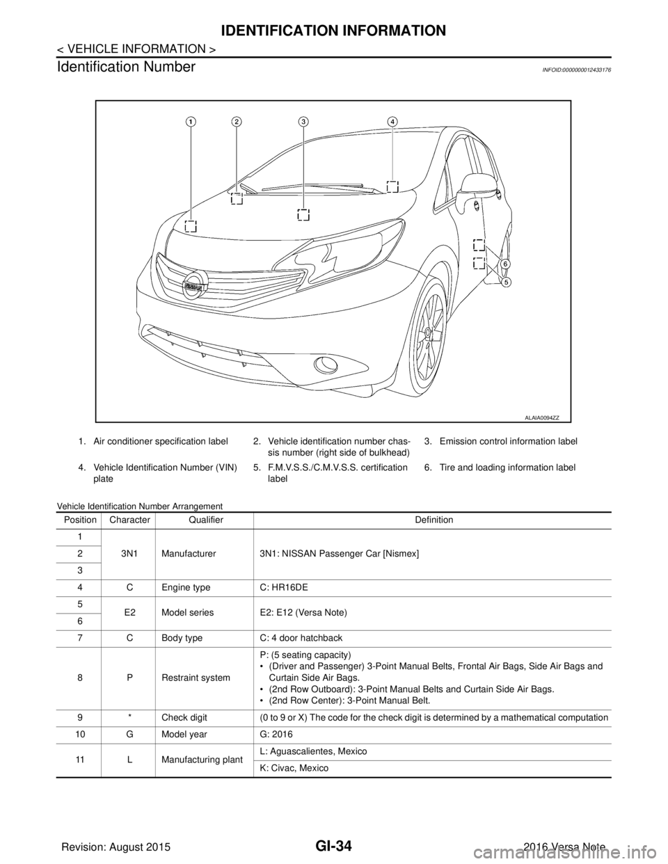
Vehicle Identification Number Arrangement
1. Air conditioner specification label 2. Vehicle identification number chas- sis number (right side of bulkhead)3. Emission control information label
4. Vehicle Identification Number (VIN) plate 5. F.M.V.S.S./C.M.V.S.S. certification
label 6. Tire and loading information label
ALAIA0094ZZ
Position Character Qualifier
Definition
1 3N1 Manufacturer 3N1: NISSAN Passenger Car [Nismex]
2
3
4 C Engine type C: HR16DE
5 E2 Model series E2: E12 (Versa Note)
6
7 C Body type C: 4 door hatchback
8 P Restraint system P: (5 seating capacity)
• (Driver and Passenger) 3-Point Manual Belts, Frontal Air Bags, Side Air Bags and
Curtain Side Air Bags.
• (2nd Row Outboard): 3-Point Manual Belts and Curtain Side Air Bags.
• (2nd Row Center): 3-Point Manual Belt.
9 * Check digit (0 to 9 or X) The code for the check digit is determined by a mathematical computation
10 G Model year G: 2016
11 L Manufacturing plant L: Aguascalientes, Mexico
K: Civac, Mexico
Revision: August 2015
2016 Versa Note
cardiagn.com
Page 2323 of 3641
MA-8
< PERIODIC MAINTENANCE >
PERIODIC MAINTENANCE
NOTE:
(1) After 40,000 miles (64,000 km) or 48 months, inspect every 10,000 miles (16,000 km) or 12 months. Replace the drive belts if found
damaged.
(2) If operating mainly in dusty conditions, more frequent maintenance may be required.
(3) Maintenance-free item. For service procedures, refer to FL section.
(4) First replacement interval is 105,000 miles (168,000 km) or 84 months. After first replacement, replace every 75,000 miles (120,000
km) or 60 months.
(5) Use only Genuine NISSAN Long Life Antifreeze / Coolant (blue) or equivalent with proper mixture ratio of 50% antifreeze and 50%
demineralized or distilled water. Mixing any other type of coolant or the use of non-distilled water will reduce the life expec tancy of the
factory-fill coolant.
(6) Replace spark plug when the spark plug gap exceeds 1.35 mm (0.053 in), even if within specified periodic replacement mileag e.
(7) Periodic maintenance is not required. However, if valve noise increases, inspect valve clearance.
*: Maintenance items and intervals with “*” are recommended by NISSAN for reli able vehicle operation. The owner need not perform
such maintenance in order to maintain the emission warranty or manufacturer recall liability. Other maintenance items and inter vals are
required.
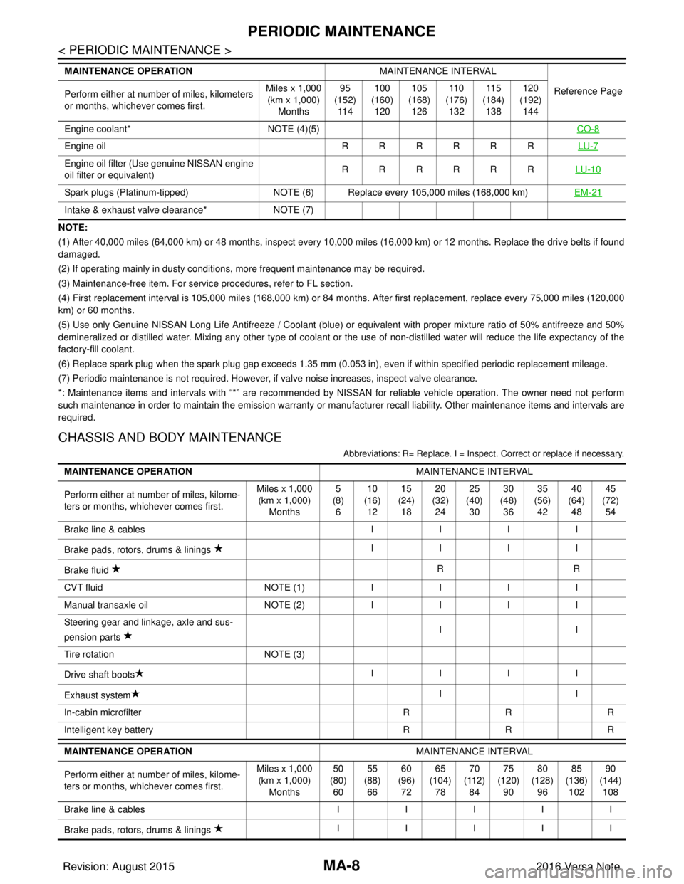
CHASSIS AND BODY MAINTENANCE
Abbreviations: R= Replace. I = Inspec t. Correct or replace if necessary.
Engine coolant* NOTE (4)(5) CO-8
Engine oil RRRRRRLU-7
Engine oil filter (Use genuine NISSAN engine
oil filter or equivalent) RRRRRR
LU-10
Spark plugs (Platinum-tipped)NOTE (6) Replace every 105,000 miles (168,000 km) EM-21
Intake & exhaust valve clearance*NOTE (7)
MAINTENANCE OPERATION
MAINTENANCE INTERVAL
Reference Page
Perform either at number of miles, kilometers
or months, whichever comes first. Miles x 1,000
(km x 1,000)
Months 95
(152)
11 4 100
(160)
120 105
(168)
126 11 0
(176)
132 11 5
(184)
138 120
(192)
144
MAINTENANCE OPERATION MAINTENANCE INTERVAL
Perform either at number of miles, kilome-
ters or months, whichever comes first. Miles x 1,000
(km x 1,000)
Months 5
(8)
6 10
(16)
12 15
(24)
18 20
(32)
24 25
(40)
30 30
(48)
36 35
(56)
42 40
(64)
48 45
(72)
54
Brake line & cables IIII
Brake pads, rotors, drums & linings IIII
Brake fluid RR
CVT fluid NOTE (1)IIII
Manual transaxle oil NOTE (2)IIII
Steering gear and linkage, axle and sus-
pension parts II
Tire rotation NOTE (3)
Drive shaft boots IIII
Exhaust system II
In-cabin microfilter RRR
Intelligent key battery RRR
MAINTENANCE OPERATION MAINTENANCE INTERVAL
Perform either at number of miles, kilome-
ters or months, whichever comes first. Miles x 1,000
(km x 1,000) Months 50
(80) 60 55
(88) 66 60
(96) 72 65
(104) 78 70
(112) 84 75
(120) 90 80
(128) 96 85
(136) 102 90
(144) 108
Brake line & cables III II
Brake pads, rotors, drums & linings IIIII
Revision: August 2015
2016 Versa Note
cardiagn.com
Page 2347 of 3641
MA-32
< PERIODIC MAINTENANCE >
CHASSIS AND BODY MAINTENANCE
GEAR OIL : Refilling
INFOID:0000000012432275
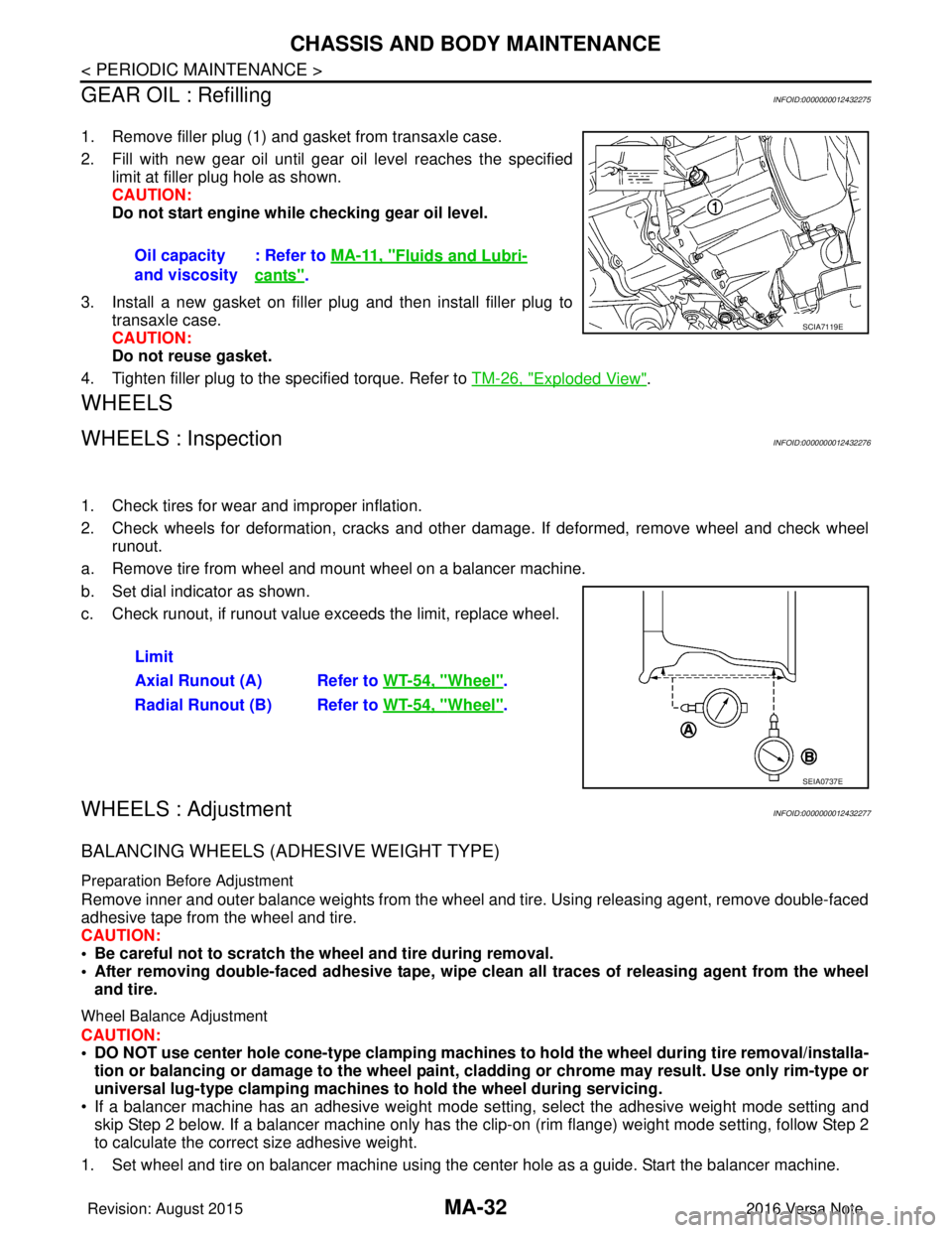
1. Remove filler plug (1) and gasket from transaxle case.
2. Fill with new gear oil until gear oil level reaches the specified limit at filler plug hole as shown.
CAUTION:
Do not start engine whil e checking gear oil level.
3. Install a new gasket on filler plug and then install filler plug to transaxle case.
CAUTION:
Do not reuse gasket.
4. Tighten filler plug to the specified torque. Refer to TM-26, "
Exploded View".
WHEELS
WHEELS : InspectionINFOID:0000000012432276
1. Check tires for wear and improper inflation.
2. Check wheels for deformation, cracks and other dam age. If deformed, remove wheel and check wheel
runout.
a. Remove tire from wheel and mount wheel on a balancer machine.
b. Set dial indicator as shown.
c. Check runout, if runout value exceeds the limit, replace wheel.
WHEELS : AdjustmentINFOID:0000000012432277
BALANCING WHEELS (ADHESIVE WEIGHT TYPE)
Preparation Before Adjustment
Remove inner and outer balance weights from the wheel and tire. Using releasing agent, remove double-faced
adhesive tape from the wheel and tire.
CAUTION:
• Be careful not to scratch the wheel and tire during removal.
• After removing double-faced adh esive tape, wipe clean all traces of releasing agent from the wheel
and tire.
Wheel Balance Adjustment
CAUTION:
• DO NOT use center hole cone-type clamping machines to hold the wheel during tire removal/installa-
tion or balancing or damage to the wheel paint, cladding or chrome may result. Use only rim-type or
universal lug-type clamping machines to hold the wheel during servicing.
• If a balancer machine has an adhesive weight mode se tting, select the adhesive weight mode setting and
skip Step 2 below. If a balancer machine only has the clip -on (rim flange) weight mode setting, follow Step 2
to calculate the correct size adhesive weight.
1. Set wheel and tire on balancer machine using the center hole as a guide. Start the balancer machine. Oil capacity
and viscosity
: Refer to
MA-11, "
Fluids and Lubri-
cants".
SCIA7119E
Limit
Axial Runout (A) Refer to WT-54, "
Wheel".
Radial Runout (B) Refer to WT-54, "
Wheel".
SEIA0737E
Revision: August 2015 2016 Versa Note
cardiagn.com
Page 2377 of 3641
![NISSAN NOTE 2016 Service Repair Manual MWI
DIAGNOSIS SYSTEM (COMBINATION METER)MWI-19
< SYSTEM DESCRIPTION > [TYPE A]
C
D
E
F
G H
I
J
K L
M B A
O P
NOTE:
Some items are not available according to vehicle specification.
WORK SUPPORT
WARNING NISSAN NOTE 2016 Service Repair Manual MWI
DIAGNOSIS SYSTEM (COMBINATION METER)MWI-19
< SYSTEM DESCRIPTION > [TYPE A]
C
D
E
F
G H
I
J
K L
M B A
O P
NOTE:
Some items are not available according to vehicle specification.
WORK SUPPORT
WARNING](/manual-img/5/57363/w960_57363-2376.png)
MWI
DIAGNOSIS SYSTEM (COMBINATION METER)MWI-19
< SYSTEM DESCRIPTION > [TYPE A]
C
D
E
F
G H
I
J
K L
M B A
O P
NOTE:
Some items are not available according to vehicle specification.
WORK SUPPORT
WARNING HISTORY
W/L ON HISTORY
• Stores histories when warning/indicator lamp is turned on.
• “W/L ON HISTORY” indicates the “TIME” when the warning/ indicator lamp is turned on.
• The “TIME” above is:
- 0: The condition that the warning/indicator lamp has been turned on 1 or more times after starting the engine and waiting for 30 seconds.
- 1 - 39: The number of times the engi ne was restarted after the 0 condition.
MIL
[ON/OFF] Displays [ON/OFF] condition of malfunction indicator.
CRUISE IND
[Off] Displays [ON/OFF]
condition of CRUISE indicator.
O/D OFF IND
[ON/OFF] Displays [ON/OFF] condition of O/D OFF indicator.
FUEL W/L
[ON/OFF] Displays [ON/OFF] condition of low-fuel warning indicator.
AIR PRES W/L
[ON/OFF] Displays [ON/OFF] condition of tire pressure warning lamp.
EPS W/L
[ON/OFF] Displays [ON/OFF] condition of EPS indicator.
CHG SIG
[On/Off] Displays [ON/OFF] condition of charge warning indicator.
PASS BUCKLE
SW
[ON/OFF] Status of seat belt buckle switch RH.
FUEL CAP W/L
[Off] Displays [ON/OFF] condition of loose fuel cap warning message.
PKB SW
[ON/OFF] Status of parking brake switch.
BUCKLE SW
[ON/OFF] Status of seat belt buckle switch LH.
BRAKE OIL SW
[ON/OFF] Status of brake fluid level switch.
DISTANCE
[M] or [Mi] Displays distance to empty.
FUEL LOW SIG
[ON/OFF] Displays [ON/OFF] condition
of low-fuel warning signal.
BUZZER
[ON/OFF] X Displays [ON/OFF] condition of buzzer.
TPMS PRESS L
[ON/OFF] Displays [ON/OFF] condition of check tire pressure warning message.
Display item [Unit]
MAIN
SIGNALS Description
Work support item
Description
Fuel meter diagnosis(Analog pointer) A possible malfunction can be narrowed down by following the displayed instructions.
Warning lamp diagnosis
Display item Description
W/L ON HISTORY Lighting history of warning lamp and indicator lamp can be checked.
Revision: August 2015 2016 Versa Note
cardiagn.com