Page 655 of 3641
DEF-4
< SYSTEM DESCRIPTION >
COMPONENT PARTS
SYSTEM DESCRIPTION
COMPONENT PARTS
Component Parts LocationINFOID:0000000012431752
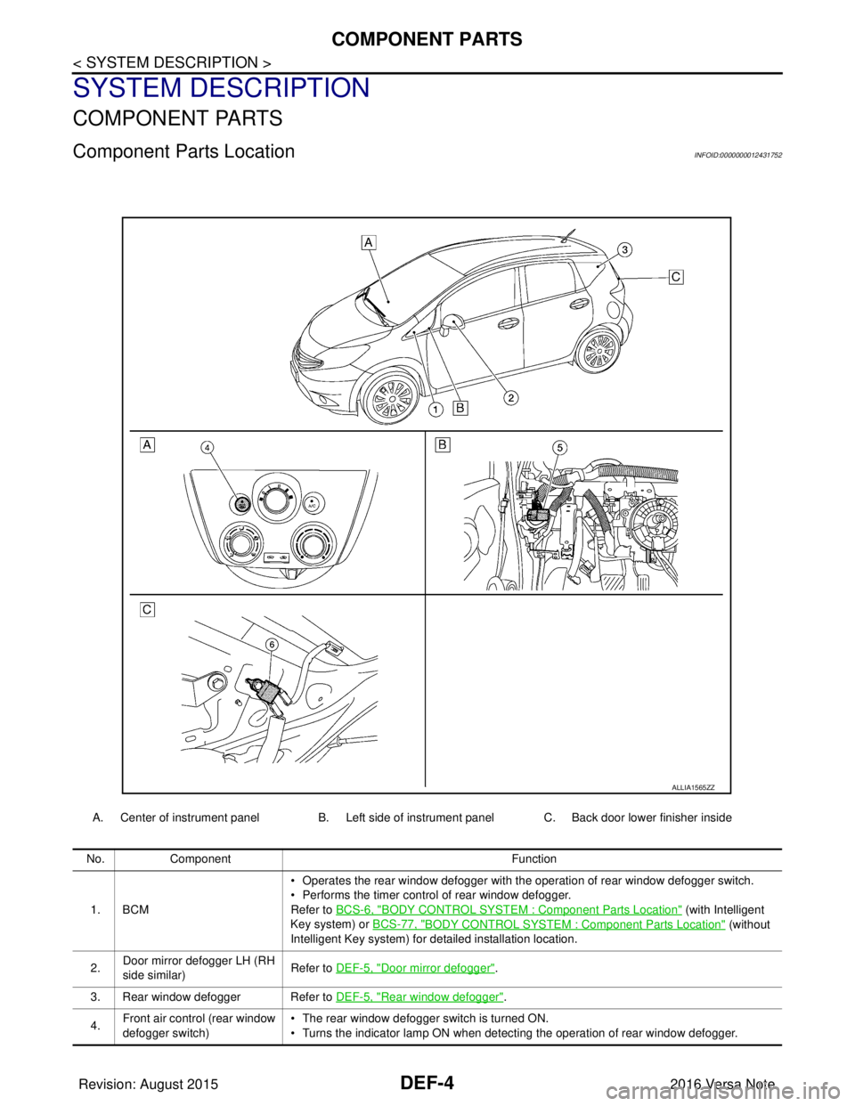
A. Center of instrument panel B. Left side of instrument panel C. Back door lower finisher inside
ALLIA1565ZZ
No.Component Function
1. BCM • Operates the rear window defogger with the operation of rear window defogger switch.
• Performs the timer control of rear window defogger.
Refer to BCS-6, "
BODY CONTROL SYSTEM : Co
mponent Parts Location" (with Intelligent
Key system) or BCS-77, "
BODY CONTROL SYSTEM : Co mponent Parts Location" (without
Intelligent Key system) for detailed installation location.
2. Door mirror defogger LH (RH
side similar)
Refer to DEF-5, "
Door mirror defogger".
3. Rear window defogger Refer to DEF-5, "
Rear window defogger".
4. Front air control (rear window
defogger switch) • The rear window defogger switch is turned ON.
• Turns the indicator lamp ON when detecting the operation of rear window defogger.
Revision: August 2015
2016 Versa Note
cardiagn.com
Page 656 of 3641
COMPONENT PARTSDEF-5
< SYSTEM DESCRIPTION >
C
DE
F
G H
I
J
K
M A
B
DEF
N
O P
Rear window defoggerINFOID:0000000012431753
Heats the heating wire with the pow er supply from the rear window
defogger relay to prevent the rear window from fogging up.
Door mirror defoggerINFOID:0000000012431754
Heats the heating wire with the pow er supply from the rear window
defogger relay to prevent the door mirror from fogging up.
5. Rear window defogger relay Operates the rear window defogger with the control signal from BCM.
6. Condenser Removes the noise that is generated when the rear window defogger turns ON/OFF.
No.
Component Function
JMLIA2595GB
JMLIA2596GB
Revision: August 2015 2016 Versa Note
cardiagn.com
Page 657 of 3641
DEF-6
< SYSTEM DESCRIPTION >
SYSTEM
SYSTEM
System DescriptionINFOID:0000000012431755
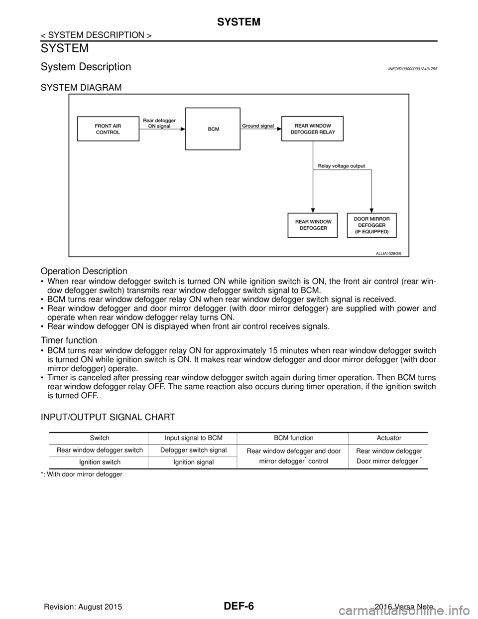
SYSTEM DIAGRAM
Operation Description
• When rear window defogger switch is turned ON while ignition switch is ON, the front air control (rear win-dow defogger switch) transmits rear window defogger switch signal to BCM.
• BCM turns rear window defogger relay ON when rear window defogger switch signal is received.
• Rear window defogger and door mirror defogger (with door mirror defogger) are supplied with power and operate when rear window defogger relay turns ON.
• Rear window defogger ON is displayed when front air control receives signals.
Timer function
• BCM turns rear window defogger relay ON for appr oximately 15 minutes when rear window defogger switch
is turned ON while ignition switch is ON. It makes rear window defogger and door mirror defogger (with door
mirror defogger) operate.
• Timer is canceled after pressing rear window defogger switch again during timer operation. Then BCM turns rear window defogger relay OFF. The same reaction also occurs during timer operation, if the ignition switch
is turned OFF.
INPUT/OUTPUT SIGNAL CHART
*: With door mirror defogger
ALLIA1028GB
Switch Input signal to BCM BCM functionActuator
Rear window defogger switch Defogger switch signal Rear window defogger and door
mirror defogger
* control Rear window defogger
Door mirror defogger *Ignition switch Ignition signal
Revision: August 2015 2016 Versa Note
cardiagn.com
Page 677 of 3641
DEF-26
< DTC/CIRCUIT DIAGNOSIS >
DRIVER SIDE DOOR MIRROR DEFOGGER
DRIVER SIDE DOOR MIRROR DEFOGGER
DescriptionINFOID:0000000012431775
Heats the heating wire with the power supply from the rear window defogger relay to prevent the door mirror
from fogging up.
Component Function CheckINFOID:0000000012431776
1. CHECK DOOR MIRROR DEFOGGER LH
Check that heating wire of door mirror defogger LH is heated when turning the rear window defogger switch
ON.
Is the inspection result normal?
YES >> Door mirror defogger is OK.
NO >> Refer to DEF-26, "
Diagnosis Procedure".
Diagnosis ProcedureINFOID:0000000012431777
Regarding Wiring Diagram information, refer to DEF-12, "Wiring Diagram".
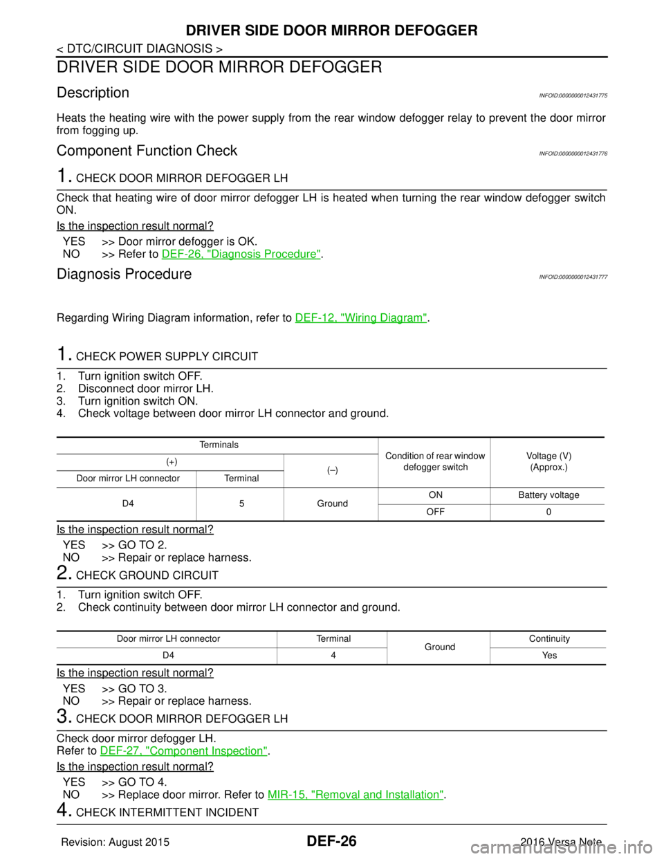
1. CHECK POWER SUPPLY CIRCUIT
1. Turn ignition switch OFF.
2. Disconnect door mirror LH.
3. Turn ignition switch ON.
4. Check voltage between door mirror LH connector and ground.
Is the inspection result normal?
YES >> GO TO 2.
NO >> Repair or replace harness.
2. CHECK GROUND CIRCUIT
1. Turn ignition switch OFF.
2. Check continuity between door mirror LH connector and ground.
Is the inspection result normal?
YES >> GO TO 3.
NO >> Repair or replace harness.
3. CHECK DOOR MIRROR DEFOGGER LH
Check door mirror defogger LH.
Refer to DEF-27, "
Component Inspection".
Is the inspection result normal?
YES >> GO TO 4.
NO >> Replace door mirror. Refer to MIR-15, "
Removal and Installation".
4. CHECK INTERMITTENT INCIDENT
Te r m i n a l s
Condition of rear window
defogger switch Voltage (V)
(Approx.)
(+)
(–)
Door mirror LH connector Terminal
D4 5Ground ON
Battery voltage
OFF 0
Door mirror LH connector Terminal
GroundContinuity
D4 4 Yes
Revision: August 2015 2016 Versa Note
cardiagn.com
Page 678 of 3641
DRIVER SIDE DOOR MIRROR DEFOGGER
DEF-27
< DTC/CIRCUIT DIAGNOSIS >
C
D E
F
G H
I
J
K
M A
B
DEF
N
O P
Check intermittent incident.
Refer to GI-42, "
Intermittent Incident".
Is the inspection result normal?
YES >> Check the following. • Battery power supply circuit.
• Fuse block (J/B).
NO >> Repair or replace the malfunctioning parts.
Component InspectionINFOID:0000000012431778
1. CHECK DOOR MIRROR DEFOGGER LH
1. Turn ignition switch OFF.
2. Disconnect door mirror LH.
3. Check continuity between door mirror terminals.
Is the inspection result normal?
YES >> Inspection End.
NO >> Replace door mirror LH. Refer to MIR-17, "
Removal and Installation".
Terminal Continuity
45 Y es
Revision: August 2015 2016 Versa Note
cardiagn.com
Page 679 of 3641
DEF-28
< DTC/CIRCUIT DIAGNOSIS >
PASSENGER SIDE DOOR MIRROR DEFOGGER
PASSENGER SIDE DOOR MIRROR DEFOGGER
DescriptionINFOID:0000000012431779
Heats the heating wire with the power supply from the rear window defogger relay to prevent the door mirror
from fogging up.
Component Function CheckINFOID:0000000012431780
1.CHECK DOOR MIRROR DEFOGGER RH
Check that the heating wire of door mirror defogger RH is heated when turning the rear window defogger
switch ON.
Is the inspection result normal?
YES >> Door mirror defogger RH is OK.
NO >> Refer to DEF-28, "
Diagnosis Procedure".
Diagnosis ProcedureINFOID:0000000012431781
Regarding Wiring Diagram information, refer to DEF-12, "Wiring Diagram".
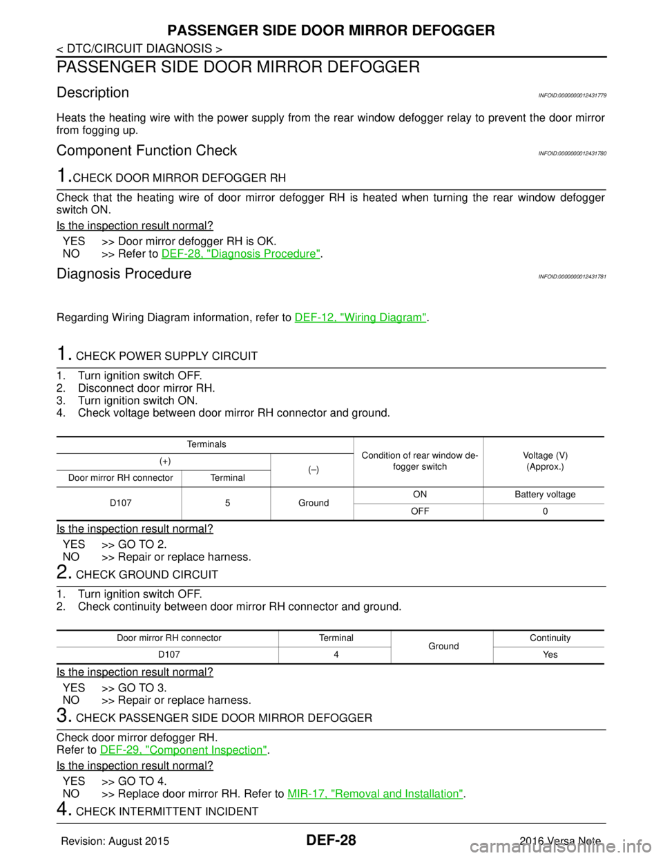
1. CHECK POWER SUPPLY CIRCUIT
1. Turn ignition switch OFF.
2. Disconnect door mirror RH.
3. Turn ignition switch ON.
4. Check voltage between door mirror RH connector and ground.
Is the inspection result normal?
YES >> GO TO 2.
NO >> Repair or replace harness.
2. CHECK GROUND CIRCUIT
1. Turn ignition switch OFF.
2. Check continuity between door mirror RH connector and ground.
Is the inspection result normal?
YES >> GO TO 3.
NO >> Repair or replace harness.
3. CHECK PASSENGER SIDE DOOR MIRROR DEFOGGER
Check door mirror defogger RH.
Refer to DEF-29, "
Component Inspection".
Is the inspection result normal?
YES >> GO TO 4.
NO >> Replace door mirror RH. Refer to MIR-17, "
Removal and Installation".
4. CHECK INTERMITTENT INCIDENT
Te r m i n a l s
Condition of rear window de-
fogger switch Voltage (V)
(Approx.)
(+)
(–)
Door mirror RH connector Terminal
D107 5Ground ON
Battery voltage
OFF 0
Door mirror RH connector Terminal
GroundContinuity
D107 4 Yes
Revision: August 2015 2016 Versa Note
cardiagn.com
Page 680 of 3641
PASSENGER SIDE DOOR MIRROR DEFOGGERDEF-29
< DTC/CIRCUIT DIAGNOSIS >
C
DE
F
G H
I
J
K
M A
B
DEF
N
O P
Check intermittent incident.
Refer to GI-42, "
Intermittent Incident".
Is the inspection result normal?
YES >> Check the following. • Battery power supply circuit.
• Fuse block (J/B).
NO >> Repair or replace the malfunctioning parts.
Component InspectionINFOID:0000000012431782
1. CHECK DOOR MIRROR DEFOGGER RH
1. Turn ignition switch OFF.
2. Disconnect door mirror RH.
3. Check continuity between door mirror terminals.
Is the inspection result normal?
YES >> Inspection End.
NO >> Replace door mirror RH. Refer to MIR-17, "
Removal and Installation".
Terminal Continuity
45 Y es
Revision: August 2015 2016 Versa Note
cardiagn.com
Page 681 of 3641
DEF-30
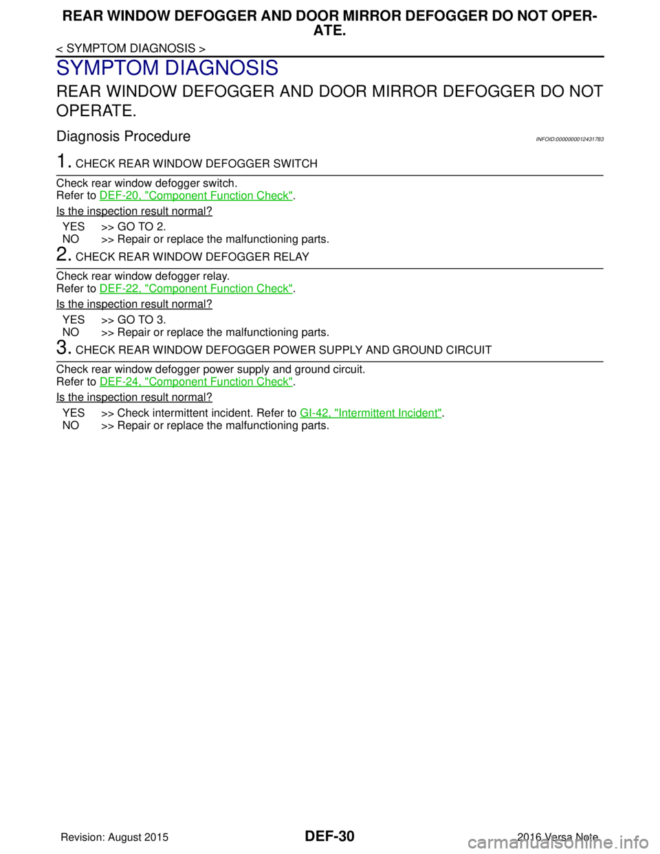
< SYMPTOM DIAGNOSIS >
REAR WINDOW DEFOGGER AND DOOR MIRROR DEFOGGER DO NOT OPER-
ATE.
SYMPTOM DIAGNOSIS
REAR WINDOW DEFOGGER AND DOOR MIRROR DEFOGGER DO NOT
OPERATE.
Diagnosis ProcedureINFOID:0000000012431783
1. CHECK REAR WINDOW DEFOGGER SWITCH
Check rear window defogger switch.
Refer to DEF-20, "
Component Function Check".
Is the inspection result normal?
YES >> GO TO 2.
NO >> Repair or replace the malfunctioning parts.
2. CHECK REAR WINDOW DEFOGGER RELAY
Check rear window defogger relay.
Refer to DEF-22, "
Component Function Check".
Is the inspection result normal?
YES >> GO TO 3.
NO >> Repair or replace the malfunctioning parts.
3. CHECK REAR WINDOW DEFOGGER POWER SUPPLY AND GROUND CIRCUIT
Check rear window defogger power supply and ground circuit.
Refer to DEF-24, "
Component Function Check".
Is the inspection result normal?
YES >> Check intermittent incident. Refer to GI-42, "Intermittent Incident".
NO >> Repair or replace the malfunctioning parts.
Revision: August 2015 2016 Versa Note
cardiagn.com