Page 2501 of 3641

PB-8
< REMOVAL AND INSTALLATION >
PARKING BRAKE REAR CABLE
PARKING BRAKE REAR CABLE
Removal and InstallationINFOID:0000000012430692
REMOVAL
1. Remove the center console assembly. Refer to IP-18, "Removal and Installation".
2. Loosen the adjusting nut. Refer to PB-6, "
Exploded View".
NOTE:
It is not necessary to remove the parking brake front cable.
3. Separate the parking brake rear cables (RH/LH ) from the parking brake front cable. Refer to PB-6,
"Exploded View".
4. Remove the rear wheels and tires using power tool. Refer to WT-48, "
Exploded View".
5. Remove rear wheel sensors. Refer to BRC-143, "
REAR SENSOR ROTOR : Removal and Installation".
6. Remove the rear drum brake components. Refer to BR-41, "
Removal and Installation".
CAUTION:
Do not separate the brake tube from the wheel cylinders.
7. Remove the center muffler. Refer to EX-5, "
Exploded View".
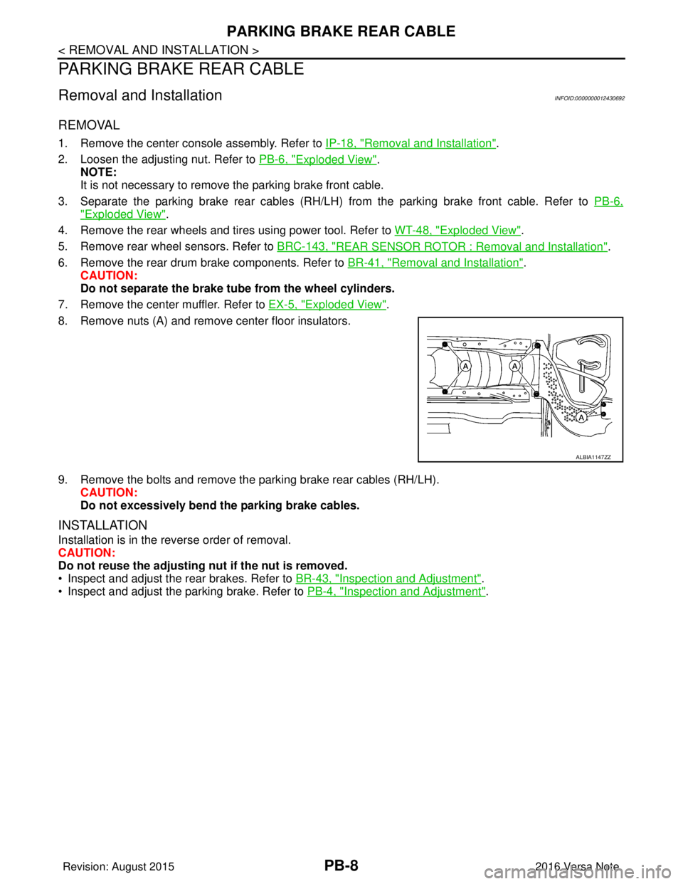
8. Remove nuts (A) and remove center floor insulators.
9. Remove the bolts and remove the parking brake rear cables (RH/LH). CAUTION:
Do not excessively bend the parking brake cables.
INSTALLATION
Installation is in the reverse order of removal.
CAUTION:
Do not reuse the adjusting nut if the nut is removed.
• Inspect and adjust the rear brakes. Refer to BR-43, "
Inspection and Adjustment".
• Inspect and adjust the parking brake. Refer to PB-4, "
Inspection and Adjustment".
ALBIA1147ZZ
Revision: August 2015 2016 Versa Note
cardiagn.com
Page 2741 of 3641

REAR SUSPENSION BEAMRSU-13
< REMOVAL AND INSTALLATION >
C
DF
G H
I
J
K L
M A
B
RSU
N
O P
REAR SUSPENSION BEAM
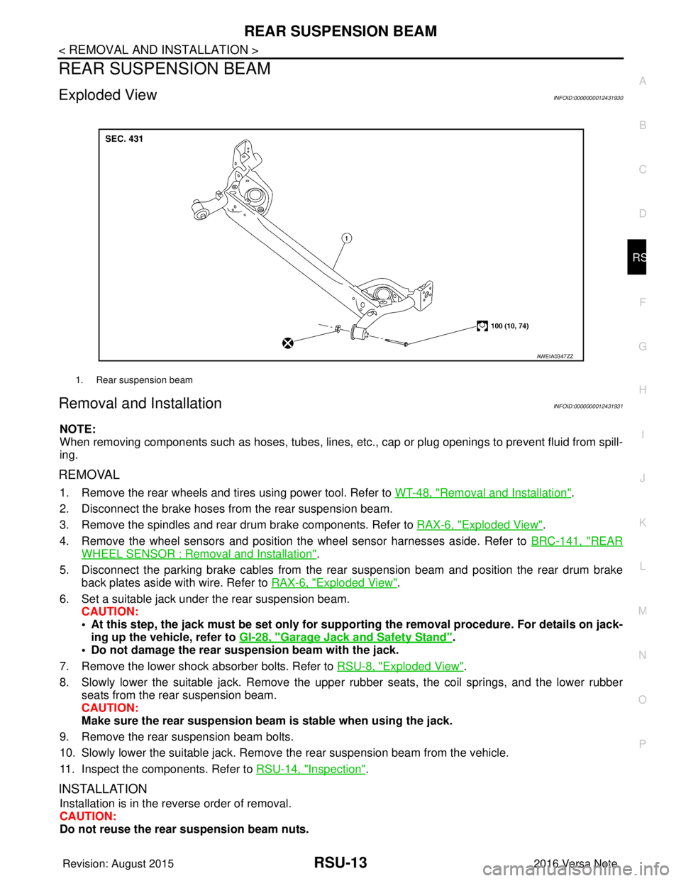
Exploded ViewINFOID:0000000012431930
Removal and InstallationINFOID:0000000012431931
NOTE:
When removing components such as hoses, tubes, lines, etc. , cap or plug openings to prevent fluid from spill-
ing.
REMOVAL
1. Remove the rear wheels and tires using power tool. Refer to WT-48, "Removal and Installation".
2. Disconnect the brake hoses from the rear suspension beam.
3. Remove the spindles and rear drum brake components. Refer to RAX-6, "
Exploded View".
4. Remove the wheel sensors and position the wheel sensor harnesses aside. Refer to BRC-141, "
REAR
WHEEL SENSOR : Removal and Installation".
5. Disconnect the parking brake cables from the rear suspension beam and position the rear drum brake
back plates aside with wire. Refer to RAX-6, "
Exploded View".
6. Set a suitable jack under the rear suspension beam. CAUTION:
• At this step, the jack must be set only for suppo rting the removal procedure. For details on jack-
ing up the vehicle, refer to GI-28, "
Garage Jack and Safety Stand".
• Do not damage the rear su spension beam with the jack.
7. Remove the lower shock absorber bolts. Refer to RSU-8, "
Exploded View".
8. Slowly lower the suitable jack. Remove the upper rubber seats, the coil springs, and the lower rubber seats from the rear suspension beam.
CAUTION:
Make sure the rear susp ension beam is stable when using the jack.
9. Remove the rear suspension beam bolts.
10. Slowly lower the suitable jack. Remove the rear suspension beam from the vehicle.
11. Inspect the components. Refer to RSU-14, "
Inspection".
INSTALLATION
Installation is in the reverse order of removal.
CAUTION:
Do not reuse the rear suspension beam nuts.
1. Rear suspension beam
AWEIA0347ZZ
Revision: August 2015 2016 Versa Note
cardiagn.com
Page 2766 of 3641

ID REGISTRATION PROCEDUREWT-23
< BASIC INSPECTION >
C
DF
G H
I
J
K L
M A
B
WT
N
O P
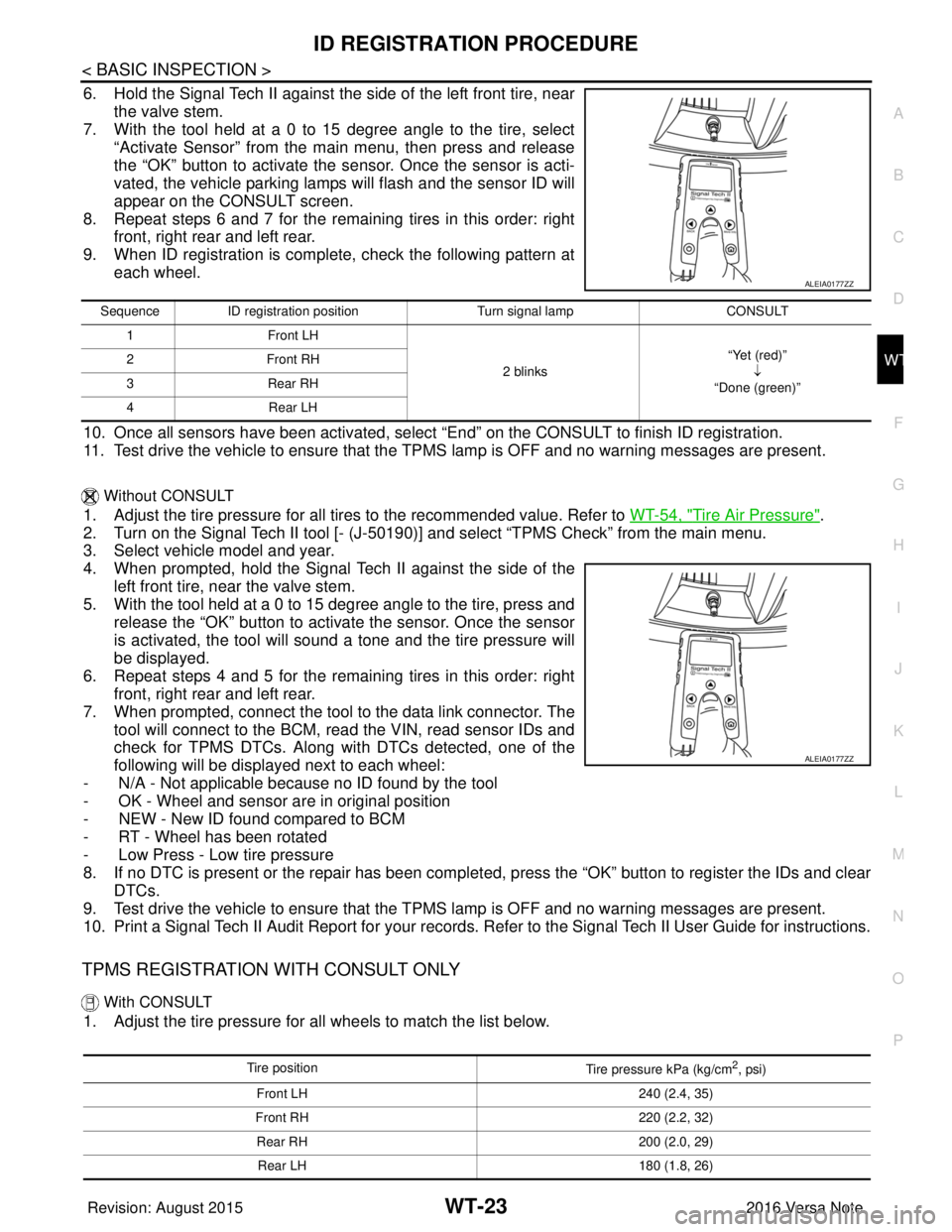
6. Hold the Signal Tech II against the side of the left front tire, near the valve stem.
7. With the tool held at a 0 to 15 degree angle to the tire, select
“Activate Sensor” from the main menu, then press and release
the “OK” button to activate the s ensor. Once the sensor is acti-
vated, the vehicle parking lamps will flash and the sensor ID will
appear on the CONSULT screen.
8. Repeat steps 6 and 7 for the remaining tires in this order: right front, right rear and left rear.
9. When ID registration is complete, check the following pattern at each wheel.
10. Once all sensors have been activated, select “End” on the CONSULT to finish ID registration.
11. Test drive the vehicle to ensure that the TPMS lamp is OFF and no warning messages are present.
Without CONSULT
1. Adjust the tire pressure for all tires to the recommended value. Refer to WT-54, "Tire Air Pressure".
2. Turn on the Signal Tech II tool [- (J-50190) ] and select “TPMS Check” from the main menu.
3. Select vehicle model and year.
4. When prompted, hold the Signal Te ch II against the side of the
left front tire, near the valve stem.
5. With the tool held at a 0 to 15 degree angle to the tire, press and release the “OK” button to activate the sensor. Once the sensor
is activated, the tool will sound a tone and the tire pressure will
be displayed.
6. Repeat steps 4 and 5 for the remaining tires in this order: right front, right rear and left rear.
7. When prompted, connect the tool to the data link connector. The tool will connect to the BCM, read the VIN, read sensor IDs and
check for TPMS DTCs. Along wit h DTCs detected, one of the
following will be displayed next to each wheel:
- N/A - Not applicable because no ID found by the tool
- OK - Wheel and sensor ar e in original position
- NEW - New ID found compared to BCM
- RT - Wheel has been rotated
- Low Press - Low tire pressure
8. If no DTC is present or the repair has been complet ed, press the “OK” button to register the IDs and clear
DTCs.
9. Test drive the vehicle to ensure that the TPMS lamp is OFF and no warning messages are present.
10. Print a Signal Tech II Audit Report for your records. Refer to the Signal Tech II User Guide for instructions.
TPMS REGISTRATION WITH CONSULT ONLY
With CONSULT
1. Adjust the tire pressure for all wheels to match the list below.
ALEIA0177ZZ
Sequence ID registration position Turn signal lamp CONSULT
1 Front LH
2 blinks“Yet (red)”
↓
“Done (green)”
2F
ro nt R H
3 Rear RH
4 Rear LH
ALEIA0177ZZ
Tire position
Tire pressure kPa (kg/cm2, psi)
Front LH 240 (2.4, 35)
Front RH 220 (2.2, 32)
Rear RH 200 (2.0, 29)
Rear LH 180 (1.8, 26)
Revision: August 2015 2016 Versa Note
cardiagn.com