2016 NISSAN NOTE front washer motor
[x] Cancel search: front washer motorPage 282 of 3641
![NISSAN NOTE 2016 Service Repair Manual BCS
DIAGNOSIS SYSTEM (BCM)BCS-21
< SYSTEM DESCRIPTION > [WITH INTELLIGENT KEY SYSTEM]
C
D
E
F
G H
I
J
K L
B A
O P
N
WORK SUPPORT
*: Initial setting
WIPER
WIPER : CONSULT Func
tion (BCM - WIPER)INFOID: NISSAN NOTE 2016 Service Repair Manual BCS
DIAGNOSIS SYSTEM (BCM)BCS-21
< SYSTEM DESCRIPTION > [WITH INTELLIGENT KEY SYSTEM]
C
D
E
F
G H
I
J
K L
B A
O P
N
WORK SUPPORT
*: Initial setting
WIPER
WIPER : CONSULT Func
tion (BCM - WIPER)INFOID:](/manual-img/5/57363/w960_57363-281.png)
BCS
DIAGNOSIS SYSTEM (BCM)BCS-21
< SYSTEM DESCRIPTION > [WITH INTELLIGENT KEY SYSTEM]
C
D
E
F
G H
I
J
K L
B A
O P
N
WORK SUPPORT
*: Initial setting
WIPER
WIPER : CONSULT Func
tion (BCM - WIPER)INFOID:0000000012432319
DATA MONITOR
ACTIVE TEST
WORK SUPPORT
ILL DIM SIGNAL This test is able to check head lamp illumination dimming operation [On/Off].
TAIL LAMP This test is able to check tail lamp operation [On/Off].
Test Item
Description
Support ItemSetting Description
BATTERY SAVER SET On*
Exterior lamp battery saver function ON.
Off Exterior lamp battery saver function OFF.
ILL DELAY SET MODE 8 180 sec.
Sets delay timer function operation time
(All doors closed).
MODE 7 150 sec.
MODE 6 120 sec.
MODE 4 60 sec.
MODE 5 90 sec.
MODE 3 30 sec.
MODE 2 OFF
MODE 1* 45 sec.
Monitor Item [Unit]
Description
PUSH SW [On/Off] Indicates condition of push-button ignition switch.
VEH SPEED 1 [km/h] Indicates vehicle speed signal received from ABS on CAN communication line.
FR WIPER HI [On/Off]
Indicates condition of wiper operation of combination switch.
FR WIPER LOW [On/Off]
FR WASHER SW [On/Off]
FR WIPER INT [On/Off]
FR WIPER STOP [On/Off]
Indicates front wiper auto stop signal received from IPDM E/R on CAN communication
line.
INT VOLUME [1 − 7] Indicates condition of intermittent wiper operation of combination switch.
RR WIPER ON [On/Off] Indicates condition of rear wiper operation of combination switch.
RR WIPER INT [On/Off]
RR WASHER SW [On/Off]
RR WIPER STOP [On/Off] Indicates rear wiper motor auto stop input from rear wiper motor.
Test Item Description
FR WIPER This test is able to check front wiper operation [INT/Lo/Hi/Off].
RR WIPER This test is able to check rear wiper operation [On/Off].
Support ItemSetting Description
WIPER SPEED SETTING On Front wiper intermittent time linked with vehicle speed and wiper dial position.
Off* Front wiper intermittent time linked with wiper dial position.
Revision: August 2015
2016 Versa Note
cardiagn.com
Page 292 of 3641
![NISSAN NOTE 2016 Service Repair Manual BCS
BCM
BCS-31
< ECU DIAGNOSIS INFORMATION > [WITH INTELLIGENT KEY SYSTEM]
C
D
E
F
G H
I
J
K L
B A
O P
N
DETE/CANCL SW
When selector lever is in P position Off
When selector lever is in any position o NISSAN NOTE 2016 Service Repair Manual BCS
BCM
BCS-31
< ECU DIAGNOSIS INFORMATION > [WITH INTELLIGENT KEY SYSTEM]
C
D
E
F
G H
I
J
K L
B A
O P
N
DETE/CANCL SW
When selector lever is in P position Off
When selector lever is in any position o](/manual-img/5/57363/w960_57363-291.png)
BCS
BCM
BCS-31
< ECU DIAGNOSIS INFORMATION > [WITH INTELLIGENT KEY SYSTEM]
C
D
E
F
G H
I
J
K L
B A
O P
N
DETE/CANCL SW
When selector lever is in P position Off
When selector lever is in any position other than P
On
DOOR STAT-AS Passenger door LOCK status
LOCK
Passenger door UNLOCK status UNLK
Wait with selective UNLOCK operation (5 seconds) READY
DOOR STAT-DR Driver door LOCK status
LOCK
Driver door UNLOCK status UNLK
Wait with selective UNLOCK operation (5 seconds) READY
DOOR SW-AS Front door RH closed
Off
Front door RH opened On
DOOR SW-BK Back door closed
Off
Back door opened On
DOOR SW-DR Front door LH closed
Off
Front door LH opened On
DOOR SW-RL Rear door LH closed
Off
Rear door LH opened On
DOOR SW-RR Rear door RH closed
Off
Rear door RH opened On
ENGINE STATE Engine stopped
Stop
While the engine stalls Stall
At engine cranking Crank
Engine running Run
FAN O N SIG Blower motor fan switch OFF
Off
Blower motor fan switch ON On
FR FOG SW Front fog lamp switch OFF
Off
Front fog lamp switch ON On
FR WASHER SW Front washer switch OFF
Off
Front washer switch ON On
FR WIPER LOW Front wiper switch OFF
Off
Front wiper switch LO On
FR WIPER HI Front wiper switch OFF
Off
Front wiper switch HI On
FR WIPER INT Front wiper switch OFF
Off
Front wiper switch INT On
FR WIPER STOP Any position other than front wiper stop position
Off
Front wiper stop position On
HAZARD SW When hazard switch is not pressed
Off
When hazard switch is pressed On
HEAD LAMP SW 1 Headlamp switch OFF
Off
Headlamp switch 1st On
HEAD LAMP SW 2 Headlamp switch OFF
Off
Headlamp switch 1st On
HI BEAM SW High beam switch OFF
Off
High beam switch HI On
Monitor Item
Condition Value/Status
Revision: August 2015 2016 Versa Note
cardiagn.com
Page 356 of 3641
![NISSAN NOTE 2016 Service Repair Manual BCS
DIAGNOSIS SYSTEM (BCM)BCS-95
< SYSTEM DESCRIPTION > [WITHOUT INTELLIGENT KEY SYSTEM]
C
D
E
F
G H
I
J
K L
B A
O P
N
ACTIVE TEST
WORK SUPPORT
* : Initial setting
FLASHER
FLASHER : CONSULT Func
tion NISSAN NOTE 2016 Service Repair Manual BCS
DIAGNOSIS SYSTEM (BCM)BCS-95
< SYSTEM DESCRIPTION > [WITHOUT INTELLIGENT KEY SYSTEM]
C
D
E
F
G H
I
J
K L
B A
O P
N
ACTIVE TEST
WORK SUPPORT
* : Initial setting
FLASHER
FLASHER : CONSULT Func
tion](/manual-img/5/57363/w960_57363-355.png)
BCS
DIAGNOSIS SYSTEM (BCM)BCS-95
< SYSTEM DESCRIPTION > [WITHOUT INTELLIGENT KEY SYSTEM]
C
D
E
F
G H
I
J
K L
B A
O P
N
ACTIVE TEST
WORK SUPPORT
* : Initial setting
FLASHER
FLASHER : CONSULT Func
tion (BCM - FLASHER)INFOID:0000000012432378
DATA MONITOR
ACTIVE TEST
AIR CONDITIONER
AIR CONDITIONER : CONSULT Func tion (BCM - AIR CONDITIONER)INFOID:0000000012432379
DATA MONITOR
FR WIPER HI [On/Off]
Indicates condition of wiper operation of combination switch.
FR WIPER LOW [On/Off]
FR WIPER INT [On/Off]
FR WASHER SW [On/Off]
FR WIPER STOP [On/Off]
Indicates front wiper auto stop signal received from IPDM E/R on CAN communication
line.
INT VOLUME [1 − 7] Indicates condition of intermittent wiper operation of combination switch.
RR WIPER ON [On/Off] Indicates condition of rear wiper operation of combination switch.
RR WIPER INT [On/Off]
RR WASHER SW [On/Off]
RR WIPER STOP [On/Off] Indicates rear wiper motor auto stop input from rear wiper motor.
REVERSE SW CAN [On/Off] Indicates reverse switch sign al received from TCM on CAN communication line.
VEHICLE SPEED [km/h/mph] Indicates vehicle speed signal received from combination meter on CAN communication
line.
Monitor Item [Unit]
Description
Test ItemDescription
FR WIPER This test is able to check front wiper operation [INT/Lo/Hi/Off].
RR WIPER This test is able to check rear wiper operation [On/Off].
Support ItemSetting Description
WIPER SPEED SETTING On Front wiper intermittent time linked with vehicle speed and wiper dial position.
Off* Front wiper intermittent time linked with wiper dial position.
Monitor Item [Unit]
Description
HAZARD SW [On/Off] Indicates condition of hazard switch.
TURN SIGNAL R [On/Off] Indicates condition of turn signal function of combination switch.
TURN SIGNAL L [On/Off]
Test Item Description
FLASHER This test is able to check turn signal lamp operation [Off/LH/RH].
Revision: August 2015 2016 Versa Note
cardiagn.com
Page 2632 of 3641

PG
HARNESSPG-45
< WIRING DIAGRAM >
C
DE
F
G H
I
J
K L
B A
O P
N
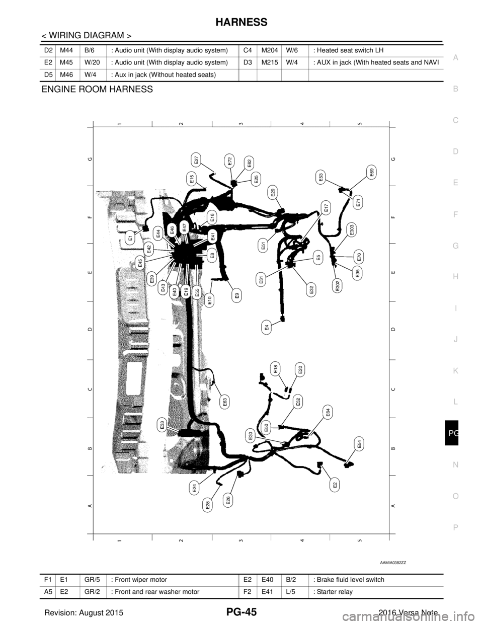
ENGINE ROOM HARNESS
D2 M44 B/6 : Audio unit (With display audio system) C4 M204
W/6 : Heated seat switch LH
E2 M45 W/20 : Audio unit (With display audio system) D3 M215 W/4 : AUX in jack (With heated seats and NAVI
D5 M46 W/4 : Aux in jack (Without heated seats)
AAMIA0382ZZ
F1 E1 GR/5 : Front wiper motor E2 E40 B/2 : Brake fluid level switch
A5 E2 GR/2 : Front and rear washer motor F2 E41 L/5 : Starter relay
Revision: August 2015 2016 Versa Note
cardiagn.com
Page 3566 of 3641

WW-1
DRIVER CONTROLS
C
DE
F
G H
I
J
K
M
SECTION WW
A
B
WW
N
O P
CONTENTS
WIPER & WASHER
PRECAUTION ....... ........................................3
PRECAUTIONS .............................................. .....3
Precaution for Supplemental Restraint System
(SRS) "AIR BAG" and "SEAT BELT PRE-TEN-
SIONER" ............................................................. ......
3
Procedure without Cowl Top Cover .......................3
Precaution for Work ..................................................3
PREPARATION ............................................5
PREPARATION .............................................. .....5
Special Service Tools .......................................... ......5
Commercial Service Tool ..........................................5
SYSTEM DESCRIPTION ..............................6
COMPONENT PARTS ................................... .....6
Component Parts Location .................................. ......6
SYSTEM ..............................................................8
FRONT WIPER AND WASHER SYSTEM ............. ......8
FRONT WIPER AND WASHER SYSTEM : Sys-
tem Diagram ..............................................................
8
FRONT WIPER AND WASHER SYSTEM : Sys-
tem Description .........................................................
8
FRONT WIPER AND WASHER SYSTEM : Fail-
Safe .........................................................................
10
REAR WIPER AND WASHER SYSTEM ............... ....10
REAR WIPER AND WASHER SYSTEM : System
Diagram ...................................................................
10
REAR WIPER AND WASHER SYSTEM : System
Description ..............................................................
10
DIAGNOSIS SYSTEM (BCM) (WITH INTELLI-
GENT KEY SYSTEM) .........................................
13
COMMON ITEM ..................................................... ....13
COMMON ITEM : CONSULT Function (BCM -
COMMON ITEM) .....................................................
13
WIPER .................................................................... ....14
WIPER : CONSULT Function (BCM - WIPER) .......14
DIAGNOSIS SYSTEM (BCM) (WITHOUT IN-
TELLIGENT KEY SYSTEM) .............................
15
COMMON ITEM ..................................................... ....15
COMMON ITEM : CONSULT Function (BCM -
COMMON ITEM) .....................................................
15
WIPER .................................................................... ....16
WIPER : CONSULT Function (BCM - WIPER) .......16
DIAGNOSIS SYSTEM (IPDM E/R) ...................17
Diagnosis Description ..............................................17
CONSULT Function (IPDM E/R) .............................18
ECU DIAGNOSIS INFORMATION ..............21
BCM, IPDM E/R .................................................21
List of ECU Reference ......................................... ....21
WIRING DIAGRAM ......................................22
FRONT WIPER AND WASHER SYSTEM ........22
Wiring Diagram .................................................... ....22
REAR WIPER AND WASHER SYSTEM ..........28
Wiring Diagram ........................................................28
BASIC INSPECTION ...................................33
DIAGNOSIS AND REPAIR WORKFLOW ........33
Work Flow ............................................................ ....33
DTC/CIRCUIT DIAGNOSIS .........................35
WIPER AND WASHER FUSE ...........................35
Description ........................................................... ....35
Diagnosis Procedure ...............................................35
FRONT WIPER MOTOR LO CIRCUIT ..............36
Component Function Check ....................................36
Diagnosis Procedure ...............................................36
Revision: August 2015 2016 Versa Note
cardiagn.com
Page 3567 of 3641

WW-2
FRONT WIPER MOTOR HI CIRCUIT ................38
Component Function Check ................................ ...38
Diagnosis Procedure ..............................................38
FRONT WIPER AUTO STOP SIGNAL CIR-
CUIT ...................................................................
40
Component Function Check ................................ ...40
Diagnosis Procedure ..............................................40
FRONT WIPER MOTOR GROUND CIRCUIT ...42
Diagnosis Procedure ..............................................42
WASHER MOTOR CIRCUIT .............................43
Diagnosis Procedure ........................................... ...43
WASHER SWITCH ............................................44
Description ........................................................... ...44
Component Inspection ............................................44
REAR WIPER MOTOR CIRCUIT ......................46
Component Function Check ................................ ...46
Diagnosis Procedure ..............................................46
REAR WIPER AUTO STOP SIGNAL CIRCUIT
...
48
Component Function Check ................................ ...48
Diagnosis Procedure ..............................................48
SYMPTOM DIAGNOSIS .............................50
WIPER AND WASHER SYSTEM SYMPTOMS
...
50
Symptom Table ................................................... ...50
FRONT WIPER DOES NOT OPERATE ............53
Description ........................................................... ...53
Diagnosis Procedure ..............................................53
NORMAL OPERATING CONDITION ................55
Description ........................................................... ...55
REMOVAL AND INSTALLATION ...............56
WASHER TANK ............................................. ...56
Exploded View ..................................................... ...56
Removal and Installation ........................................56
FRONT WASHER MOTOR ................................58
Exploded View ..................................................... ...58
Removal and Installation ........................................58
WASHER FLUID LEVEL SWITCH ....................59
Removal and Installation ..................................... ...59
FRONT WASHER NOZZLE AND TUBE ...........60
Exploded View ..................................................... ...60
WASHER NOZZLE ................................................. ...60
WASHER NOZZLE : Removal and Installation .......60
WASHER NOZZLE : Adjustment ............................61
WASHER TUBE ..................................................... ...61
WASHER TUBE : Removal and Installation ...........61
WASHER TUBE : Inspection ..................................62
FRONT WIPER ARM .........................................63
Exploded View ..................................................... ...63
Removal and Installation .........................................63
Adjustment ........................................................... ...64
FRONT WIPER BLADE .....................................65
Removal and Installation .........................................65
FRONT WIPER DRIVE ASSEMBLY .............. ...66
Exploded View ..................................................... ...66
Removal and Installation .........................................66
Exploded View ..................................................... ...67
Disassembly and Assembly ....................................67
WIPER AND WASHER SWITCH ......................68
Removal and Installation .........................................68
REAR WIPER ARM ........................................ ...69
Exploded View ..................................................... ...69
Removal and Installation .........................................69
Adjustment ........................................................... ...70
REAR WIPER BLADE .......................................71
Removal and Installation .........................................71
REAR WIPER MOTOR ................................... ...72
Exploded View ..................................................... ...72
Removal and Installation .........................................72
REAR WASHER NOZZLE AND TUBE .......... ...73
Component Parts Location .................................. ...73
WASHER NOZZLE ................................................. ...73
WASHER NOZZLE : Removal and Installation .......73
WASHER NOZZLE : Adjustment ............................73
WASHER TUBE ..................................................... ...74
WASHER TUBE : Removal and Installation ...........74
SERVICE DATA AND SPECIFICATIONS
(SDS) .......... ................................. ...............
76
SERVICE DATA AND SPECIFICATIONS
(SDS) .............................................................. ...
76
Specifications ....................................................... ...76
Revision: August 2015 2016 Versa Note
cardiagn.com
Page 3572 of 3641

COMPONENT PARTSWW-7
< SYSTEM DESCRIPTION >
C
DE
F
G H
I
J
K
M A
B
WW
N
O P
3. Washer fluid level switch (for
Canada) Transmits the washer fluid level switch signal to the combination meter.
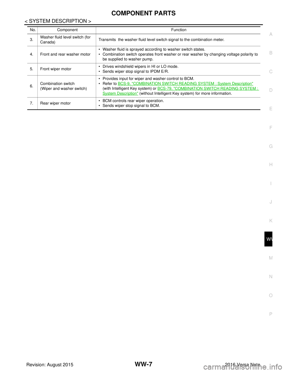
4. Front and rear washer motor • Washer fluid is sprayed according to washer switch states.
• Combination switch operates front washer or rear washer by changing voltage polarity to
be supplied to washer pump.
5. Front wiper motor • Drives windshield wipers in HI or LO mode.
• Sends wiper stop signal to IPDM E/R.
6. Combination switch
(Wiper and washer switch) • Provides input for wiper and washer control to BCM.
• Refer to
BCS-9, "
COMBINATION SWITCH READING SYSTEM : System Description"
(with Intelligent Key system) or BCS-79, "
COMBINATION SWITCH READING SYSTEM :
System Description" (without Intelligent Key system) for more information.
7. Rear wiper motor • BCM controls rear wiper operation.
• Sends wiper stop signal to BCM.
No.
Component Function
Revision: August 2015 2016 Versa Note
cardiagn.com
Page 3573 of 3641

WW-8
< SYSTEM DESCRIPTION >
SYSTEM
SYSTEM
FRONT WIPER AND WASHER SYSTEM
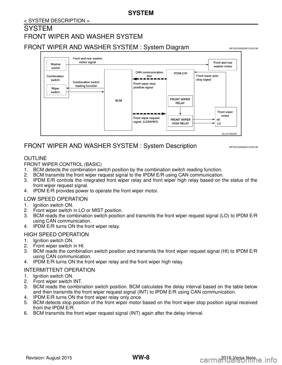
FRONT WIPER AND WASHER SYSTEM : System DiagramINFOID:0000000012433198
FRONT WIPER AND WASHER SYSTEM : System DescriptionINFOID:0000000012433199
OUTLINE
FRONT WIPER CONTROL (BASIC)
1. BCM detects the combination switch position by the combination switch reading function.
2. BCM transmits the front wiper request signal to the IPDM E/R using CAN communication.
3. IPDM E/R controls the integrated front wiper relay and front wiper high relay based on the status of the front wiper request signal.
4. IPDM E/R provides power to operate the front wiper motor.
LOW SPEED OPERATION
1. Ignition switch ON.
2. Front wiper switch in LO or MIST position.
3. BCM reads the combination switch position and transmi ts the front wiper request signal (LO) to IPDM E/R
using CAN communication.
4. IPDM E/R turns ON the front wiper relay.
HIGH SPEED OPERATION
1. Ignition switch ON.
2. Front wiper switch in HI.
3. BCM reads the combination switch position and transmits the front wiper request signal (HI) to IPDM E/R using CAN communication.
4. IPDM E/R turns ON the front wiper relay and the front wiper high relay.
INTERMITTENT OPERATION
1. Ignition switch ON.
2. Front wiper switch INT.
3. BCM reads the combination switch position. BCM ca lculates the delay interval based on the table below
and then transmits the front wiper request signal (INT) to IPDM E/R using CAN communication.
4. IPDM E/R turns ON the front wiper relay only once.
5. BCM detects stop position of the front wiper motor based on the front wiper stop position signal received from the IPDM E/R.
6. BCM transmits the front wiper request si gnal (INT) again after the delay interval.
ALLIA1550GB
Revision: August 2015 2016 Versa Note
cardiagn.com