2016 NISSAN NOTE front washer motor
[x] Cancel search: front washer motorPage 3615 of 3641
WW-50
< SYMPTOM DIAGNOSIS >
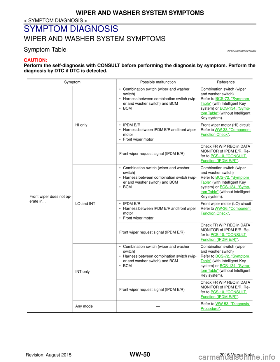
WIPER AND WASHER SYSTEM SYMPTOMS
SYMPTOM DIAGNOSIS
WIPER AND WASHER SYSTEM SYMPTOMS
Symptom TableINFOID:0000000012433229
CAUTION:
Perform the self-diagnosis with CONSULT before performing the diagnosis by symptom. Perform the
diagnosis by DTC if DTC is detected.
SymptomPossible malfunction Reference
Front wiper does not op-
erate in... HI only
• Combination switch (wiper and washer
switch)
• Harness between combination switch (wip- er and washer switch) and BCM
•BCM Combination switch (wiper
and washer switch)
Refer to BCS-72, "
Symptom
Ta b l e" (with Intelligent Key
system) or BCS-134, "
Symp-
tom Table" (without Intelligent
Key system).
• IPDM E/R
• Harness between IPDM E/R and front wiper motor
• Front wiper motor Front wiper motor (HI) circuit
Refer to WW-38, "
Component
Function Check".
Front wiper request signal (IPDM E/R) Check FR WIP REQ in DATA
MONITOR of IPDM E/R. Re-
fer to PCS-10, "
CONSULT
Function (IPDM E/R)".
LO and INT • Combination switch (wiper and washer
switch)
• Harness between combination switch (wip- er and washer switch) and BCM
•BCM Combination switch (wiper
and washer switch)
Refer to BCS-72, "
Symptom
Ta b l e" (with Intelligent Key
system) or BCS-134, "
Symp-
tom Table" (without Intelligent
Key system).
• IPDM E/R
• Harness between IPDM E/R and front wiper motor
• Front wiper motor Front wiper motor (LO) circuit
Refer to WW-36, "
Component
Function Check".
Front wiper request signal (IPDM E/R) Check FR WIP REQ in DATA
MONITOR of IPDM E/R. Re-
fer to PCS-10, "
CONSULT
Function (IPDM E/R)".
INT only • Combination switch (wiper and washer
switch)
• Harness between combination switch (wip- er and washer switch) and BCM
•BCM Combination switch (wiper
and washer switch)
Refer to BCS-72, "
Symptom
Ta b l e" (with Intelligent Key
system) or BCS-134, "
Symp-
tom Table" (without Intelligent
Key system).
Front wiper request signal (IPDM E/R) Check FR WIP REQ in DATA
MONITOR of IPDM E/R. Re-
fer to PCS-10, "
CONSULT
Function (IPDM E/R)".
Any mode —Refer to WW-53, "
Diagnosis
Procedure".
Revision: August 2015
2016 Versa Note
cardiagn.com
Page 3616 of 3641
WIPER AND WASHER SYSTEM SYMPTOMSWW-51
< SYMPTOM DIAGNOSIS >
C
DE
F
G H
I
J
K
M A
B
WW
N
O P
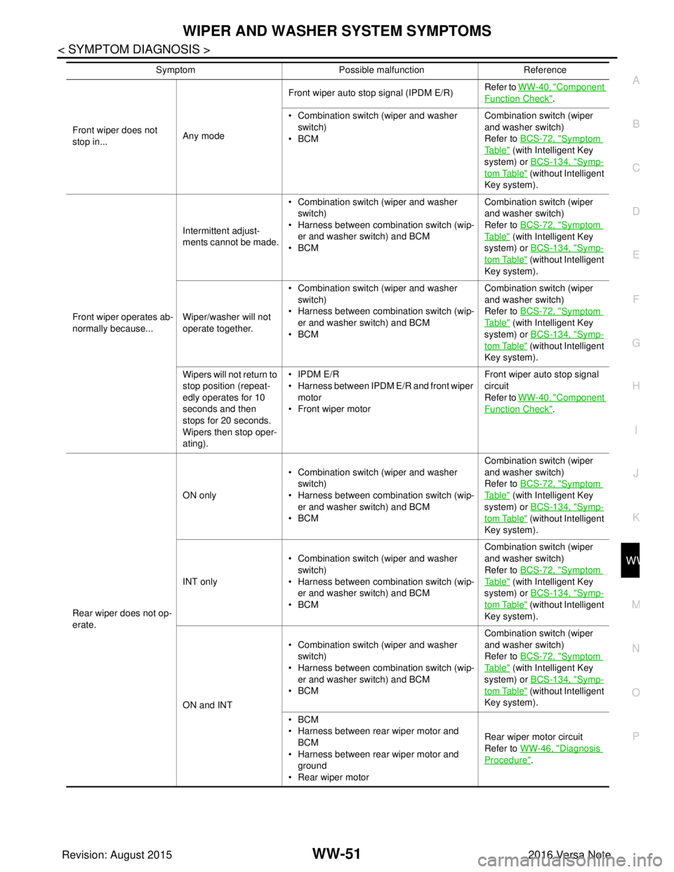
Front wiper does not
stop in... Any modeFront wiper auto stop signal (IPDM E/R)
Refer to
WW-40, "
Component
Function Check".
• Combination switch (wiper and washer switch)
•BCM Combination switch (wiper
and washer switch)
Refer to
BCS-72, "
Symptom
Ta b l e" (with Intelligent Key
system) or BCS-134, "
Symp-
tom Table" (without Intelligent
Key system).
Front wiper operates ab-
normally because... Intermittent adjust-
ments cannot be made.
• Combination switch (wiper and washer
switch)
• Harness between combination switch (wip- er and washer switch) and BCM
•BCM Combination switch (wiper
and washer switch)
Refer to
BCS-72, "
Symptom
Ta b l e" (with Intelligent Key
system) or BCS-134, "
Symp-
tom Table" (without Intelligent
Key system).
Wiper/washer will not
operate together. • Combination switch (wiper and washer
switch)
• Harness between combination switch (wip- er and washer switch) and BCM
•BCM Combination switch (wiper
and washer switch)
Refer to
BCS-72, "
Symptom
Ta b l e" (with Intelligent Key
system) or BCS-134, "
Symp-
tom Table" (without Intelligent
Key system).
Wipers will not return to
stop position (repeat-
edly operates for 10
seconds and then
stops for 20 seconds.
Wipers then stop oper-
ating). • IPDM E/R
• Harness between IPDM E/R and front wiper
motor
• Front wiper motor Front wiper auto stop signal
circuit
Refer to
WW-40, "
Component
Function Check".
Rear wiper does not op-
erate. ON only
• Combination switch (wiper and washer
switch)
• Harness between combination switch (wip-
er and washer switch) and BCM
•BCM Combination switch (wiper
and washer switch)
Refer to
BCS-72, "
Symptom
Ta b l e" (with Intelligent Key
system) or BCS-134, "
Symp-
tom Table" (without Intelligent
Key system).
INT only • Combination switch (wiper and washer
switch)
• Harness between combination switch (wip- er and washer switch) and BCM
•BCM Combination switch (wiper
and washer switch)
Refer to
BCS-72, "
Symptom
Ta b l e" (with Intelligent Key
system) or BCS-134, "
Symp-
tom Table" (without Intelligent
Key system).
ON and INT • Combination switch (wiper and washer
switch)
• Harness between combination switch (wip- er and washer switch) and BCM
•BCM Combination switch (wiper
and washer switch)
Refer to
BCS-72, "
Symptom
Ta b l e" (with Intelligent Key
system) or BCS-134, "
Symp-
tom Table" (without Intelligent
Key system).
•BCM
• Harness between rear wiper motor and BCM
• Harness between rear wiper motor and ground
• Rear wiper motor Rear wiper motor circuit
Refer to
WW-46, "
Diagnosis
Procedure".
Symptom
Possible malfunction Reference
Revision: August 2015 2016 Versa Note
cardiagn.com
Page 3617 of 3641
WW-52
< SYMPTOM DIAGNOSIS >
WIPER AND WASHER SYSTEM SYMPTOMS
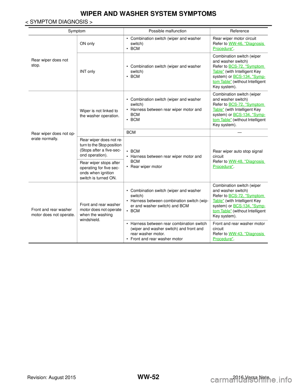
Rear wiper does not
stop.ON only
• Combination switch (wiper and washer
switch)
•BCM Rear wiper motor circuit
Refer to WW-46, "
Diagnosis
Procedure".
INT only • Combination switch (wiper and washer
switch)
•BCM Combination switch (wiper
and washer switch)
Refer to BCS-72, "
Symptom
Ta b l e" (with Intelligent Key
system) or BCS-134, "
Symp-
tom Table" (without Intelligent
Key system).
Rear wiper does not op-
erate normally. Wiper is not linked to
the washer operation.
• Combination switch (wiper and washer
switch)
• Harness between rear wiper motor and BCM
•BCM Combination switch (wiper
and washer switch)
Refer to BCS-72, "
Symptom
Ta b l e" (with Intelligent Key
system) or BCS-134, "
Symp-
tom Table" (without Intelligent
Key system).
BCM —
Rear wiper does not re-
turn to the Stop position
(Stops after a five-sec-
ond operation). •BCM
• Harness between rear wiper motor and
BCM
• Rear wiper motor Rear wiper auto stop signal
circuit
Refer to WW-48, "
Diagnosis
Procedure".
Rear wiper stops after
operating for five sec-
onds when ignition
switch is turned ON.
Front and rear washer
motor does not operate. Front and rear washer
motor does not operate
when the washing
windshield.• Combination switch (wiper and washer
switch)
• Harness between combination switch (wip- er and washer switch) and BCM
•BCM Combination switch (wiper
and washer switch)
Refer to BCS-72, "
Symptom
Ta b l e" (with Intelligent Key
system) or BCS-134, "
Symp-
tom Table" (without Intelligent
Key system).
• Harness between rear combination switch (wiper and washer switch) and front and
rear washer motor.
• Front and rear washer motor Front and rear washer motor
circuit
Refer to WW-43, "
Diagnosis
Procedure".
Symptom
Possible malfunction Reference
Revision: August 2015 2016 Versa Note
cardiagn.com
Page 3621 of 3641
WW-56
< REMOVAL AND INSTALLATION >
WASHER TANK
REMOVAL AND INSTALLATION
WASHER TANK
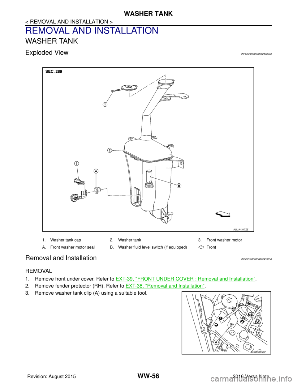
Exploded ViewINFOID:0000000012433233
Removal and InstallationINFOID:0000000012433234
REMOVAL
1. Remove front under cover. Refer to EXT-39, "FRONT UNDER COVER : Removal and Installation".
2. Remove fender protector (RH). Refer to EXT-38, "
Removal and Installation".
3. Remove washer tank clip (A) using a suitable tool.
1. Washer tank cap 2. Washer tank 3. Front washer motor
A. Front washer motor seal B. Washer fluid level switch (if equipped) Front
ALLIA1317ZZ
ALKIA3175ZZ
Revision: August 2015 2016 Versa Note
cardiagn.com
Page 3622 of 3641
WASHER TANKWW-57
< REMOVAL AND INSTALLATION >
C
DE
F
G H
I
J
K
M A
B
WW
N
O P
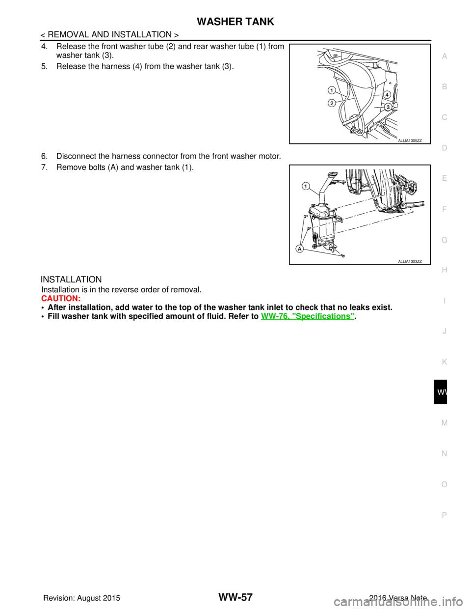
4. Release the front washer tube (2) and rear washer tube (1) from
washer tank (3).
5. Release the harness (4) from the washer tank (3).
6. Disconnect the harness connector from the front washer motor.
7. Remove bolts (A) and washer tank (1).
INSTALLATION
Installation is in the reverse order of removal.
CAUTION:
• After installation, add water to the top of th e washer tank inlet to check that no leaks exist.
• Fill washer tank with specified amount of fluid. Refer to WW-76, "
Specifications".
ALLIA1305ZZ
ALLIA1303ZZ
Revision: August 2015 2016 Versa Note
cardiagn.com
Page 3623 of 3641
WW-58
< REMOVAL AND INSTALLATION >
FRONT WASHER MOTOR
FRONT WASHER MOTOR
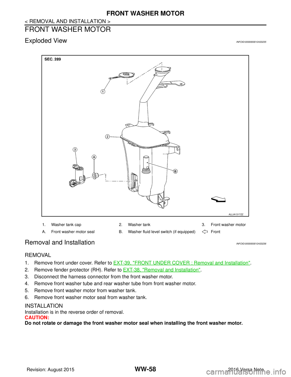
Exploded ViewINFOID:0000000012433235
Removal and InstallationINFOID:0000000012433236
REMOVAL
1. Remove front under cover. Refer to EXT-39, "FRONT UNDER COVER : Removal and Installation".
2. Remove fender protector (RH). Refer to EXT-38, "
Removal and Installation".
3. Disconnect the harness connector from the front washer motor.
4. Remove front washer tube and rear wa sher tube from front washer motor.
5. Remove front washer motor from washer tank.
6. Remove front washer motor seal from washer tank.
INSTALLATION
Installation is in the reverse order of removal.
CAUTION:
Do not rotate or damage the front washer moto r seal when installing the front washer motor.
1. Washer tank cap 2. Washer tank 3. Front washer motor
A. Front washer motor seal B. Washer fluid level switch (if equipped) Front
ALLIA1317ZZ
Revision: August 2015 2016 Versa Note
cardiagn.com
Page 3625 of 3641
WW-60
< REMOVAL AND INSTALLATION >
FRONT WASHER NOZZLE AND TUBE
FRONT WASHER NOZZLE AND TUBE
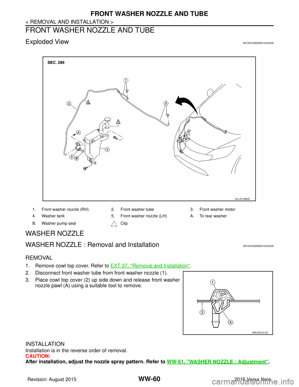
Exploded ViewINFOID:0000000012433238
WASHER NOZZLE
WASHER NOZZLE : Removal and InstallationINFOID:0000000012433239
REMOVAL
1. Remove cowl top cover. Refer to EXT-37, "Removal and Installation".
2. Disconnect front washer tube fr om front washer nozzle (1).
3. Place cowl top cover (2) up side down and release front washer nozzle pawl (A) using a suitable tool to remove.
INSTALLATION
Installation is in the reverse order of removal.
CAUTION:
After installation, adjust the nozzle spray pattern. Refer to WW-61, "
WASHER NOZZLE : Adjustment".
1. Front washer nozzle (RH) 2. Front washer tube3. Front washer motor
4. Washer tank 5. Front washer nozzle (LH) A. To rear washer
B. Washer pump seal Clip
ALLIA1306ZZ
AWLIA2161ZZ
Revision: August 2015 2016 Versa Note
cardiagn.com
Page 3638 of 3641
REAR WASHER NOZZLE AND TUBEWW-73
< REMOVAL AND INSTALLATION >
C
DE
F
G H
I
J
K
M A
B
WW
N
O P
REAR WASHER NOZZLE AND TUBE
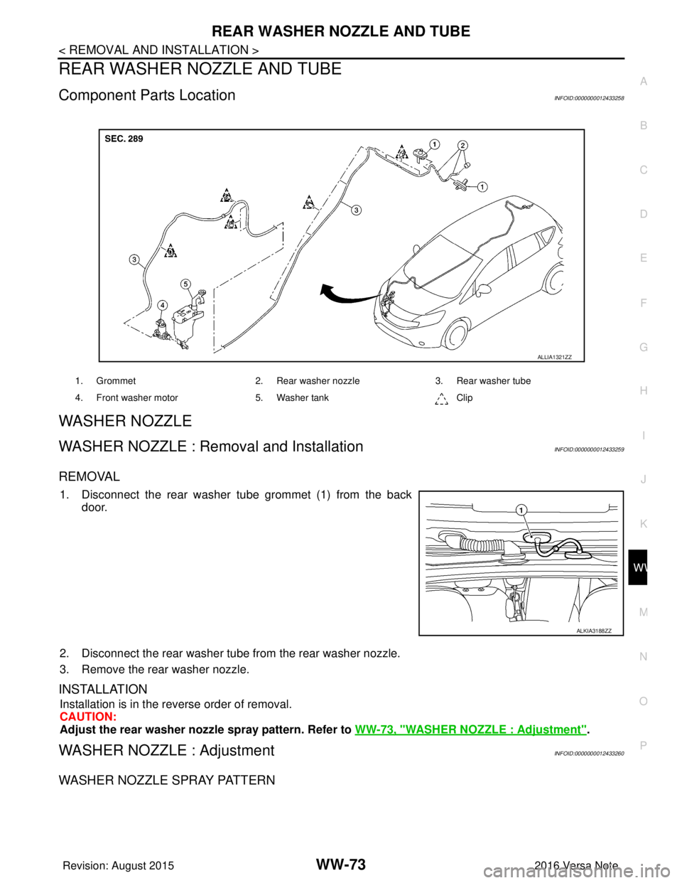
Component Parts LocationINFOID:0000000012433258
WASHER NOZZLE
WASHER NOZZLE : Removal and InstallationINFOID:0000000012433259
REMOVAL
1. Disconnect the rear washer tube grommet (1) from the back door.
2. Disconnect the rear washer tube from the rear washer nozzle.
3. Remove the rear washer nozzle.
INSTALLATION
Installation is in the reverse order of removal.
CAUTION:
Adjust the rear washer nozz le spray pattern. Refer to WW-73, "
WASHER NOZZLE : Adjustment".
WASHER NOZZLE : AdjustmentINFOID:0000000012433260
WASHER NOZZLE SPRAY PATTERN
1. Grommet 2. Rear washer nozzle3. Rear washer tube
4. Front washer motor 5. Washer tank Clip
ALLIA1321ZZ
ALKIA3188ZZ
Revision: August 2015 2016 Versa Note
cardiagn.com