2016 NISSAN NOTE adding oil
[x] Cancel search: adding oilPage 1058 of 3641
![NISSAN NOTE 2016 Service Repair Manual TIMING CHAINEM-57
< REMOVAL AND INSTALLATION > [HR16DE]
C
D
E
F
G H
I
J
K L
M A
EM
NP
O
3. Install timing chain tension guide (2) and timing chain slack
guide (1).
4. Install chain tensioner (1). • NISSAN NOTE 2016 Service Repair Manual TIMING CHAINEM-57
< REMOVAL AND INSTALLATION > [HR16DE]
C
D
E
F
G H
I
J
K L
M A
EM
NP
O
3. Install timing chain tension guide (2) and timing chain slack
guide (1).
4. Install chain tensioner (1). •](/manual-img/5/57363/w960_57363-1057.png)
TIMING CHAINEM-57
< REMOVAL AND INSTALLATION > [HR16DE]
C
D
E
F
G H
I
J
K L
M A
EM
NP
O
3. Install timing chain tension guide (2) and timing chain slack
guide (1).
4. Install chain tensioner (1). • Secure the plunger at the most compressed position using a
stopper pin (A), and then install it.
• Pull out the stopper pin after installing the chain tensioner.
5. Check matching mark position of timing chain and each sprocket again.
6. Install the front oil seal to the front cover. Refer to EM-74, "
FRONT OIL SEAL : Removal and Installation".
7. Install front cover with the following procedure:
a. Apply a continuous bead of liquid gasket to the engine block joint locations (A) as shown. Use Genuine Silicone RTV Sealant or equivalent. Refer to GI-22, "
Recommended Chemical Products
and Sealants"
CAUTION:
• Do not confirm torque after the 5 minutes have elapsed.
• Then allow 30 minutes for the liquid gasket to set before
adding oil to the engine.
b. Apply a continuous bead of liquid gasket to front cover as shown using suitable tool. Use Genuine Silicone RTV Sealant or equivalent. Refer to GI-22, "
Recommended Chemical Products
and Sealants".
JPBIA4141ZZ
PBIC3722E
(1) : Cylinder head
(2) : Cylinder block
(3) : Oil pan (upper)
(A) : Liquid gasket application area [3.0 - 4.0 mm (0.12 - 0.16 in) diam-
eter]
JPBIA4145ZZ
Revision: August 2015 2016 Versa Note
cardiagn.com
Page 1059 of 3641
![NISSAN NOTE 2016 Service Repair Manual EM-58
< REMOVAL AND INSTALLATION >[HR16DE]
TIMING CHAIN
CAUTION:
• Do not confirm torque afte
r the 5 minutes have elapsed.
• Then allow 30 minutes for the liquid gasket to set before
adding oil t NISSAN NOTE 2016 Service Repair Manual EM-58
< REMOVAL AND INSTALLATION >[HR16DE]
TIMING CHAIN
CAUTION:
• Do not confirm torque afte
r the 5 minutes have elapsed.
• Then allow 30 minutes for the liquid gasket to set before
adding oil t](/manual-img/5/57363/w960_57363-1058.png)
EM-58
< REMOVAL AND INSTALLATION >[HR16DE]
TIMING CHAIN
CAUTION:
• Do not confirm torque afte
r the 5 minutes have elapsed.
• Then allow 30 minutes for the liquid gasket to set before
adding oil to the engine.
c. Tighten bolts in the numerical order as shown. NOTE:
Refer to the following for the installation position of bolts.
d. After all bolts are tightened, retighten them to specified torque in numerical order as shown.
CAUTION:
Be sure to wipe off any excessive liquid gasket leaking to
surface.
8. Insert crankshaft pulley by aligning with crankshaft key. • When inserting crankshaft pulley with a plastic hammer, tap on its center portion (not circumference).CAUTION:
Do not damage front oil seal lip section.
9. Tighten crankshaft pulley bolt:
(1) : Front cover edge
(A) : Liquid gasket application area
(b) : 4.0 - 5.6 mm
(c) : Liquid gasket application area [3.0 - 4.0 mm (0.12 - 0.16 in) diame-
ter]
JPBIA4146ZZ
M6 bolt : No. 1
6.6 N·m (0.67 kg-m,
58 in-lb)
M10 bolts : No. 11, 12, 13 55.0 N·m (5.6 kg-m, 41 ft-lb)
M10 bolts : No. 14, 15 55.0 N·m (5.6 kg-m, 41 ft-lb)
M8 bolts : Except above 25.0 N·m (2.6 kg-m, 18 ft-lb)
JPBIA4139ZZ
Revision: August 2015 2016 Versa Note
cardiagn.com
Page 2327 of 3641

MA-12
< PERIODIC MAINTENANCE >
RECOMMENDED FLUIDS AND LUBRICANTS
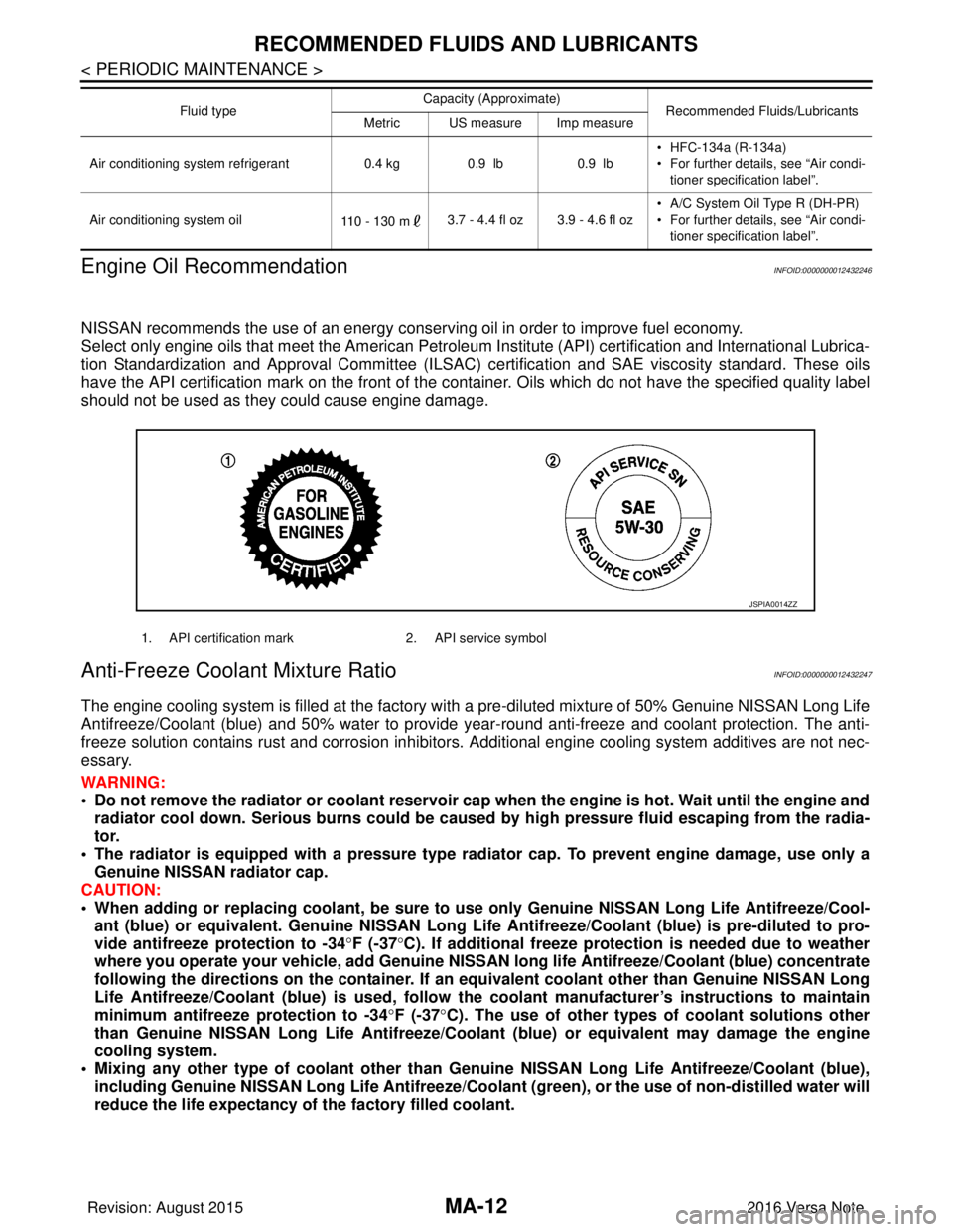
Engine Oil Recommendation
INFOID:0000000012432246
NISSAN recommends the use of an energy conservi ng oil in order to improve fuel economy.
Select only engine oils that meet the American Petroleum Institute (API) certification and International Lubrica-
tion Standardization and Approval Committee (ILSAC) ce rtification and SAE viscosity standard. These oils
have the API certification mark on the front of the container. Oils whic h do not have the specified quality label
should not be used as they could cause engine damage.
Anti-Freeze Coolant Mixture RatioINFOID:0000000012432247
The engine cooling system is filled at the factory with a pre-diluted mixture of 50% Genuine NISSAN Long Life
Antifreeze/Coolant (blue) and 50% water to provide year-round anti-freeze and coolant protection. The anti-
freeze solution contains rust and corrosion inhibitors. Additional engine cooling system additives are not nec-
essary.
WARNING:
• Do not remove the radiator or coolant reservoir cap when the engine is hot. Wait until the engine and radiator cool down. Serious burns could be caused by high pressure fluid escaping from the radia-
tor.
• The radiator is equipped with a pressure type radiator cap. To prevent engine damage, use only a
Genuine NISSAN radiator cap.
CAUTION:
• When adding or replacing coolant, be sure to use only Genuine NISSAN Lo ng Life Antifreeze/Cool-
ant (blue) or equivalent. Genuine NISSAN Long Life Antifreeze/Coolant (blue) is pre-diluted to pro-
vide antifreeze protection to -34 °F (-37 °C). If additional freeze protect ion is needed due to weather
where you operate your vehicle, add Genuine NISSAN long life Antifreeze/Coolant (blue) concentrate
following the directions on the container. If an equivalent coolant other than Genuine NISSAN Long
Life Antifreeze/Coolant (blue) is used, follow the coolant manufact urer’s instructions to maintain
minimum antifreeze protection to -34 °F (-37 °C). The use of other types of coolant solutions other
than Genuine NISSAN Long Life Antifreeze/Coolant (blue) or equivalent may damage the engine
cooling system.
• Mixing any other type of coolant other than Genuine NISSAN Long Life Antifreeze/Coolant (blue),
including Genuine NISSAN Long Life Antifreeze/Coolant (green), or the use of non-distilled water will
reduce the life expectancy of the factory filled coolant.
Air conditioning system refrigerant 0.4 kg0.9 lb 0.9 lb• HFC-134a (R-134a)
• For further details, see “Air condi-
tioner specification label”.
Air conditioning system oil 110 - 130 m3.7 - 4.4 fl oz 3.9 - 4.6 fl oz • A/C System Oil Type R (DH-PR)
• For further details, see “Air condi-
tioner specification label”.
Fluid type
Capacity (Approximate)
Recommended Fluids/Lubricants
Metric US measure Imp measure
1. API certification mark 2. API service symbol
JSPIA0014ZZ
Revision: August 2015 2016 Versa Note
cardiagn.com
Page 2347 of 3641

MA-32
< PERIODIC MAINTENANCE >
CHASSIS AND BODY MAINTENANCE
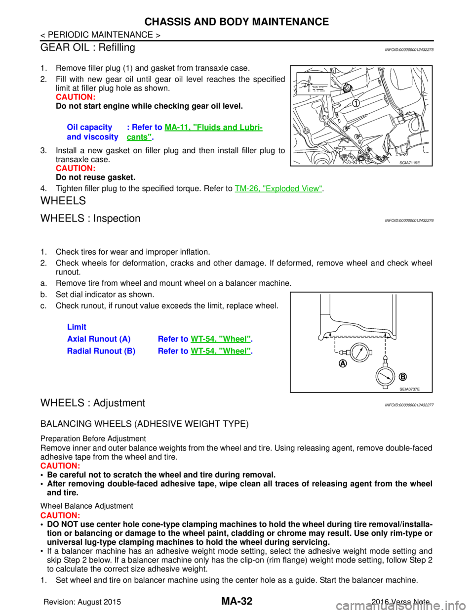
GEAR OIL : Refilling
INFOID:0000000012432275
1. Remove filler plug (1) and gasket from transaxle case.
2. Fill with new gear oil until gear oil level reaches the specified limit at filler plug hole as shown.
CAUTION:
Do not start engine whil e checking gear oil level.
3. Install a new gasket on filler plug and then install filler plug to transaxle case.
CAUTION:
Do not reuse gasket.
4. Tighten filler plug to the specified torque. Refer to TM-26, "
Exploded View".
WHEELS
WHEELS : InspectionINFOID:0000000012432276
1. Check tires for wear and improper inflation.
2. Check wheels for deformation, cracks and other dam age. If deformed, remove wheel and check wheel
runout.
a. Remove tire from wheel and mount wheel on a balancer machine.
b. Set dial indicator as shown.
c. Check runout, if runout value exceeds the limit, replace wheel.
WHEELS : AdjustmentINFOID:0000000012432277
BALANCING WHEELS (ADHESIVE WEIGHT TYPE)
Preparation Before Adjustment
Remove inner and outer balance weights from the wheel and tire. Using releasing agent, remove double-faced
adhesive tape from the wheel and tire.
CAUTION:
• Be careful not to scratch the wheel and tire during removal.
• After removing double-faced adh esive tape, wipe clean all traces of releasing agent from the wheel
and tire.
Wheel Balance Adjustment
CAUTION:
• DO NOT use center hole cone-type clamping machines to hold the wheel during tire removal/installa-
tion or balancing or damage to the wheel paint, cladding or chrome may result. Use only rim-type or
universal lug-type clamping machines to hold the wheel during servicing.
• If a balancer machine has an adhesive weight mode se tting, select the adhesive weight mode setting and
skip Step 2 below. If a balancer machine only has the clip -on (rim flange) weight mode setting, follow Step 2
to calculate the correct size adhesive weight.
1. Set wheel and tire on balancer machine using the center hole as a guide. Start the balancer machine. Oil capacity
and viscosity
: Refer to
MA-11, "
Fluids and Lubri-
cants".
SCIA7119E
Limit
Axial Runout (A) Refer to WT-54, "
Wheel".
Radial Runout (B) Refer to WT-54, "
Wheel".
SEIA0737E
Revision: August 2015 2016 Versa Note
cardiagn.com