2016 NISSAN NOTE washer pump
[x] Cancel search: washer pumpPage 1035 of 3641
![NISSAN NOTE 2016 Service Repair Manual EM-34
< REMOVAL AND INSTALLATION >[HR16DE]
OIL PAN AND OIL STRAINER
OIL PAN AND OIL STRAINER
Exploded ViewINFOID:0000000012431709
Removal and Installation (Lower Oil Pan)INFOID:0000000012431710
REMOVA NISSAN NOTE 2016 Service Repair Manual EM-34
< REMOVAL AND INSTALLATION >[HR16DE]
OIL PAN AND OIL STRAINER
OIL PAN AND OIL STRAINER
Exploded ViewINFOID:0000000012431709
Removal and Installation (Lower Oil Pan)INFOID:0000000012431710
REMOVA](/manual-img/5/57363/w960_57363-1034.png)
EM-34
< REMOVAL AND INSTALLATION >[HR16DE]
OIL PAN AND OIL STRAINER
OIL PAN AND OIL STRAINER
Exploded ViewINFOID:0000000012431709
Removal and Installation (Lower Oil Pan)INFOID:0000000012431710
REMOVAL
WARNING:
• Be careful not to get bu
rned, engine coolant and engine oil may be hot.
• Prolonged and repeated contact with used engi ne oil may cause skin cancer; avoid direct skin con-
tact with used oil. If skin contact is made, wash thoroughly with soap or hand cleaner as soon as
possible.
1. Drain engine oil. Refer to LU-8, "
Draining".
1. Rear oil seal 2. O-ring 3. Oil pan (upper)
4. Oil pump chain tensioner (for oil pump drive chain) 5. Oil pump drive chain
6. Crankshaft key
7. Crankshaft sprocket 8. Oil pump sprocket9. Oil pump
10. O-ring 11. O-ring 12. Oil pan drain plug
13. Drain plug washer 14. Oil pan (lower) 15. Oil filter
16. Connector bolt 17. Oil cooler 18. O-ring
19. Relief valve A. Refer to EM-37, "
Removal and In-
stallation (Upper Oil Pan)"
B. Refer to LU-10, "Removal and Instal-
lation"
C. Oil pan (lower) side
AWBIA1595ZZ
Revision: August 2015 2016 Versa Note
cardiagn.com
Page 1038 of 3641
![NISSAN NOTE 2016 Service Repair Manual OIL PAN AND OIL STRAINEREM-37
< REMOVAL AND INSTALLATION > [HR16DE]
C
D
E
F
G H
I
J
K L
M A
EM
NP
O
• Summary of the inspection items:
*Power steering fluid, brake fluid, etc.
Removal and Installati NISSAN NOTE 2016 Service Repair Manual OIL PAN AND OIL STRAINEREM-37
< REMOVAL AND INSTALLATION > [HR16DE]
C
D
E
F
G H
I
J
K L
M A
EM
NP
O
• Summary of the inspection items:
*Power steering fluid, brake fluid, etc.
Removal and Installati](/manual-img/5/57363/w960_57363-1037.png)
OIL PAN AND OIL STRAINEREM-37
< REMOVAL AND INSTALLATION > [HR16DE]
C
D
E
F
G H
I
J
K L
M A
EM
NP
O
• Summary of the inspection items:
*Power steering fluid, brake fluid, etc.
Removal and Installation (Upper Oil Pan)INFOID:0000000012431711
NOTE:
The oil strainer is included in the oil pan (upper) and cannot be removed.
REMOVAL
1. Remove the oil pan (lower). Refer to
EM-34, "Removal and Installation (Lower Oil Pan)".
2. Remove oil pump sprocket and crankshaft sprocket together with oil pump drive chain. Refer to EM-51,
"Removal and Installation".
3. Remove oil pan (upper).
a. Loosen oil pan (upper) bolts in the reverse of the order as shown.
b. Insert a suitable tool into the position ( ) as shown and open up a crack between the oil pan (upper) cylinder block.
c. Insert the Tool between the oil pan (upper) and cylinder block. Slide Tool by tapping on the side of Tool with a hammer.
CAUTION:
• Be careful not to damage the mating surface.
• The liquid gasket used at the factory is very strong. Pry only in the areas shown.
• Do not remove oil pump and oil strainer from oil pan (upper).
4. Remove rear oil seal from crankshaft.
INSTALLATION
CAUTION:
Do not reuse O-rings or washers.
1. Install the oil pan (upper):
a. Remove old liquid gasket from mating surfaces using a suitable tool. • Remove old liquid gasket from mating surface of cylinder block.
• Remove old liquid gasket from the bolt holes and threads.
Item Before starting engine Engine runningAfter engine stopped
Engine coolant LevelLeakage Level
Engine oil LevelLeakage Level
Transmission/
transaxle fluid CVT Models
LeakageLevel/Leakage Leakage
M/T Models Level/Leakage LeakageLevel/Leakage
Other oils and fluids* LevelLeakage Level
Fuel LeakageLeakageLeakage
Exhaust gas —Leakage —
: Engine front
JPBIA4199ZZ
: Engine front
Tool number : KV10111100 (J-37228)
JPBIA4200ZZ
Revision: August 2015 2016 Versa Note
cardiagn.com
Page 1638 of 3641
![NISSAN NOTE 2016 Service Repair Manual LU-8
< PERIODIC MAINTENANCE >[HR16DE]
ENGINE OIL
2. Disconnect harness connector at
oil pressure sensor. Remove
oil pressure sensor using suitable tool and install suitable tools
(A/B).
CAUTION:
Do n NISSAN NOTE 2016 Service Repair Manual LU-8
< PERIODIC MAINTENANCE >[HR16DE]
ENGINE OIL
2. Disconnect harness connector at
oil pressure sensor. Remove
oil pressure sensor using suitable tool and install suitable tools
(A/B).
CAUTION:
Do n](/manual-img/5/57363/w960_57363-1637.png)
LU-8
< PERIODIC MAINTENANCE >[HR16DE]
ENGINE OIL
2. Disconnect harness connector at
oil pressure sensor. Remove
oil pressure sensor using suitable tool and install suitable tools
(A/B).
CAUTION:
Do not drop or shock oil pressure sensor.
3. Start engine and warm it up to normal operating temperature.
4. Check engine oil pressure with engine running under no-load. NOTE:
• When engine oil temperature is low, engine oil pressure becomes high.
• If difference is extreme, check oil passage and oil pump for engine oil leaks.
5. After the inspections, install oil pressure sensor as follows:
a. Remove old liquid gasket adhering to oil pressure sensor and engine.
b. Apply liquid gasket and tighten oil pressure sensor to specification. Use Genuine Liquid Gasket or equivalent. Refer to GI-22, "
Recommended Chemical Products and
Sealants".
6. Check engine oil level.
7. After warming up engine, check that ther e is no engine oil leaks with the running engine.
DrainingINFOID:0000000012432201
WARNING:
• Be careful not to get burned, as engine oil may be hot.
• Prolonged and repeated contact with used engine oil may cause ski n cancer. Try to avoid direct skin
contact with used engine oil. If skin contact is made, wash thoroughly with soap or hand cleaner as
soon as possible.
1. Warm up the engine, park the vehicle on a level surface and check for engine oil leaks. Refer to LU-7,
"Inspection".
2. Stop the engine and wait for 10 minutes.
3. Loosen oil filler cap.
4. Remove drain plug and then drain engine oil.
RefillingINFOID:0000000012432202
1. Install drain plug with new copper sealing washer. Refer to EM-34, "Exploded View".
CAUTION:
• Be sure to clean drain plug.
• Do not reuse copper sealing washer.
2. Refill with new engine oil.
CAUTION:
• The refill capacity depends on the engine oi l temperature and drain time. Use these specifica-
tions for reference only.
• Always use oil level gauge to determine the pr oper amount of engine oil in the engine.
JPBIA0074ZZ
Engine oil pressure : Refer to LU-15, "Engine Oil Pressure".
Tightening torque : Refer to EM-93, "
Exploded View".
Engine oil capacity and viscosity : Refer to MA-11, "
Fluids and Lubricants".
Revision: August 2015 2016 Versa Note
cardiagn.com
Page 1641 of 3641
![NISSAN NOTE 2016 Service Repair Manual OIL PUMPLU-11
< REMOVAL AND INSTALLATION > [HR16DE]
C
D
E
F
G H
I
J
K L
M A
LU
NP
O
REMOVAL AND INSTALLATION
OIL PUMP
Exploded ViewINFOID:0000000012432204
Removal and InstallationINFOID:00000000124322 NISSAN NOTE 2016 Service Repair Manual OIL PUMPLU-11
< REMOVAL AND INSTALLATION > [HR16DE]
C
D
E
F
G H
I
J
K L
M A
LU
NP
O
REMOVAL AND INSTALLATION
OIL PUMP
Exploded ViewINFOID:0000000012432204
Removal and InstallationINFOID:00000000124322](/manual-img/5/57363/w960_57363-1640.png)
OIL PUMPLU-11
< REMOVAL AND INSTALLATION > [HR16DE]
C
D
E
F
G H
I
J
K L
M A
LU
NP
O
REMOVAL AND INSTALLATION
OIL PUMP
Exploded ViewINFOID:0000000012432204
Removal and InstallationINFOID:0000000012432205
NOTE:
When removing components such as hoses, tubes/lines, etc.
, cap or plug openings to prevent fluid from spill-
ing.
REMOVAL
1. Drain engine oil. Refer to LU-8, "Draining".
2. Remove timing chain and oil pump drive chain. Refer to EM-51, "
Removal and Installation".
1. Rear oil seal2. O-ring3. Oil pan (upper)
4. Oil pump chain tensioner (for oil pump drive chain) 5. Oil pump drive chain
6. Crankshaft key
7. Crankshaft sprocket 8. Oil pump sprocket9. Oil pump
10. O-ring 11. O-ring12. Oil pan drain plug
13. Drain plug washer 14. Oil pan (lower)15. Oil filter
16. Connector bolt 17. Oil cooler18. O-ring
19. Relief valve A. Refer to EM-51
B. Refer to LU-10
C. Oil pan (lower) side
AWBIA1595ZZ
Revision: August 2015 2016 Versa Note
cardiagn.com
Page 1912 of 3641

GI-24
< PRECAUTION >
PRECAUTIONS
General Precautions
INFOID:0000000012433162
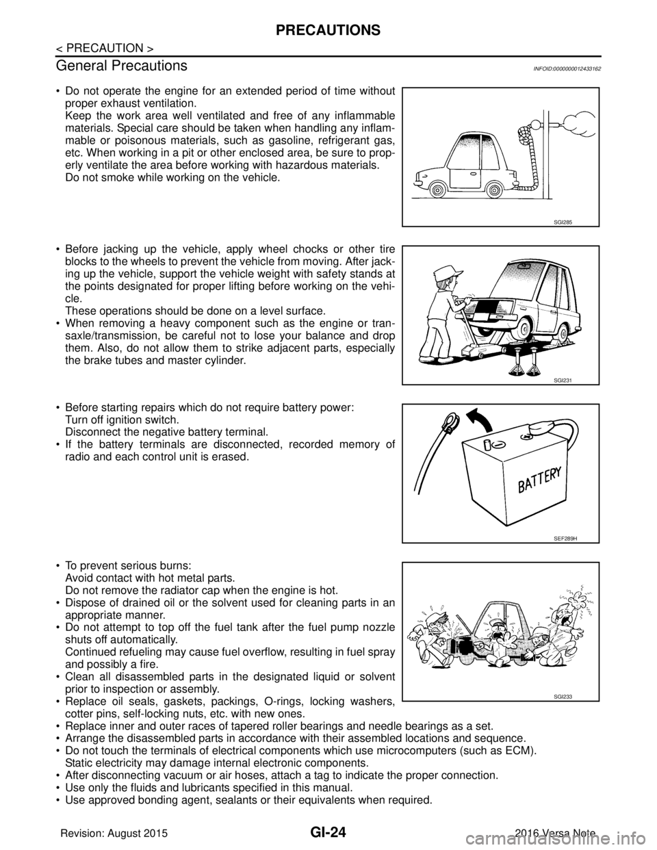
• Do not operate the engine for an extended period of time without proper exhaust ventilation.
Keep the work area well ventilated and free of any inflammable
materials. Special care should be taken when handling any inflam-
mable or poisonous materials, such as gasoline, refrigerant gas,
etc. When working in a pit or other enclosed area, be sure to prop-
erly ventilate the area before working with hazardous materials.
Do not smoke while working on the vehicle.
• Before jacking up the vehicle, apply wheel chocks or other tire blocks to the wheels to prevent the vehicle from moving. After jack-
ing up the vehicle, support the vehicle weight with safety stands at
the points designated for proper lifting before working on the vehi-
cle.
These operations should be done on a level surface.
• When removing a heavy component such as the engine or tran- saxle/transmission, be careful not to lose your balance and drop
them. Also, do not allow them to strike adjacent parts, especially
the brake tubes and master cylinder.
• Before starting repairs which do not require battery power: Turn off ignition switch.
Disconnect the negative battery terminal.
• If the battery terminals are disconnected, recorded memory of radio and each control unit is erased.
• To prevent serious burns: Avoid contact with hot metal parts.
Do not remove the radiator cap when the engine is hot.
• Dispose of drained oil or the solvent used for cleaning parts in an appropriate manner.
• Do not attempt to top off the fuel tank after the fuel pump nozzle
shuts off automatically.
Continued refueling may cause fuel overflow, resulting in fuel spray
and possibly a fire.
• Clean all disassembled parts in the designated liquid or solvent prior to inspection or assembly.
• Replace oil seals, gaskets, packings, O-rings, locking washers,
cotter pins, self-locking nuts, etc. with new ones.
• Replace inner and outer races of tapered roller bearings and needle bearings as a set.
• Arrange the disassembled parts in accordance with their assembled locations and sequence.
• Do not touch the terminals of electrical com ponents which use microcomputers (such as ECM).
Static electricity may damage internal electronic components.
• After disconnecting vacuum or air hoses, atta ch a tag to indicate the proper connection.
• Use only the fluids and lubricants specified in this manual.
• Use approved bonding agent, sealants or their equivalents when required.
SGI285
SGI231
SEF289H
SGI233
Revision: August 2015 2016 Versa Note
cardiagn.com
Page 2336 of 3641

ENGINE MAINTENANCEMA-21
< PERIODIC MAINTENANCE >
C
DE
F
G H
I
J
K L
M B
MA
N
O A
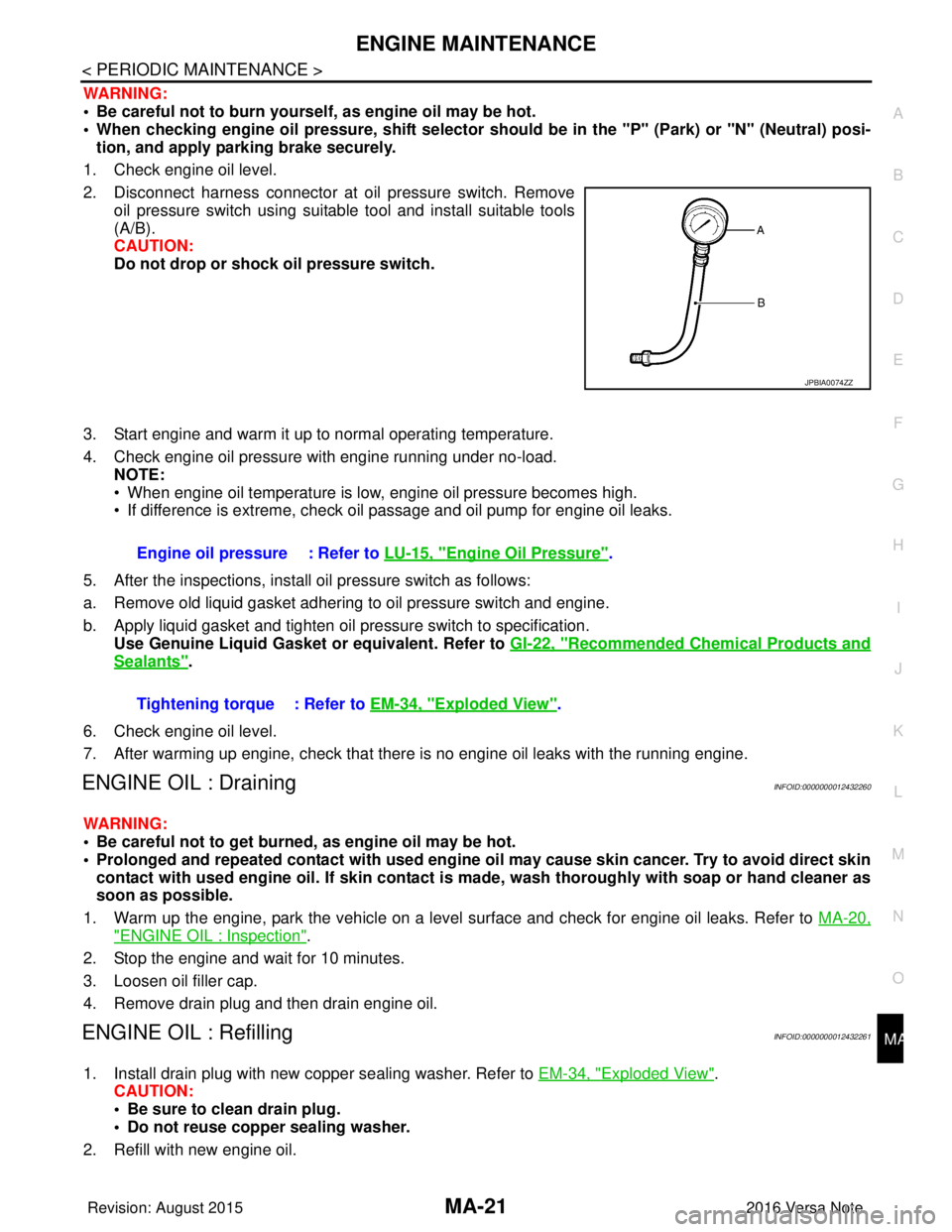
WARNING:
• Be careful not to burn yoursel
f, as engine oil may be hot.
• When checking engine oil pressure, sh ift selector should be in the "P" (Park) or "N" (Neutral) posi-
tion, and apply parking brake securely.
1. Check engine oil level.
2. Disconnect harness connector at oil pressure switch. Remove oil pressure switch using suitable tool and install suitable tools
(A/B).
CAUTION:
Do not drop or shock oil pressure switch.
3. Start engine and warm it up to normal operating temperature.
4. Check engine oil pressure with engine running under no-load. NOTE:
• When engine oil temperature is low, engine oil pressure becomes high.
• If difference is extreme, check oil passage and oil pump for engine oil leaks.
5. After the inspections, install oil pressure switch as follows:
a. Remove old liquid gasket adhering to oil pressure switch and engine.
b. Apply liquid gasket and tighten oil pressure switch to specification. Use Genuine Liquid Gasket or equivalent. Refer to GI-22, "
Recommended Chemical Products and
Sealants".
6. Check engine oil level.
7. After warming up engine, check that there is no engine oil leaks with the running engine.
ENGINE OIL : DrainingINFOID:0000000012432260
WARNING:
• Be careful not to get burned, as engine oil may be hot.
• Prolonged and repeated contact with used engine oil may cause skin cancer. Try to avoid direct skin
contact with used engine oil. If skin contact is made, wash thorough ly with soap or hand cleaner as
soon as possible.
1. Warm up the engine, park the vehicle on a level surface and check for engine oil leaks. Refer to MA-20,
"ENGINE OIL : Inspection".
2. Stop the engine and wait for 10 minutes.
3. Loosen oil filler cap.
4. Remove drain plug and then drain engine oil.
ENGINE OIL : RefillingINFOID:0000000012432261
1. Install drain plug with new copper sealing washer. Refer to EM-34, "Exploded View".
CAUTION:
• Be sure to clean drain plug.
• Do not reuse copper sealing washer.
2. Refill with new engine oil.
JPBIA0074ZZ
Engine oil pressure : Refer to LU-15, "Engine Oil Pressure".
Tightening torque : Refer to EM-34, "
Exploded View".
Revision: August 2015 2016 Versa Note
cardiagn.com
Page 2417 of 3641
![NISSAN NOTE 2016 Service Repair Manual MWI
COMPONENT PARTSMWI-59
< SYSTEM DESCRIPTION > [TYPE B]
C
D
E
F
G H
I
J
K L
M B A
O P
METER SYSTEM : Combination MeterINFOID:0000000012432600
The combination meter controls the following items a cco NISSAN NOTE 2016 Service Repair Manual MWI
COMPONENT PARTSMWI-59
< SYSTEM DESCRIPTION > [TYPE B]
C
D
E
F
G H
I
J
K L
M B A
O P
METER SYSTEM : Combination MeterINFOID:0000000012432600
The combination meter controls the following items a cco](/manual-img/5/57363/w960_57363-2416.png)
MWI
COMPONENT PARTSMWI-59
< SYSTEM DESCRIPTION > [TYPE B]
C
D
E
F
G H
I
J
K L
M B A
O P
METER SYSTEM : Combination MeterINFOID:0000000012432600
The combination meter controls the following items a ccording to the signals received from each unit via CAN
communication and the signals from switches and sensors:
• Measuring instruments
• Indicator lamps
• Warning lamps
• Meter illumination control
• Information display
ARRANGEMENT OF COMBINATION METER
3. Washer fluid level switch Transmits the washer fluid level switch signal to the combination meter (for Cana-
da).
Refer to
WW-6, "
Component Parts Location" for detailed installation location.
4. Engine oil pressure sensor Transmits the engine oil pressure sensor signal to the ECM.
Refer to
EM-93, "
Exploded View" for detailed installation location.
5. Ambient sensor Transmits the ambient sensor signal to the combination meter.
6. TCM Transmits the shift position signal to the combination meter via CAN communica-
tion (with CVT).
Refer to
TM-61, "
CVT CONTROL SYSTEM : Component Parts Location" for de-
tailed installation location.
7. ECM Transmits the following signals to the combination meter via CAN communication:
• Engine speed signal
• Engine coolant temperature signal
• Fuel consumption monitor signal
• Engine oil pressure sensor signal
Refer to
EC-14, "
ENGINE CONTROL SYSTEM : ComponentPartsLocation" for
detailed installation location.
8. BCM Transmits the following signals to the combination meter via CAN communication:
• Door switch signal
• Buzzer signal
Refer to
BCS-6, "
BODY CONTROL SYSTEM : Component Parts Location" (with
Intelligent Key system) or BCS-77, "
BODY CONTROL SYSTEM : Component
Parts Location" (without Intelligent Key system) for detailed installation location.
9. Steering wheel audio control switches
(meter control switch) Transmits the meter control switch signal to the combination meter.
10. Combination meter Refer to MWI-59, "
METER SYSTEM : Combination Meter".
11 . Fuel level sensor unit and fuel pump (fuel
level sensor) Transmits the fuel level sensor signal to the combination meter.
No.
Component Function
AWNIA3630ZZ
Revision: August 2015 2016 Versa Note
cardiagn.com
Page 3572 of 3641

COMPONENT PARTSWW-7
< SYSTEM DESCRIPTION >
C
DE
F
G H
I
J
K
M A
B
WW
N
O P
3. Washer fluid level switch (for
Canada) Transmits the washer fluid level switch signal to the combination meter.
4. Front and rear washer motor • Washer fluid is sprayed according to washer switch states.
• Combination switch operates front washer or rear washer by changing voltage polarity to
be supplied to washer pump.
5. Front wiper motor • Drives windshield wipers in HI or LO mode.
• Sends wiper stop signal to IPDM E/R.
6. Combination switch
(Wiper and washer switch) • Provides input for wiper and washer control to BCM.
• Refer to
BCS-9, "
COMBINATION SWITCH READING SYSTEM : System Description"
(with Intelligent Key system) or BCS-79, "
COMBINATION SWITCH READING SYSTEM :
System Description" (without Intelligent Key system) for more information.
7. Rear wiper motor • BCM controls rear wiper operation.
• Sends wiper stop signal to BCM.
No.
Component Function
Revision: August 2015 2016 Versa Note
cardiagn.com