2016 NISSAN NOTE Inside mirror
[x] Cancel search: Inside mirrorPage 655 of 3641
DEF-4
< SYSTEM DESCRIPTION >
COMPONENT PARTS
SYSTEM DESCRIPTION
COMPONENT PARTS
Component Parts LocationINFOID:0000000012431752
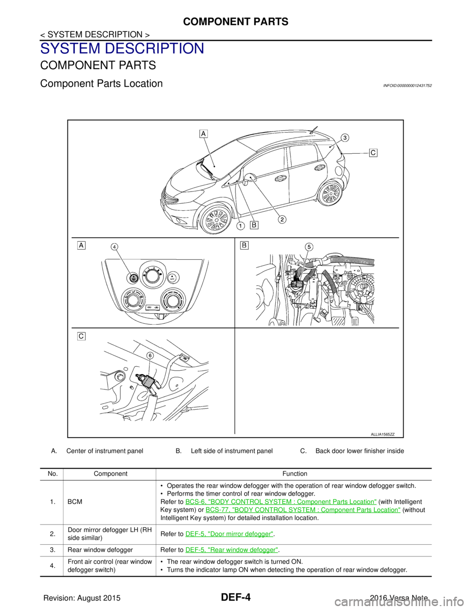
A. Center of instrument panel B. Left side of instrument panel C. Back door lower finisher inside
ALLIA1565ZZ
No.Component Function
1. BCM • Operates the rear window defogger with the operation of rear window defogger switch.
• Performs the timer control of rear window defogger.
Refer to BCS-6, "
BODY CONTROL SYSTEM : Co
mponent Parts Location" (with Intelligent
Key system) or BCS-77, "
BODY CONTROL SYSTEM : Co mponent Parts Location" (without
Intelligent Key system) for detailed installation location.
2. Door mirror defogger LH (RH
side similar)
Refer to DEF-5, "
Door mirror defogger".
3. Rear window defogger Refer to DEF-5, "
Rear window defogger".
4. Front air control (rear window
defogger switch) • The rear window defogger switch is turned ON.
• Turns the indicator lamp ON when detecting the operation of rear window defogger.
Revision: August 2015
2016 Versa Note
cardiagn.com
Page 1952 of 3641
GW-12
< REMOVAL AND INSTALLATION >
WINDSHIELD GLASS
Removal and Installation
INFOID:0000000012430531
REMOVAL
1. Remove front pillar finishers (LH/RH). Refer to INT-21, "FRONT PILLAR FINISHER : Removal and Instal-
lation".
2. Partially remove the headlining (front edge).
3. Remove cowl top cover. Refer to EXT-37, "
Removal and Installation".
4. Remove inside mirror. Refer to MIR-14, "
Removal and Installation".
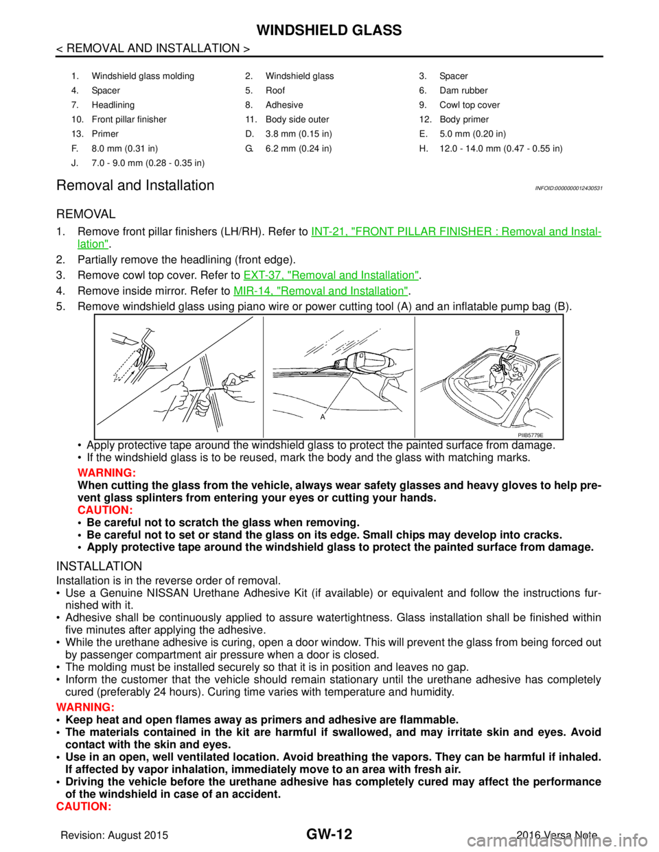
5. Remove windshield glass using piano wire or pow er cutting tool (A) and an inflatable pump bag (B).
• Apply protective tape around the windshield gla ss to protect the painted surface from damage.
• If the windshield glass is to be reused, mark the body and the glass with matching marks.
WARNING:
When cutting the glass from the vehicle, always wear safety glasses and heavy gloves to help pre-
vent glass splinters from entering your eyes or cutting your hands.
CAUTION:
• Be careful not to scratch the glass when removing.
• Be careful not to set or stand the glass on its edge. Small chips may develop into cracks.
• Apply protective tape around th e windshield glass to protect the painted surface from damage.
INSTALLATION
Installation is in the reverse order of removal.
• Use a Genuine NISSAN Urethane Adhesive Kit (if availabl e) or equivalent and follow the instructions fur-
nished with it.
• Adhesive shall be continuously applied to assure watert ightness. Glass installation shall be finished within
five minutes after applying the adhesive.
• While the urethane adhesive is curing, open a door window . This will prevent the glass from being forced out
by passenger compartment air pressure when a door is closed.
• The molding must be installed securely so that it is in position and leaves no gap.
• Inform the customer that the vehicle should remain stationary until the urethane adhesive has completely
cured (preferably 24 hours). Curing time varies with temperature and humidity.
WARNING:
• Keep heat and open flames away as primers and adhesive are flammable.
• The materials contained in the kit are harmful if swallowed, and may irritate skin and eyes. Avoid
contact with the skin and eyes.
• Use in an open, well ventilated location. Avoid breathing the vapors. They can be harmful if inhaled. If affected by vapor inhalation, imme diately move to an area with fresh air.
• Driving the vehicle before the urethane adhesive has completely cured may affect the performance
of the windshield in case of an accident.
CAUTION:
1. Windshield glass molding 2. Windshield glass 3. Spacer
4. Spacer 5. Roof 6. Dam rubber
7. Headlining 8. Adhesive 9. Cowl top cover
10. Front pillar finisher 11. Body side outer 12. Body primer
13. Primer D. 3.8 mm (0.15 in) E. 5.0 mm (0.20 in)
F. 8.0 mm (0.31 in) G. 6.2 mm (0.24 in) H. 12.0 - 14.0 mm (0.47 - 0.55 in)
J. 7.0 - 9.0 mm (0.28 - 0.35 in)
PIIB5779E
Revision: August 2015 2016 Versa Note
cardiagn.com
Page 2044 of 3641
REFRIGERANTHA-19
< PERIODIC MAINTENANCE >
C
DE
F
G H
J
K L
M A
B
HA
N
O P
4. Press UV lamp switch (5) and check A/C system for re frigerant leaks. (Where refrigerant leaks occur, flu-
orescent leak detection dye appears green in color.)
WARNING:
Do not look directly into UV lamp light source.
NOTE:
• For continuous operating time of UV lamp, fo llow the manufacturer’s operating instructions.
• Illuminate pipe joints from different angles using UV lamp to check for leaks.
• Use a mirror in areas that are di fficult to see to check for leaks.
• Refrigerant leaks from the evaporator can be detected by soaking a cotton swab or similar material with
drain hose water and illuminating it using the UV lamp.
• Dust, dirt, and packing material adhesives used for condenser, evaporator, and other components may fluoresce. Be careful not to misidentify leaks.
5. Repair or replace parts where refrigerant lea ks occur and wipe off fluorescent leak detection dye.
NOTE:
Completely wipe off fluorescent leak detection dye from gaps between parts, screw threads, and other
components using a cotton swab or similar material.
6. Use a UV lamp to check that no fluorescent leak detection dye remains after finishing work. WARNING:
Do not look directly into UV lamp light source.
NOTE:
• For continuous operating time of UV lamp, fo llow the manufacturer’s operating instructions.
• Dust, dirt, and packing material adhesives used for condenser, evaporator, and other components may
fluoresce. Be careful not to misidentify leaks.
CHECK REFRIGERANT LEAKS USING ELECTRONIC LEAK DETECTOR
WARNING:
Do not check for refrigerant leaks while the engine is running.
CAUTION:
Be careful of the following items so that in accurate checks or misidentifications are avoided.
• Do not allow refrigerant vapor, shop chemical vapors, cigarette smoke or other contaminates around the vehicle.
• Always check refrigerant leaks in a low air flow en vironment so that refrigerant may not disperse.
1. Stop the engine.
2. Connect recovery/recycling/recharging equipment or manifold gauge set to the A/C service valves.
3. Check that A/C refrigerant pressure is 345 kPa (3.52 kg/cm
2, 50 psi) or more when temperature is 16 °C
(61 °F) or more. When pressure is lower than the specified value, recycle refrigerant completely and
recharge refrigerant to the specified level.
NOTE:
Leaks may not be detected if A/C refriger ant pressure is 345 kPa (3.52 kg/cm
2, 50 psi) or less when tem-
perature is less than 16° C (61°F).
4. Clean the area where the refrigerant leak check is performed and check for refrigerant leaks along all sur- faces of pipe connections and A/C system co mponents using electronic leak detector probe.
CAUTION:
• Continue checking once leaks are found. Always co ntinue and complete checking along all pipe
connections and A/C system comp onents for additional leaks.
• When leaks are detected, clean leak ar ea using compressed air and re-check.
• When checking the evaporator for leaks, always clean inside of drain hose so that the probe sur-
face may not be exposed to water or dirt.
NOTE:
• Always check for leaks starting from the high-pressure side and continue to the low-pressure side.
• When checking the evaporator for leaks, operate blower motor for 15 minut\
es or more at the maximum speed while the engine is stopped. Insert electronic leak detector probe into drain hose and hold for 10
minutes or more.
• When disconnecting shut-off valve that is connected to A/C service valve, always evacuate remaining
refrigerant so that misidentification can be avoided.
5. Repair or replace parts where refrigerant leaks occur.
6. Start the engine and set A/C control in the following conditions. • A/C switch: ON
Revision: August 2015 2016 Versa Note
cardiagn.com
Page 2475 of 3641

MIR-1
DRIVER CONTROLS
C
DE
F
G H
I
J
K
M
SECTION MIR
A
B
MIR
N
O P
CONTENTS
MIRRORS
PRECAUTION ....... ........................................2
PRECAUTIONS .............................................. .....2
Precaution for Supplemental Restraint System
(SRS) "AIR BAG" and "SEAT BELT PRE-TEN-
SIONER" ............................................................. ......
2
Precaution for Work ..................................................2
PREPARATION ............................................3
PREPARATION .............................................. .....3
Special Service Tools .......................................... ......3
Commercial Service Tools .......................................3
WIRING DIAGRAM .......................................4
DOOR MIRROR SYSTEM .............................. .....4
OUTSIDE MIRROR ................................................ ......4
OUTSIDE MIRROR : Wiring Diagram .......................4
DTC/CIRCUIT DIAGNOSIS ..........................7
DOOR MIRROR SYSTEM .............................. .....7
Component Inspection ........................................ ......7
SYMPTOM DIAGNOSIS ...............................8
SQUEAK AND RATTLE TROUBLE DIAG-
NOSES ...............................................................
8
Work Flow ............................................................ .....8
Generic Squeak and Rattle Troubleshooting ............9
Diagnostic Worksheet ..............................................12
REMOVAL AND INSTALLATION ...............14
INSIDE MIRROR ...............................................14
Exploded View ..................................................... ....14
Removal and Installation .........................................14
DOOR MIRROR ................................................15
Exploded View .........................................................15
Removal and Installation .........................................15
DOOR MIRROR GLASS ...................................17
Removal and Installation .........................................17
DOOR MIRROR REAR FINISHER ...................18
Removal and Installation .........................................18
DOOR MIRROR REMOTE CONTROL
SWITCH .............................................................
19
Removal and Installation .........................................19
Revision: August 2015 2016 Versa Note
cardiagn.com
Page 2488 of 3641
MIR-14
< REMOVAL AND INSTALLATION >
INSIDE MIRROR
REMOVAL AND INSTALLATION
INSIDE MIRROR
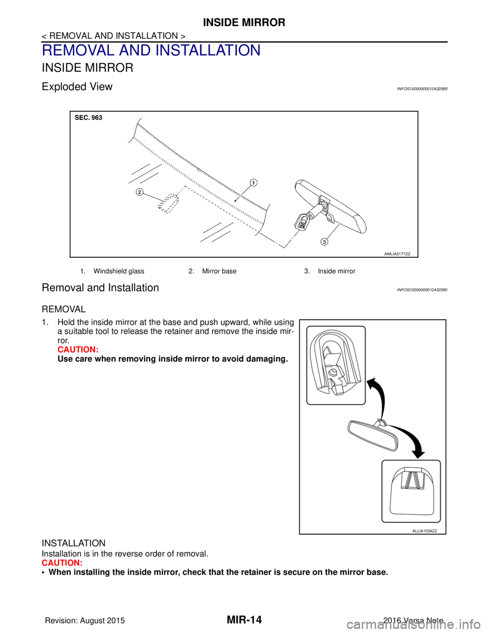
Exploded ViewINFOID:0000000012432089
Removal and InstallationINFOID:0000000012432090
REMOVAL
1. Hold the inside mirror at the base and push upward, while usinga suitable tool to release the retainer and remove the inside mir-
ror.
CAUTION:
Use care when removing inside mirror to avoid damaging.
INSTALLATION
Installation is in the reverse order of removal.
CAUTION:
• When installing the inside mi rror, check that the retainer is secure on the mirror base.
1. Windshield glass 2. Mirror base 3. Inside mirror
AWLIA2177ZZ
ALLIA1034ZZ
Revision: August 2015 2016 Versa Note
cardiagn.com
Page 2489 of 3641
DOOR MIRRORMIR-15
< REMOVAL AND INSTALLATION >
C
DE
F
G H
I
J
K
M A
B
MIR
N
O P
DOOR MIRROR
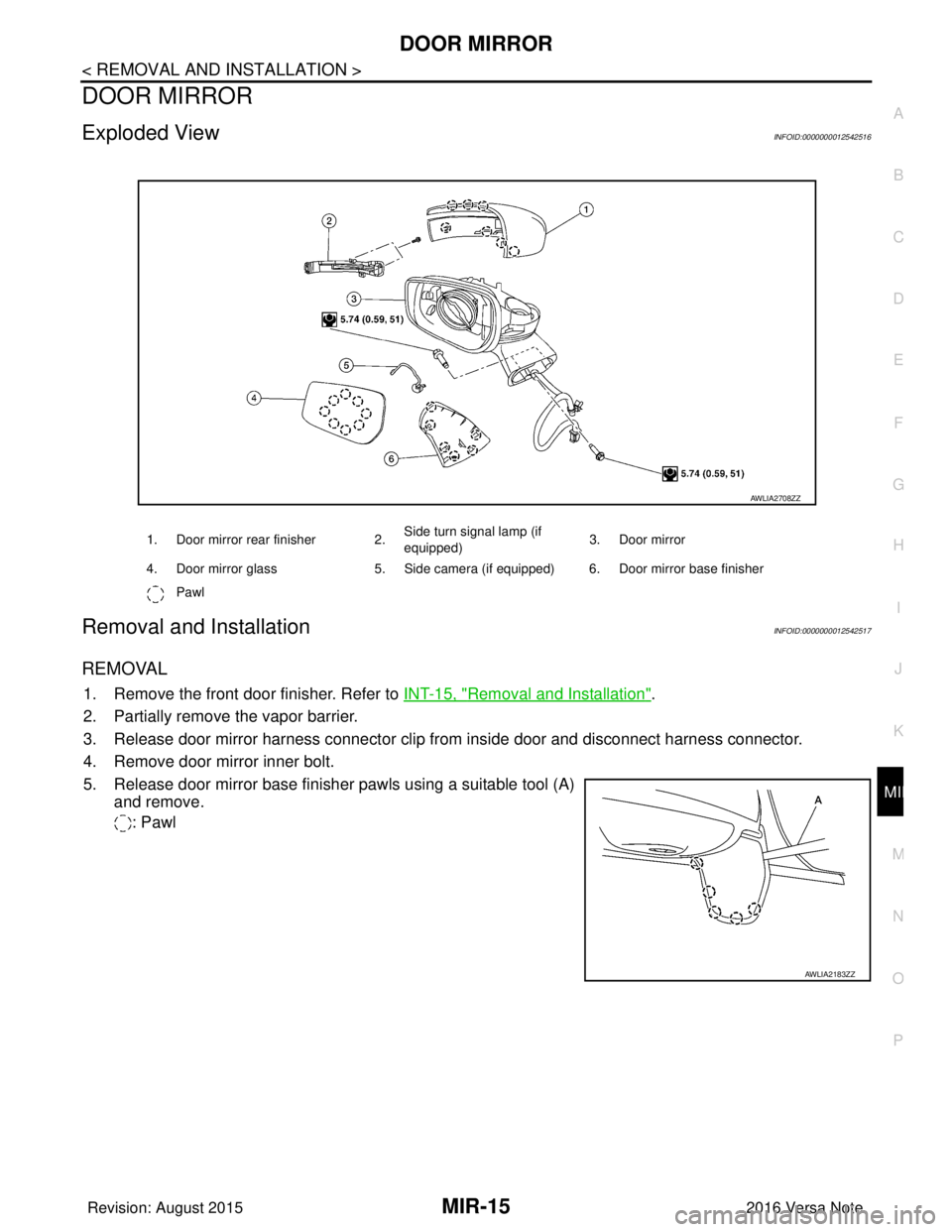
Exploded ViewINFOID:0000000012542516
Removal and InstallationINFOID:0000000012542517
REMOVAL
1. Remove the front door finisher. Refer to INT-15, "Removal and Installation".
2. Partially remove the vapor barrier.
3. Release door mirror harness connector clip from inside door and disconnect harness connector.
4. Remove door mirror inner bolt.
5. Release door mirror base finisher pawls using a suitable tool (A) and remove.
: Pawl
1. Door mirror rear finisher 2. Side turn signal lamp (if
equipped)
3. Door mirror
4. Door mirror glass 5. Side camera (if equipped) 6. Door mirror base finisher
Pawl
AWLIA2708ZZ
AWLIA2183ZZ
Revision: August 2015 2016 Versa Note
cardiagn.com
Page 2631 of 3641

PG-44
< WIRING DIAGRAM >
HARNESS
C2 M6 W/4 : Dongle unitB1 M61 — : Body ground
B2 M7 W/16 : Door mirror remote control switch C1 M62 W/2 : Front blower motor
D1 M8 G/20 : Joint connector–M02 C3 M64 W/8 : Steering angle sensor
A3 M9 W/12 : To D1 E3 M65 W/4 : Front air control
D3 M10 L/20 : Joint connector–M01 D5 M66 B/3 : Console power socket
B4 M11 W/2 : To B28 A4 M69 SMJ : To E7
F3 M12 W/16 : To B29 E2 M70 W/20 : AV control unit
F3 M13 W/24 : To B30 D3 M71 W/24 : AV control unit
B3 M14 BR/6 : Rear window defogger relay F2 M75 Y/4 : To D101
B4 M15 W/16 : To B23 D2 M76 GR/5 : AV control unit
A4 M16 W/24 : To B24 E1 M77 Y/4 : Front passenger air bag module
D5 M17 B/1 : Parking brake switch A4 M78 B/2 :To E11
A2 M18 W/40 : BCM (Body contro
l module) (Without
Intelligent Key system) F1 M79 — : Body ground
A1 M19 W/15 : BCM (Body contro
l module) (Without
Intelligent Key system) A 3 M 8 0 Y / 4 : T o D 3
A2 M20 B/15 : BCM (Body contro
l module) (Without
Intelligent Key system) F2 M81 W/12 : To D115
C2 M21 W/4 : NATS antenna amp. C1 M82 W/40 : Combination meter (With type A)
B3 M22 W/16 : Data link connector D5 M83 B/3 : G sensor
E 4 M 2 3 W / 4 : Remote keyless entry receiver (Without
Intelligent Key system) E2 M84 — : Body ground
C1 M24 W/40 : Combination meter (With type B) E2 M85 — : Body ground
C4 M25 W/8 : Push–button ignition swtich F5 M89 L/2 : Inside key antenna (Console)
C3 M26 W/6 : Ignition switch E1 M90 B/4: Remote keyless entry receiver (With
Intelligent Key system without tire pressure
monitoring system)
C2 M27 BR/2 : Key switch F2 M92 W/12 : To D116
C3 M28 W/16 : Combination switch A3 M93 W/24 : To D16
E 3 M 2 9 W / 2 4 : T o B 1 F 1 M 9 4 W / 4: Remote keyless entry receiver (With
Intelligent Key system with tire pressure
monitoring system)
C4 M30 GR/8 : Combination switch (Spiral cable) D3 M95 L/2 : Inside key antenna (Instrument center)
C3 M31 Y/6 : Combination switch (Spiral cable) A2 M97 B/40 : BCM (Body contro
l module) (With
Intelligent Key system)
E5 M32 W/16 : To M201 A2 M98 W/40: BCM (Body contro
l module) (With
Intelligent Key system)
E3 M33 B/15 : Front air control A2 M99 W/15: BCM (Body contro
l module) (With
Intelligent Key system)
B3 M34 GR/6 : VDC off switch A2 M100 B / 1 5: BCM (Body contro
l module) (With
Intelligent Key system)
D4 M35 Y/28 : Air bag diagnosis sensor unit D2 M101 W/16 : Audio unit (With base audio system)
D1 M36 BR/2 : Front passenger air bag off indicator A3 M103 W/12 : Accessory prewire LH
E4 M38 W/8 : CVT shift selector E2 M104 W/12 : Accessory prewire RH
B3 M39 L/4 : Accessory relay–2 C2 M151 BR/4 : Front blower motor resistor
E2 M40 W/32 : Audio unit (With display audio system) Console sub harness
B3 M41 B/5 : Back door lock actuator relay E5 M201 W / 1 6 : T o M 3 2
C3 M42 BR/4 : Thermo control amp. E4 M202 B/3 : Console power socket
E2 M43 W/20 : Audio unit (With base audio system) C4 M203 BR/6 : Heated seat swtich RH
Revision: August 2015 2016 Versa Note
cardiagn.com