2016 NISSAN NOTE wheel alignment
[x] Cancel search: wheel alignmentPage 2743 of 3641
SERVICE DATA AND SPECIFICATIONS (SDS)RSU-15
< SERVICE DATA AND SPECIFICATIONS (SDS)
C
DF
G H
I
J
K L
M A
B
RSU
N
O P
SERVICE DATA AND SPECIFICATIONS (SDS)
SERVICE DATA AND SPECIFICATIONS (SDS)
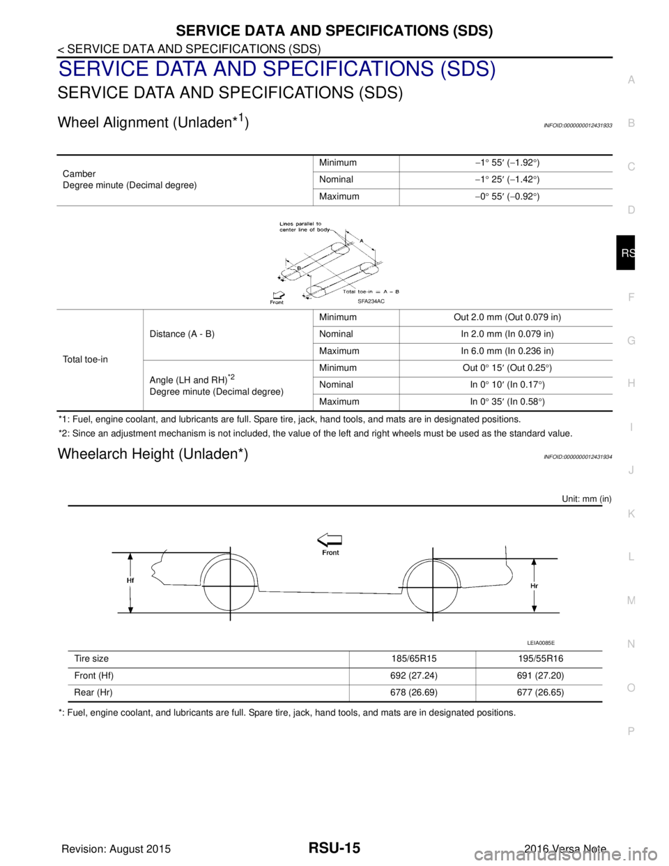
Wheel Alignment (Unladen*1)INFOID:0000000012431933
*1: Fuel, engine coolant, and lubricants are full. Spare tire, jack, hand tools, and mats are in designated positions.
*2: Since an adjustment mechanism is not included, the value of the left and right wheels must be used as the standard value.
Wheelarch Height (Unladen*)INFOID:0000000012431934
Unit: mm (in)
*: Fuel, engine coolant, and lubricants are full. Spare tire, jack, hand tools, and mats are in designated positions. Camber
Degree minute (Decimal degree)
Minimum
−1° 55 ′ ( −1.92 °)
Nominal −1° 25 ′ ( −1.42 °)
Maximum −0° 55 ′ ( −0.92 °)
Total toe-in Distance (A - B)
Minimum
Out 2.0 mm (Out 0.079 in)
Nominal In 2.0 mm (In 0.079 in)
Maximum In 6.0 mm (In 0.236 in)
Angle (LH and RH)
*2
Degree minute (Decimal degree) Minimum Out 0
° 15 ′ (Out 0.25 °)
Nominal In 0° 10 ′ (In 0.17 °)
Maximum In 0° 35 ′ (In 0.58 °)
SFA234AC
Tire size 185/65R15195/55R16
Front (Hf) 692 (27.24)691 (27.20)
Rear (Hr) 678 (26.69)677 (26.65)
LEIA0085E
Revision: August 2015 2016 Versa Note
cardiagn.com
Page 3121 of 3641
COLLISION DIAGNOSISSR-5
< BASIC INSPECTION >
C
DE
F
G
I
J
K L
M A
B
SR
N
O P
BASIC INSPECTION
COLLISION DIAGNOSIS
For Frontal CollisionINFOID:0000000012430564
FOR FRONTAL COLLISION: When SRS is activated in a collision
CAUTION:
Due to varying models and option levels, not all parts listed in the chart below apply to all vehicles.
WORK PROCEDURE
1. Before performing any of the following steps, ensur e that all vehicle body and structural repairs have been
completed.
2. Replace the diagnosis sensor unit.
3. Remove the front air bag modules, crash zone sens or assembly, bracket and seat belt pre-tensioner
assemblies.
4. Check the SRS components using the table below:
Replace any SRS components showing visible signs of damage. (dents, cracks and deformation, etc.)
5. Install new front air bag modules, crash zone sens or assembly, bracket and seat belt pre-tensioner
assemblies.
6. Perform self-diagnosis using CONSULT or air bag warning lamp. Refer to SRC-14, "
Description" for
details.
Ensure entire SRS operates properly.
7. After the work is completed, perform self-diagnosis to check that no malfunction is detected. Refer to
SRC-14, "
Description".
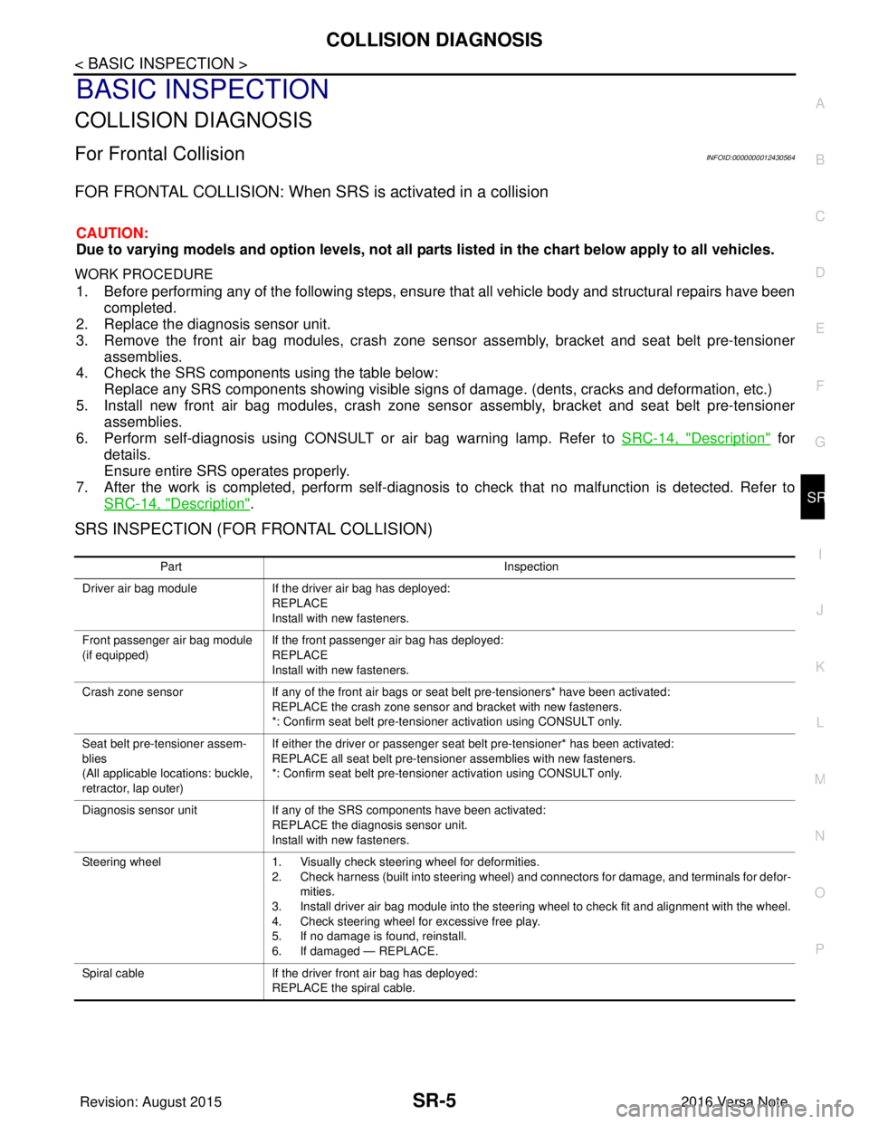
SRS INSPECTION (FOR FRONTAL COLLISION)
Part Inspection
Driver air bag module If the driver air bag has deployed:
REPLACE
Install with new fasteners.
Front passenger air bag module
(if equipped) If the front passenger air bag has deployed:
REPLACE
Install with new fasteners.
Crash zone sensor If any of the front air bags or seat belt pre-tensioners* have been activated:
REPLACE the crash zone sensor and bracket with new fasteners.
*: Confirm seat belt pre-tensioner activation using CONSULT only.
Seat belt pre-tensioner assem-
blies
(All applicable locations: buckle,
retractor, lap outer) If either the driver or passenger seat belt pre-tensioner* has been activated:
REPLACE all seat belt pre-tensioner assemblies with new fasteners.
*: Confirm seat belt pre-tensioner activation using CONSULT only.
Diagnosis sensor unit If any of the SRS components have been activated:
REPLACE the diagnosis sensor unit.
Install with new fasteners.
Steering wheel 1. Visually check steering wheel for deformities.
2. Check harness (built into steering wheel) and connectors for damage, and terminals for defor-
mities.
3. Install driver air bag module into the steering wheel to check fit and alignment with the wheel.
4. Check steering wheel for excessive free play.
5. If no damage is found, reinstall.
6. If damaged — REPLACE.
Spiral cable If the driver front air bag has deployed:
REPLACE the spiral cable.
Revision: August 2015 2016 Versa Note
cardiagn.com
Page 3122 of 3641

SR-6
< BASIC INSPECTION >
COLLISION DIAGNOSIS
FOR FRONTAL COLLISION: When SRS is not activated in a collision
CAUTION:
Due to varying models and option levels, not all parts listed in the chart below apply to all vehicles.
WORK PROCEDURE
1. Before performing any of the following steps, ensure that all vehicle body and structural repairs have been
completed.
2. Check the SRS components using the table below: Replace any SRS components showing visible signs of damage. (dents, cracks and deformation, etc.)
3. Perform self-diagnosis using CONSULT or air bag warning lamp. Refer to SRC-14, "
Description" for
details.
Ensure entire SRS operates properly.
4. After the work is completed, perform self-diagnosis to check that no malfunction is detected. Refer to
SRC-14, "
Description".
SRS INSPECTION (FOR FRONTAL COLLISION)
Occupant classification system
(Passenger seat) 1. Remove passenger seat assembly.
2. Check control unit case for dents, cracks of deformities.
3. Check connectors for damage and terminals for deformities.
4. Check seat frame and cushion pan for dents or deformities.
5. If no damage is found, reinstall seat with new fasteners.
6. If damaged — REPLACE seat cushion assembly with new fasteners.
7. Perform zero point reset function after front passenger seat is installed in the vehicle and all
bolts are tightened to specification. Refer to SRC-39, "
ZERO POINT RESET : Special Repair
Requirement".
Harness and connectors 1. Check connectors for poor connection, damage, and terminals for deformities. 2. Check harness for binding, chafing, cuts, or deformities.
3. If no damage is found, reinstall the harness and connectors.
4. If damaged — REPLACE the damaged harness. Do not attempt to repair, splice or modify any SRS harness.
Instrument panel assembly If the passenger front air bag has deployed: REPLACE the instrument panel assembly. (integrated type)
Part
Inspection
Part Inspection
Driver air bag module If the driver air bag has NOT been activated:
1. Remove driver air bag module. Check harness cover and connectors for damage, terminals for deformities, and harness for binding.
2. Install driver air bag module into the steering wheel to check fit and alignment with the wheel.
3. If no damage is found, reinstall with new fasteners.
4. If damaged — REPLACE. Install driver air bag modules with new fasteners.
Front passenger air bag module
(if equipped) If the front passenger air bag has NOT been activated:
1. Remove front passenger air bag module. Check harness cover and connectors for damage,
terminals for deformities, and harness for binding.
2. Install front passenger air bag module into the instrument panel to check fit with the instrument panel.
3. If no damage is found, reinstall with new fasteners.
4. If damaged — REPLACE. Install front passenger air bag modules with new fasteners.
Crash zone sensor If the front air bags or seat belt pre-tensioners have NOT been activated:
1. Remove the crash zone sensor. Check harness connectors for damage, terminals for defor-
mities, and harness for binding.
2. Check for visible signs of damage (dents, cracks, deformation) of the crash zone sensor and bracket.
3. Install the crash zone sensor to check fit.
4. If no damage is found, reinstall with new fasteners.
5. If damaged — REPLACE the crash zone sensor and bracket with new fasteners.
Revision: August 2015 2016 Versa Note
cardiagn.com
Page 3123 of 3641
COLLISION DIAGNOSISSR-7
< BASIC INSPECTION >
C
DE
F
G
I
J
K L
M A
B
SR
N
O P
For Side and Rollover CollisionINFOID:0000000012430565
FOR SIDE AND ROLLOVER COLLISION: When SRS is activated in a collision
CAUTION:
Due to varying models and option levels, not all parts listed in the chart below apply to all vehicles.
WORK PROCEDURE
1. Before performing any of the following steps, ensur e that all vehicle body and structural repairs have been
completed.
2. Replace the following components:
- Front seat back assembly (on the side on which side air bag is activated).
- Door finisher (on the side on which door-mounted curtain air bag is activated).
- Pop-up roll bar assemblies and pop-up roll bar covers.
- Side air bag (satellite) sensor LH/RH (on the side on which side air bag is activated).
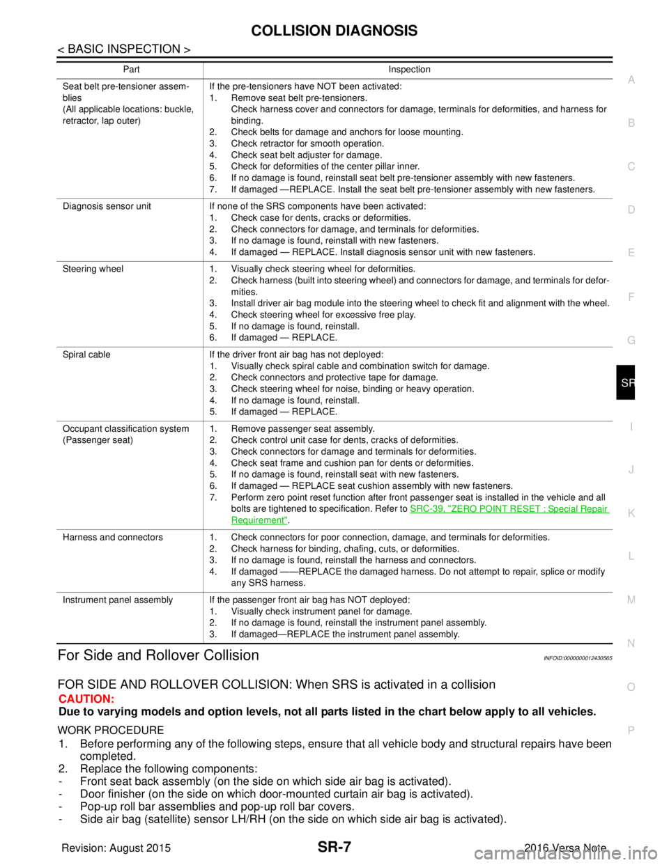
Seat belt pre-tensioner assem-
blies
(All applicable locations: buckle,
retractor, lap outer)If the pre-tensioners have NOT been activated:
1. Remove seat belt pre-tensioners.
Check harness cover and connectors for damage, terminals for deformities, and harness for
binding.
2. Check belts for damage and anchors for loose mounting.
3. Check retractor for smooth operation.
4. Check seat belt adjuster for damage.
5. Check for deformities of the center pillar inner.
6. If no damage is found, reinstall seat belt pre-tensioner assembly with new fasteners.
7. If damaged —REPLACE. Install the seat belt pre-tensioner assembly with new fasteners.
Diagnosis sensor unit If none of the SRS components have been activated:
1. Check case for dents, cracks or deformities.
2. Check connectors for damage, and terminals for deformities.
3. If no damage is found, reinstall with new fasteners.
4. If damaged — REPLACE. Install diagnosis sensor unit with new fasteners.
Steering wheel 1. Visually check steering wheel for deformities.
2. Check harness (built into steering wheel) and connectors for damage, and terminals for defor-
mities.
3. Install driver air bag module into the steering wheel to check fit and alignment with the wheel.
4. Check steering wheel for excessive free play.
5. If no damage is found, reinstall.
6. If damaged — REPLACE.
Spiral cable If the driver front air bag has not deployed:
1. Visually check spiral cable and combination switch for damage.
2. Check connectors and protective tape for damage.
3. Check steering wheel for noise, binding or heavy operation.
4. If no damage is found, reinstall.
5. If damaged — REPLACE.
Occupant classification system
(Passenger seat) 1. Remove passenger seat assembly.
2. Check control unit case for dents, cracks of deformities.
3. Check connectors for damage and terminals for deformities.
4. Check seat frame and cushion pan for dents or deformities.
5. If no damage is found, reinstall seat with new fasteners.
6. If damaged — REPLACE seat cushion assembly with new fasteners.
7. Perform zero point reset function after front passenger seat is installed in the vehicle and all
bolts are tightened to specification. Refer to SRC-39, "
ZERO POINT RESET : Special Repair
Requirement".
Harness and connectors 1. Check connectors for poor connection, damage, and terminals for deformities.
2. Check harness for binding, chafing, cuts, or deformities.
3. If no damage is found, reinstall the harness and connectors.
4. If damaged ——REPLACE the damaged harness. Do not attempt to repair, splice or modify
any SRS harness.
Instrument panel assembly If the passenger front air bag has NOT deployed: 1. Visually check instrument panel for damage.
2. If no damage is found, reinstall the instrument panel assembly.
3. If damaged—REPLACE the instrument panel assembly.
Part
Inspection
Revision: August 2015 2016 Versa Note
cardiagn.com
Page 3187 of 3641

PRECAUTIONSSTC-3
< PRECAUTION >
C
DE
F
H I
J
K L
M A
B
STC
N
O P
PRECAUTION
PRECAUTIONS
Precaution for Supplemental Restraint System (SRS) "AIR BAG" and "SEAT BELT
PRE-TENSIONER"
INFOID:0000000012431939
The Supplemental Restraint System such as “AIR BAG” and “SEAT BELT PRE-TENSIONER”, used along
with a front seat belt, helps to reduce the risk or severi ty of injury to the driver and front passenger for certain
types of collision. Information necessary to service the system safely is included in the SR and SB section of
this Service Manual.
WARNING:
• To avoid rendering the SRS inoper ative, which could increase the risk of personal injury or death in
the event of a collision which would result in air bag inflation, all maintenance must be performed by
an authorized NISSAN/INFINITI dealer.
• Improper maintenance, including in correct removal and installation of the SRS, can lead to personal
injury caused by unintentional act ivation of the system. For removal of Spiral Cable and Air Bag
Module, see the SR section.
• Do not use electrical test equipm ent on any circuit related to the SRS unless instructed to in this
Service Manual. SRS wiring harnesses can be identi fied by yellow and/or orange harnesses or har-
ness connectors.
PRECAUTIONS WHEN USING POWER TOOLS (AIR OR ELECTRIC) AND HAMMERS
WARNING:
• When working near the Airbag Diagnosis Sensor Un it or other Airbag System sensors with the Igni-
tion ON or engine running, DO NOT use air or el ectric power tools or strike near the sensor(s) with a
hammer. Heavy vibration could activate the sensor( s) and deploy the air bag(s), possibly causing
serious injury.
• When using air or electric power tools or hammers, always switch the Ignition OFF, disconnect the
battery and wait at least three mi nutes before performing any service.
Service Notice and Precautions for EPS SystemINFOID:0000000012431940
• Check the following item when performing the trouble diagnosis:
- Check for possible causes of the malfunction by inte rviewing the customer as to what conditions were
present when the symptom occurred.
- Check if the steering wheel and the EPS control unit are genuine parts.
- Check if the air pressure and size of each tire is correct.
- Check if the installation of the links and suspension components are correct.
- Check if the tires are worn evenly, indicating the wheel alignment is correct.
- Check if the installation of the steering column and t he steering gear are correct. Check for loose bolts, dam-
aged links, cracked boots and leaking grease, etc.
- Check for damage or modification to suspension or body resulting in increased weight or altered ground clearance.
- Check if the battery voltage is proper.
- Check the EPS control unit harness to be sure the harness connectors are fully seated.
• Before connecting or disconnecting the EPS control uni t harness connector, turn ignition switch “OFF” and
disconnect the battery cable from the negative terminal. Battery voltage is applied to the EPS control unit
even if ignition switch is turned “OFF”.
Revision: August 2015 2016 Versa Note
cardiagn.com
Page 3218 of 3641
STC-34
< SYMPTOM DIAGNOSIS >
UNBALANCE STEERING WHEEL TURNING FORCE AND RETURN BETWEEN RIGHT AND LEFT
UNBALANCE STEERING WHEEL TU RNING FORCE AND RETURN BE-
TWEEN RIGHT AND LEFT
DescriptionINFOID:0000000012431979
Unbalance steering wheel turning force and return between right and left.
Diagnosis ProcedureINFOID:0000000012431980
1.CHECK THE ILLUMINATION OF THE EPS WARNING LAMP
Check the EPS warning lamp while engine is running.
Does the EPS warning lamp turn OFF?
YES >> GO TO 2.
NO >> Refer to STC-29, "
Diagnosis Procedure".
2.CHECK WHEEL ALIGNMENT
1. Check the wheel alignment. Refer to FSU-7, "
Inspection".
2. Perform “Self Diagnostic Result” of “EPS”.
Is the inspection result normal?
YES >> GO TO 3.
NO >> Adjustment of wheel alignment. Refer to FSU-8, "
Adjustment".
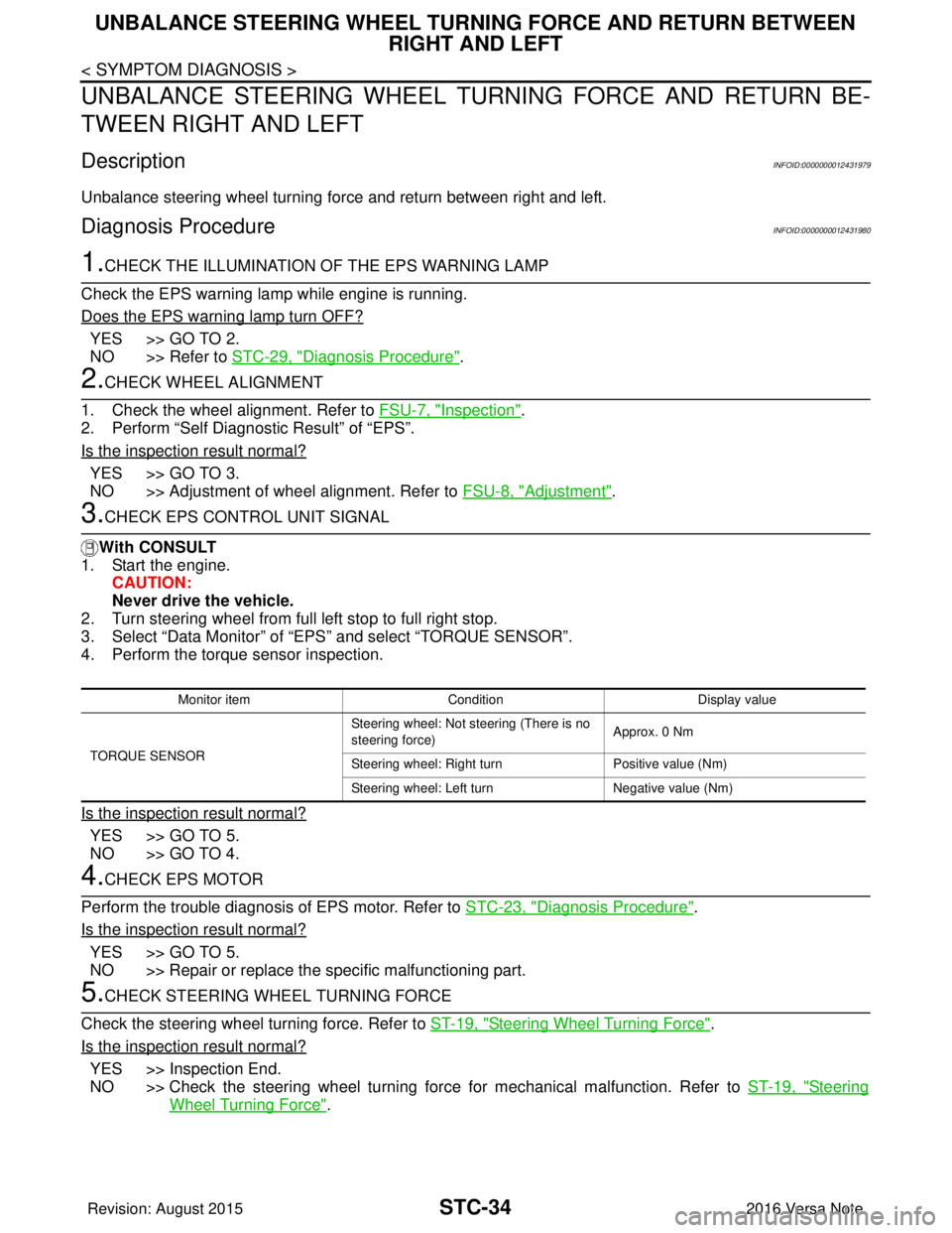
3.CHECK EPS CONTROL UNIT SIGNAL
With CONSULT
1. Start the engine.
CAUTION:
Never drive the vehicle.
2. Turn steering wheel from full left stop to full right stop.
3. Select “Data Monitor” of “EPS” and select “TORQUE SENSOR”.
4. Perform the torque sensor inspection.
Is the inspection result normal?
YES >> GO TO 5.
NO >> GO TO 4.
4.CHECK EPS MOTOR
Perform the trouble diagnosis of EPS motor. Refer to STC-23, "
Diagnosis Procedure".
Is the inspection result normal?
YES >> GO TO 5.
NO >> Repair or replace the specific malfunctioning part.
5.CHECK STEERING WHEEL TURNING FORCE
Check the steering wheel turning force. Refer to ST-19, "
Steering Wheel Turning Force".
Is the inspection result normal?
YES >> Inspection End.
NO >> Check the steering wheel turning force for mechanical malfunction. Refer to ST-19, "
Steering
Wheel Turning Force".
Monitor item ConditionDisplay value
TORQUE SENSOR Steering wheel: Not st
eering (There is no
steering force) Approx. 0 Nm
Steering wheel: Right turn Positive value (Nm)
Steering wheel: Left turn Negative value (Nm)
Revision: August 2015 2016 Versa Note
cardiagn.com
Page 3223 of 3641

ST-2
< PRECAUTION >
PRECAUTIONS
PRECAUTION
PRECAUTIONS
Precaution for Supplemental Restraint System (SRS) "AIR BAG" and "SEAT BELT
PRE-TENSIONER"
INFOID:0000000012430493
The Supplemental Restraint System such as “A IR BAG” and “SEAT BELT PRE-TENSIONER”, used along
with a front seat belt, helps to reduce the risk or severity of injury to the driver and front passenger for certain
types of collision. Information necessary to service the system safely is included in the SR and SB section of
this Service Manual.
WARNING:
• To avoid rendering the SRS inopera tive, which could increase the risk of personal injury or death in
the event of a collision which would result in air bag inflation, all maintenance must be performed by
an authorized NISSAN/INFINITI dealer.
• Improper maintenance, including in correct removal and installation of the SRS, can lead to personal
injury caused by unintent ional activation of the system. For re moval of Spiral Cable and Air Bag
Module, see the SR section.
• Do not use electrical test equipmen t on any circuit related to the SRS unless instructed to in this
Service Manual. SRS wiring harn esses can be identified by yellow and/or orange harnesses or har-
ness connectors.
PRECAUTIONS WHEN USING POWER TOOLS (AIR OR ELECTRIC) AND HAMMERS
WARNING:
• When working near the Airbag Diagnosis Sensor Unit or other Airbag System sensors with the Igni-
tion ON or engine running, DO NOT use air or electri c power tools or strike near the sensor(s) with a
hammer. Heavy vibration could activate the sensor( s) and deploy the air bag(s), possibly causing
serious injury.
• When using air or electric power tools or hammers , always switch the Ignition OFF, disconnect the
battery and wait at least three minutes before performing any service.
Service Notice or Precautions for Steering SystemINFOID:0000000012430494
• In case of removing the steering gear, make the final tightening with grounded and unloaded vehicle condi- tion, and then check wheel alignment.
• Observe the following precautions when disassembling.
- Before disassembly, thoroughly clean the outside of the unit.
- Disassembly should be done in a clean work area. It is im portant to prevent the internal parts from becoming
contaminated by dirt or other foreign matter.
- For easier and proper assembly, place disassembled parts in order on a parts rack.
- Use nylon cloth or paper towels to clean the parts; co mmon shop rags can leave lint that might interfere with
their operation.
- Do not reuse non-reusable parts.
- Before assembling, apply the specified grease to the directed parts.
FOR ELECTRIC POWER STEERING (EPS)
• During quick steering, rasping noise may be heard from around the steering wheel. This is not a malfunction.
The noise is an operating noise of the EPS system under normal conditions. If the rasping noise occurs dur-
ing slow steering, this may not be an operating noise of the system. In this case, it is necessary to find out
the location of the noise and repair, if necessary.
• Do not repeat static steering. (Mot or and EPS control unit could be heated.)
Revision: August 2015 2016 Versa Note
cardiagn.com
Page 3226 of 3641
STEERING WHEELST-5
< BASIC INSPECTION >
C
DE
F
H I
J
K L
M A
B
ST
N
O P
BASIC INSPECTION
STEERING WHEEL
InspectionINFOID:0000000012430497
CONDITION OF INSTALLATION
• Check installation conditions of steering gear, front suspension, axle and steering column.
• Check if movement exists when steering wheel is mo ved up and down, to the left and right and to the axial
direction.
• Verify that the steering gear nuts are tightened to specification. Refer to ST-14, "
Exploded View".
STEERING WHEEL PLAY
1. Set the front wheels and tires in the straight-ahead position, start engine, then lightly turn steering wheel
to the left and right until the front wheels start to move. Measure steering wheel movement on the outer
circumference.
2. When the measurement value is outside the standard va lue, check backlash for each joint of steering col-
umn and installation condition of steering gear.
STEERING WHEEL NEUTRAL POSITION
Check steering wheel neutral position using the following procedure:
1. Confirm that front wheel alignment is correct. Refer to FSU-8, "
Adjustment".
2. Set the front wheels and tires in the straight-ahead posit ion, check if steering wheel is in the neutral posi-
tion.
3. If it is not in the neutral position, remo ve steering wheel and reinstall it correctly.
4. If the neutral position cannot be attained by repositi oning the steering wheel two teeth or less on steering
stem, loosen the steering gear outer socket lock nuts, then adjust the inner sockets by the same amount
in the opposite direction.
5. Re-check the front wheel alignment. Refer to FSU-8, "
Adjustment".
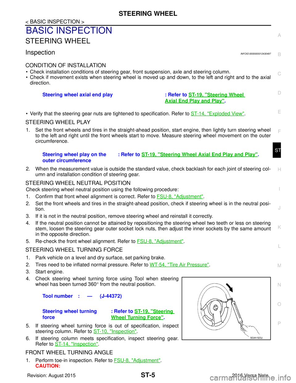
STEERING WHEEL TURNING FORCE
1. Park vehicle on a level and dry surface, set parking brake.
2. Tires need to be inflated normal pressure. Refer to WT-54, "
Tire Air Pressure".
3. Start engine.
4. Check steering wheel turning force using Tool when steering wheel has been turned 360 ° from the neutral position.
5. If steering wheel turning force is out of specification, inspect steering column. Refer to ST-10, "
Inspection".
6. If steering column meets specification, inspect steering gear. Refer to ST-14, "
Inspection".
FRONT WHEEL TURNING ANGLE
1. Perform toe-in inspection. Refer to FSU-8, "Adjustment".
CAUTION: Steering wheel axial end play : Refer to
ST-19, "
Steering Wheel
Axial End Play and Play".
Steering wheel play on the
outer circumference : Refer to
ST-19, "
Steering Wheel Axia l End Play and Play".
Tool number : — (J-44372)
Steering wheel turning
force : Refer to
ST-19, "
Steering
Wheel Turning Force".
SGIA1523J
Revision: August 2015 2016 Versa Note
cardiagn.com