2016 NISSAN NOTE steering wheel
[x] Cancel search: steering wheelPage 2085 of 3641

STEERING COLUMN COVERSIP-17
< REMOVAL AND INSTALLATION >
C
DE
F
G H
I
K L
M A
B
IP
N
O P
STEERING COLUMN COVERS
Removal and InstallationINFOID:0000000012430779
REMOVAL
1. Remove instrument lower panel LH. Refer to IP-24, "Removal and Installation".
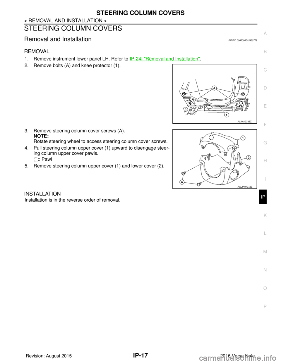
2. Remove bolts (A) and knee protector (1).
3. Remove steering column cover screws (A). NOTE:
Rotate steering wheel to access steering column cover screws.
4. Pull steering column upper cover (1) upward to disengage steer- ing column upper cover pawls.
: Pawl
5. Remove steering column upper cover (1) and lower cover (2).
INSTALLATION
Installation is in the reverse order of removal.
ALJIA1233ZZ
AWJIA0707ZZ
Revision: August 2015 2016 Versa Note
cardiagn.com
Page 2320 of 3641

GENERAL MAINTENANCEMA-5
< PERIODIC MAINTENANCE >
C
DE
F
G H
I
J
K L
M B
MA
N
O A
PERIODIC MAINTENANCE
GENERAL MAINTENANCE
Explanation of Gene
ral MaintenanceINFOID:0000000012432243
General maintenance includes those items which shoul d be checked during the normal day-to-day operation
of the vehicle. They are essential if the vehicle is to continue operati ng properly. The owners can perform the
checks and inspections themselves or they can have their NISSAN dealers do them.
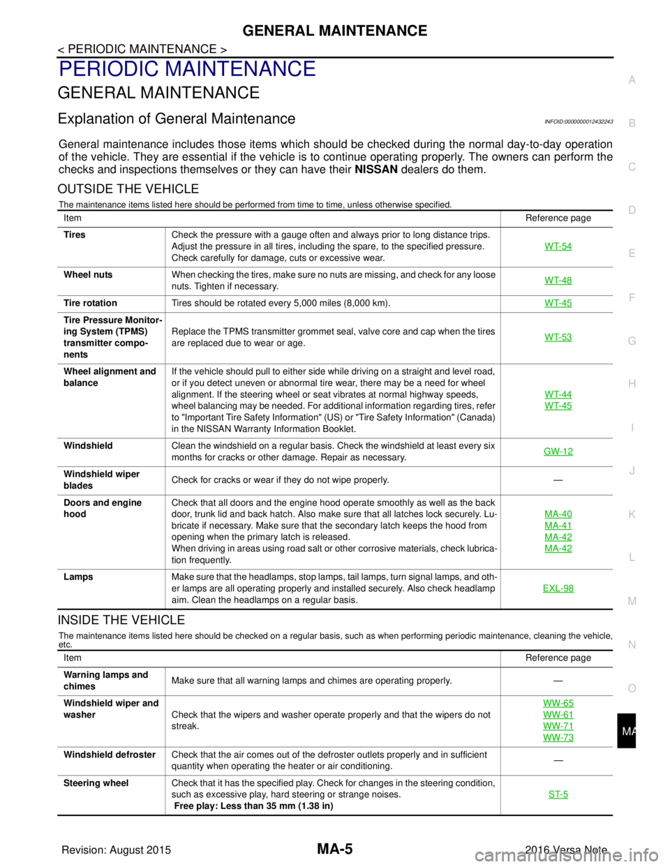
OUTSIDE THE VEHICLE
The maintenance items listed here should be performed from time to time, unless otherwise specified.
INSIDE THE VEHICLE
The maintenance items listed here should be checked on a regular basis, such as when performing periodic maintenance, cleaning the vehicle,
etc.
Item Reference page
Tires Check the pressure with a gauge often and always prior to long distance trips.
Adjust the pressure in all tires, including the spare, to the specified pressure.
Check carefully for damage, cuts or excessive wear. WT-54
Wheel nuts
When checking the tires, make sure no nuts are missing, and check for any loose
nuts. Tighten if necessary. WT-48
Tire rotation
Tires should be rotated every 5,000 miles (8,000 km). WT-45
Tire Pressure Monitor-
ing System (TPMS)
transmitter compo-
nentsReplace the TPMS transmitter grommet seal, valve core and cap when the tires
are replaced due to wear or age.
WT-53
Wheel alignment and
balanceIf the vehicle should pull to either side while driving on a straight and level road,
or if you detect uneven or abnormal tire wear, there may be a need for wheel
alignment. If the steering wheel or seat vibrates at normal highway speeds,
wheel balancing may be needed. For additional information regarding tires, refer
to "Important Tire Safety Information" (US) or "Tire Safety Information" (Canada)
in the NISSAN Warranty
Information Booklet. WT-44
WT-45
Windshield
Clean the windshield on a regular basis. Check the windshield at least every six
months for cracks or other damage. Repair as necessary. GW-12
Windshield wiper
bladesCheck for cracks or wear if they do not wipe properly.
—
Doors and engine
hood Check that all doors and the engine hood operate smoothly as well as the back
door, trunk lid and back hatch. Also make sure that all latches lock securely. Lu-
bricate if necessary. Make sure that the secondary latch keeps the hood from
opening when the primary latch is released.
When driving in areas using road salt or other corrosive materials, check lubrica-
tion frequently. MA-40
MA-41
MA-42
MA-42
Lamps
Make sure that the headlamps, stop lamps, tail lamps, turn signal lamps, and oth-
er lamps are all operating properly and installed securely. Also check headlamp
aim. Clean the headlamps on a regular basis. EXL-98
Item
Reference page
Warning lamps and
chimes Make sure that all warning lamps and chimes are operating properly.
—
Windshield wiper and
washer Check that the wipers and washer operate properly and that the wipers do not
streak. WW-65
WW-61
WW-71
WW-73
Windshield defroster
Check that the air comes out of the defroster outlets properly and in sufficient
quantity when operating the heater or air conditioning. —
Steering wheel Check that it has the specified play. Check for changes in the steering condition,
such as excessive play, hard steering or strange noises.
Free play: Less than 35 mm (1.38 in) ST-5
Revision: August 2015
2016 Versa Note
cardiagn.com
Page 2354 of 3641

CHASSIS AND BODY MAINTENANCEMA-39
< PERIODIC MAINTENANCE >
C
DE
F
G H
I
J
K L
M B
MA
N
O A
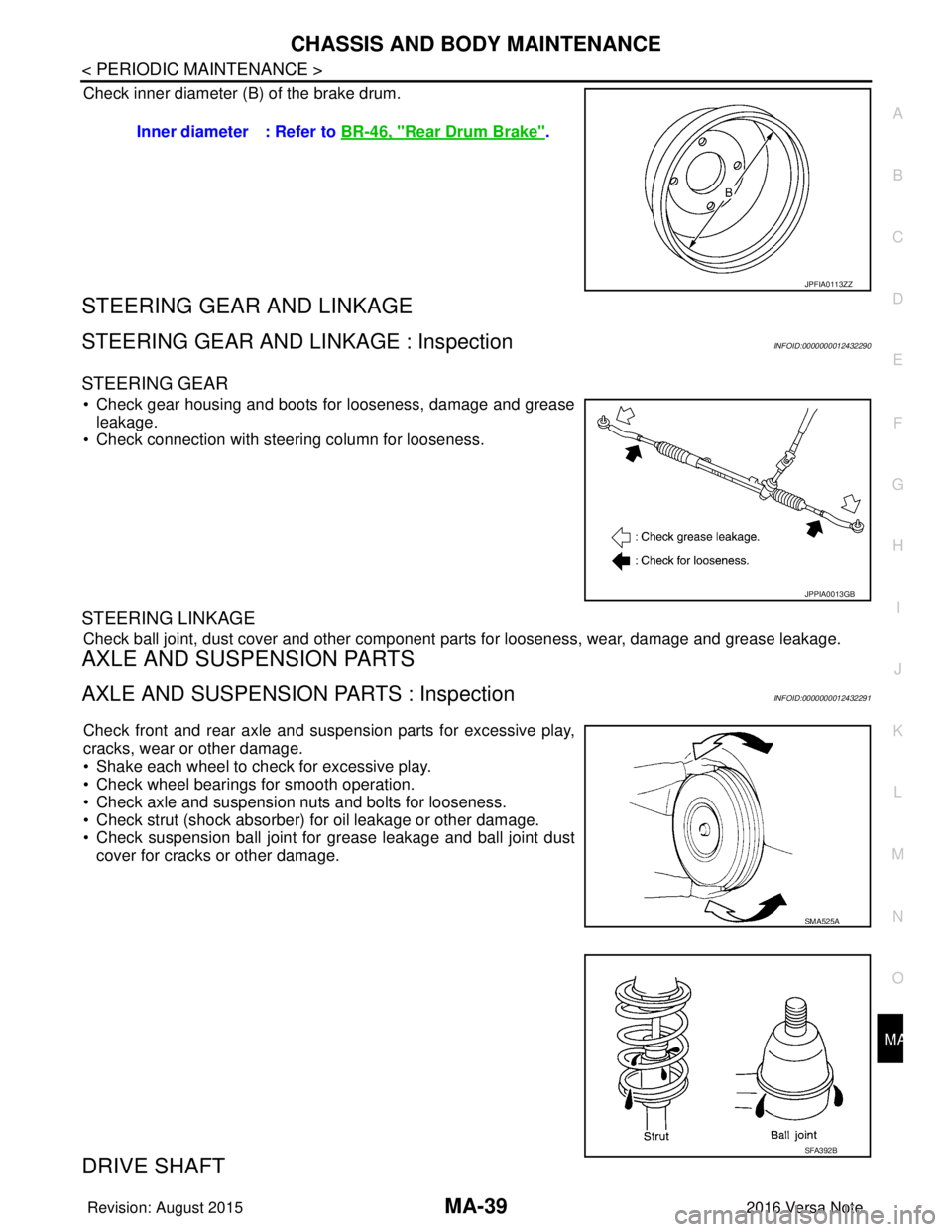
Check inner diameter (B) of the brake drum.
STEERING GEAR AND LINKAGE
STEERING GEAR AND LINKAGE : InspectionINFOID:0000000012432290
STEERING GEAR
• Check gear housing and boots for looseness, damage and grease
leakage.
• Check connection with steering column for looseness.
STEERING LINKAGE
Check ball joint, dust cover and other component parts for looseness, wear, damage and grease leakage.
AXLE AND SUSPENSION PARTS
AXLE AND SUSPENSION PARTS : InspectionINFOID:0000000012432291
Check front and rear axle and suspension parts for excessive play,
cracks, wear or other damage.
• Shake each wheel to check for excessive play.
• Check wheel bearings for smooth operation.
• Check axle and suspension nuts and bolts for looseness.
• Check strut (shock absorber) for oil leakage or other damage.
• Check suspension ball joint for grease leakage and ball joint dust
cover for cracks or other damage.
DRIVE SHAFT
Inner diameter : Refer to BR-46, "Rear Drum Brake".
JPFIA0113ZZ
JPPIA0013GB
SMA525A
SFA392B
Revision: August 2015 2016 Versa Note
cardiagn.com
Page 2416 of 3641
![NISSAN NOTE 2016 Service Repair Manual MWI-58
< SYSTEM DESCRIPTION >[TYPE B]
COMPONENT PARTS
SYSTEM DESCRIPTION
COMPONENT PARTS
METER SYSTEM
METER SYSTEM : Component Parts LocationINFOID:0000000012432599
A. Steering wheel
B. Combination me NISSAN NOTE 2016 Service Repair Manual MWI-58
< SYSTEM DESCRIPTION >[TYPE B]
COMPONENT PARTS
SYSTEM DESCRIPTION
COMPONENT PARTS
METER SYSTEM
METER SYSTEM : Component Parts LocationINFOID:0000000012432599
A. Steering wheel
B. Combination me](/manual-img/5/57363/w960_57363-2415.png)
MWI-58
< SYSTEM DESCRIPTION >[TYPE B]
COMPONENT PARTS
SYSTEM DESCRIPTION
COMPONENT PARTS
METER SYSTEM
METER SYSTEM : Component Parts LocationINFOID:0000000012432599
A. Steering wheel
B. Combination meter C. View with rear lower seat cushion pad
and inspection hole cover removed.
No. Component Function
1. Parking brake switch Transmits the parking brake switch signal to the combination meter.
2. ABS actuator and electric unit (control unit) Transmits the vehicle speed signal to the combination meter via CAN communica-
tion.
Refer to BRC-7, "
Component Parts Location" for detailed installation location.
ALNIA1658GB
Revision: August 2015
2016 Versa Note
cardiagn.com
Page 2417 of 3641
![NISSAN NOTE 2016 Service Repair Manual MWI
COMPONENT PARTSMWI-59
< SYSTEM DESCRIPTION > [TYPE B]
C
D
E
F
G H
I
J
K L
M B A
O P
METER SYSTEM : Combination MeterINFOID:0000000012432600
The combination meter controls the following items a cco NISSAN NOTE 2016 Service Repair Manual MWI
COMPONENT PARTSMWI-59
< SYSTEM DESCRIPTION > [TYPE B]
C
D
E
F
G H
I
J
K L
M B A
O P
METER SYSTEM : Combination MeterINFOID:0000000012432600
The combination meter controls the following items a cco](/manual-img/5/57363/w960_57363-2416.png)
MWI
COMPONENT PARTSMWI-59
< SYSTEM DESCRIPTION > [TYPE B]
C
D
E
F
G H
I
J
K L
M B A
O P
METER SYSTEM : Combination MeterINFOID:0000000012432600
The combination meter controls the following items a ccording to the signals received from each unit via CAN
communication and the signals from switches and sensors:
• Measuring instruments
• Indicator lamps
• Warning lamps
• Meter illumination control
• Information display
ARRANGEMENT OF COMBINATION METER
3. Washer fluid level switch Transmits the washer fluid level switch signal to the combination meter (for Cana-
da).
Refer to
WW-6, "
Component Parts Location" for detailed installation location.
4. Engine oil pressure sensor Transmits the engine oil pressure sensor signal to the ECM.
Refer to
EM-93, "
Exploded View" for detailed installation location.
5. Ambient sensor Transmits the ambient sensor signal to the combination meter.
6. TCM Transmits the shift position signal to the combination meter via CAN communica-
tion (with CVT).
Refer to
TM-61, "
CVT CONTROL SYSTEM : Component Parts Location" for de-
tailed installation location.
7. ECM Transmits the following signals to the combination meter via CAN communication:
• Engine speed signal
• Engine coolant temperature signal
• Fuel consumption monitor signal
• Engine oil pressure sensor signal
Refer to
EC-14, "
ENGINE CONTROL SYSTEM : ComponentPartsLocation" for
detailed installation location.
8. BCM Transmits the following signals to the combination meter via CAN communication:
• Door switch signal
• Buzzer signal
Refer to
BCS-6, "
BODY CONTROL SYSTEM : Component Parts Location" (with
Intelligent Key system) or BCS-77, "
BODY CONTROL SYSTEM : Component
Parts Location" (without Intelligent Key system) for detailed installation location.
9. Steering wheel audio control switches
(meter control switch) Transmits the meter control switch signal to the combination meter.
10. Combination meter Refer to MWI-59, "
METER SYSTEM : Combination Meter".
11 . Fuel level sensor unit and fuel pump (fuel
level sensor) Transmits the fuel level sensor signal to the combination meter.
No.
Component Function
AWNIA3630ZZ
Revision: August 2015 2016 Versa Note
cardiagn.com
Page 2426 of 3641
![NISSAN NOTE 2016 Service Repair Manual MWI-68
< SYSTEM DESCRIPTION >[TYPE B]
OPERATION
OPERATION
Switch Name and FunctionINFOID:0000000012432610
ILLUMINATION CONTROL SWITCH/
TRIP ODOMETER RESET SWITCH
STEERING WHEEL AUDIO CONTROL SWITCH (M NISSAN NOTE 2016 Service Repair Manual MWI-68
< SYSTEM DESCRIPTION >[TYPE B]
OPERATION
OPERATION
Switch Name and FunctionINFOID:0000000012432610
ILLUMINATION CONTROL SWITCH/
TRIP ODOMETER RESET SWITCH
STEERING WHEEL AUDIO CONTROL SWITCH (M](/manual-img/5/57363/w960_57363-2425.png)
MWI-68
< SYSTEM DESCRIPTION >[TYPE B]
OPERATION
OPERATION
Switch Name and FunctionINFOID:0000000012432610
ILLUMINATION CONTROL SWITCH/
TRIP ODOMETER RESET SWITCH
STEERING WHEEL AUDIO CONTROL SWITCH (METER CONTROL SWITCH)
AWNIA3606ZZ
Switch name Operation Description
Illumination control switch (1) Turn An illuminance level of the back light of the combination meter can be adjusted.
Trip odometer reset switch (1) Press • The information display screen can be switched.
• The trip meter can be switched between A and B.
• Trip meter A/B can be reset by pressing and holding the trip reset switch.
• Time can be adjusted.
AWNIA3620GB
Switch name
Operation Description
Steering wheel audio control switch
(meter control switch) (2) Press• Trip computer modes can be selected.
• Trip computer value displayed can be reset by pressing and holding the meter
control switch for 1 second or more.
• All trip computer values displayed can be reset by pressing and holding the
meter control switch for 3 seconds or more.
Revision: August 2015 2016 Versa Note
cardiagn.com
Page 2734 of 3641

RSU-6
< PERIODIC MAINTENANCE >
WHEEL ALIGNMENT
WHEEL ALIGNMENT
InspectionINFOID:0000000012431922
DESCRIPTION
Measure the wheel alignment under unladen conditions.
NOTE:
“Unladen conditions” means that fuel, engine coolant, and lubricants are full. Spare tire, jack, hand tools and
mats are in designated positions.
PRELIMINARY
Check the following:
1. Tires for improper air pressure and wear.
2. Road wheels for runout. Refer to WT-44, "
Inspection".
3. Wheel bearing axial end play. Refer to RAX-10, "
Wheel Bearing".
4. Shock absorber operation.
5. Each mounting part of suspension for looseness and deformation.
6. Rear suspension beam for cracks, deformation, and other damage.
7. Vehicle height (posture).
GENERAL INFORMATION AND RECOMMENDATIONS
1. A Four-Wheel Thrust Alignment should be performed. • This type of alignment is recommended for any NISSAN/INFINITI vehicle.
• The four-wheel “thrust” process helps ensure that the vehicle is properly aligned and the steering wheel
is centered.
• The alignment machine itself should be capabl e of accepting any NISSAN/INFINITI vehicle.
• The alignment machine should be checked to ensure that it is level.
2. Make sure the alignment machine is properly calibrated. • Your alignment machine should be regularly calibrated in order to give correct information.
• Check with the manufacturer of your specific al ignment machine for their recommended Service/Cali-
bration Schedule.
THE ALIGNMENT PROCESS
IMPORTANT: Use only the alignment specifications listed in this Service Manual. Refer to RSU-15, "Wheel
Alignment (Unladen*1)".
1. When displaying the alignment settings, many alignment machines use “indicators”: (Green/red, plus or minus, Go/No Go). Do NOT use these indicators.
• The alignment specifications programmed into your alignment machine that operate these indicators may not be correct.
• This may result in an ERROR.
2. Most camera-type alignment machines are equipped with both "Rolling Compensation" method and optional "Jacking Compensation" method to "com pensate" the alignment targets or head units.
"Rolling Compensation" is the preferred method.
• If using the "Rolling Compensation" method, after installing the alignment targets or head units, push or pull on the rear wheel to move the vehicle. Do not push or pull the vehicle body.
• If using the "Jacking Compensation" method, after in stalling the alignment targets or head units, raise
the vehicle and rotate the wheels 1/2 turn both ways.
NOTE:
Do not use the "rolling compensation" if you are using sensor-type alignment equipment.
• Follow all instructions for the alignment machine you're using for more information.
CAMBER INSPECTION
• Measure camber of both right and left wheels with a suitable alignment gauge.
• If it is out of the specificati on value, inspect and replace any damaged or worn rear suspension parts.
Camber : Refer to RSU-15, "
Wheel Alignment
(Unladen*1)".
Revision: August 2015
2016 Versa Note
cardiagn.com
Page 2742 of 3641

RSU-14
< REMOVAL AND INSTALLATION >
REAR SUSPENSION BEAM
• Perform the final tightening of the rear suspension beam nuts and bolts under unladen conditions with thetires on level ground.
• Adjust the parking brake. Refer to PB-4, "
Inspection and Adjustment".
• Fill the hydraulic brake system. Refer to BR-12, "
Refilling".
• Bleed the hydraulic brake system. Refer to BR-13, "
Bleeding Brake System".
• Complete the inspection. Refer to BR-12, "
Inspection".
InspectionINFOID:0000000012431932
INSPECTION AFTER REMOVAL
Check the rear suspension beam for deformation, cracks or damage. Replace the parts if necessary.
INSPECTION AFTER INSTALLATION
1. Check the wheel sensor harness to be sure the connectors are fully seated.
2. Check the neutral position of the steering angle sensor. Refer to BRC-55, "
ADJUSTMENT OF STEERING
ANGLE SENSOR NEUTRAL POSITION : Description".
3. Check the wheel alignment. Refer to RSU-6, "
Inspection".
Revision: August 2015 2016 Versa Note
cardiagn.com