2016 NISSAN NOTE trans
[x] Cancel search: transPage 2986 of 3641
![NISSAN NOTE 2016 Service Repair Manual DIAGNOSIS SYSTEM (IPDM E/R)SEC-129
< SYSTEM DESCRIPTION > [WITHOUT INTELLIGENT KEY SYSTEM]
C
D
E
F
G H
I
J
L
M A
B
SEC
N
O P
ECU IDENTIFICATION
The IPDM E/R part number is displayed.
SELF DIAGNOSTIC R NISSAN NOTE 2016 Service Repair Manual DIAGNOSIS SYSTEM (IPDM E/R)SEC-129
< SYSTEM DESCRIPTION > [WITHOUT INTELLIGENT KEY SYSTEM]
C
D
E
F
G H
I
J
L
M A
B
SEC
N
O P
ECU IDENTIFICATION
The IPDM E/R part number is displayed.
SELF DIAGNOSTIC R](/manual-img/5/57363/w960_57363-2985.png)
DIAGNOSIS SYSTEM (IPDM E/R)SEC-129
< SYSTEM DESCRIPTION > [WITHOUT INTELLIGENT KEY SYSTEM]
C
D
E
F
G H
I
J
L
M A
B
SEC
N
O P
ECU IDENTIFICATION
The IPDM E/R part number is displayed.
SELF DIAGNOSTIC RESULT
Refer to PCS-20, "DTCIndex".
DATA MONITOR
ACTIVE TEST
Data Monitor The IPDM E/R input/output data is displayed in real time.
Active Test The IPDM E/R activates outputs to test components.
CAN Diag Support Mntr The result of transmit/receive diagnosis of CAN communication is displayed.
Direct Diagnostic Mode
Description
Monitor Item [Unit]Main
Signals Description
MOTOR FAN REQ [1/2/3/4] ×Indicates cooling fan speed signal received from ECM on CAN communication
line
AC COMP REQ [On/Off] ×Indicates A/C compressor request signal received from ECM on CAN commu-
nication line
TAIL&CLR REQ [On/Off] ×Indicates position light request signal
received from BCM on CAN communica-
tion line
HL LO REQ [On/Off] ×Indicates low beam request signal received from BCM on CAN communication
line
HL HI REQ [On/Off] ×Indicates high beam request signal received from BCM on CAN communication
line
FR FOG REQ [On/Off] ×Indicates front fog light request signal received from BCM on CAN communica-
tion line
FR WIP REQ [Stop/1LOW/Low/Hi] ×Indicates front wiper request signal received from BCM on CAN communication
line
WIP AUTO STOP [STOP P/ACT P] ×Indicates condition of front wiper auto stop signal
WIP PROT [Off/BLOCK] ×Indicates condition of front wiper fail-safe operation
IGN RLY1 -REQ [On/Off] Indicates ignition switch ON signal received from BCM on CAN communication
line
IGN RLY [On/Off] ×Indicates condition of ignition relay
PUSH SW [On/Off] Indicates condition of push-button ignition switch
INTER/NP SW [On/Off] Indicates condition of CVT shift position
ST RLY CONT [On/Off] Indicates starter relay status signal received from BCM on CAN communication
line
IHBT RLY -REQ [On/Off] Indicates starter control relay signal received from BCM on CAN communication
line
ST/INHI RLY [Off/ ST /INHI] Indicates condition of starter relay and starter control relay
DETENT SW [On/Off] Indicates condition of CVT shift selector (park position switch)
DTRL REQ [Off] Indicates daytime running light request signal received from BCM on CAN com-
munication line
THFT HRN REQ [On/Off] Indicates theft warning horn request signal received from BCM on CAN commu-
nication line
HORN CHIRP [On/Off] Indicates horn reminder signal received from BCM on CAN communication line
Test item Description
HORN This test is able to check horn operation [On].
FRONT WIPER This test is able to check wiper motor operation [Hi/Lo/Off].
Revision: August 2015 2016 Versa Note
cardiagn.com
Page 3111 of 3641
SRC-94
< DTC/CIRCUIT DIAGNOSIS >
U1000 CAN COMM CIRCUIT
U1000 CAN COMM CIRCUIT
DescriptionINFOID:0000000012430674
CAN (Controller Area Network) is a serial communication system for real time application. It is an on-vehicle
multiplex communication system with high data communication speed and excellent error detection ability.
Many electronic control units are equipped into vehicl es, and each control unit shares information and links
with other control units during operation. With CAN co mmunication, control units are connected with two com-
munication lines (CAN-H line, CAN-L line) allowing a hi gh rate of information transmission with less wiring.
Each control unit transmits and receives data but selectively reads required data only. Refer to LAN-30, "
CAN
COMMUNICATION SYSTEM : CAN Communication Signal Chart".
DTC LogicINFOID:0000000012430675
DTC DETECTION LOGIC
DTC CONFIRMATION PROCEDURE
1.PERFORM SELF-DIAGNOSIS
1. Turn ignition switch ON and wait for 7 seconds or more.
2. Using CONSULT, perform SELF-DIAGNOSIS RESULTS of AIR BAG.
3. Check if any DTC is displayed in the self-diagnosis results.
Is DTC detected?
YES >> Refer to SRC-94, "Diagnosis Procedure".
NO >> Refer to GI-42, "
Intermittent Incident".
Diagnosis ProcedureINFOID:0000000012430676
1.CHECK CAN COMMUNICATION SYSTEM
Check CAN communication system. Refer to LAN-16, "
Trouble Diagnosis Flow Chart".
>> Inspection End.
CONSULT name DTCDTC detecting condition Repair order
CAN COMMUNICATION FAILURE U1000 When air bag diagnosis sensor unit is not
transmitting or receiving CAN communi-
cation signals for 2 or more seconds.Refer to SRC-94, "
Diagnosis
Procedure".
Revision: August 2015
2016 Versa Note
cardiagn.com
Page 3157 of 3641

COMPONENT PARTSSTR-5
< SYSTEM DESCRIPTION >
C
DE
F
G H
I
J
K L
M A
STR
NP
O
STARTING SYSTEM (WITHOUT INTELL
IGENT KEY) : Component Description
INFOID:0000000012432061
STARTING SYSTEM (WITH INTELLIGENT KEY)
No.Component part Description
1. IPDM E/R CPU inside IPDM E/R operates the starter control relay when
the ignition switch is in the start position.
2. Transmission range switch (CVT Models) Supplies power to the starter co
ntrol relay (inside IPDM E/R)
when the selector lever is shifted into the P or N position.
3. Starter motor The starter motor plunger closes and the motor is supplied
with battery power, which in turn cranks the engine, when the
S terminal is supplied with electric power.
4. Clutch interlock switch (M/T Models) Clutch interlock switch supplies power to the coil side of the
starter control relay when the clutch pedal is depressed to
crank the engine.
Revision: August 2015
2016 Versa Note
cardiagn.com
Page 3158 of 3641
STR-6
< SYSTEM DESCRIPTION >
COMPONENT PARTS
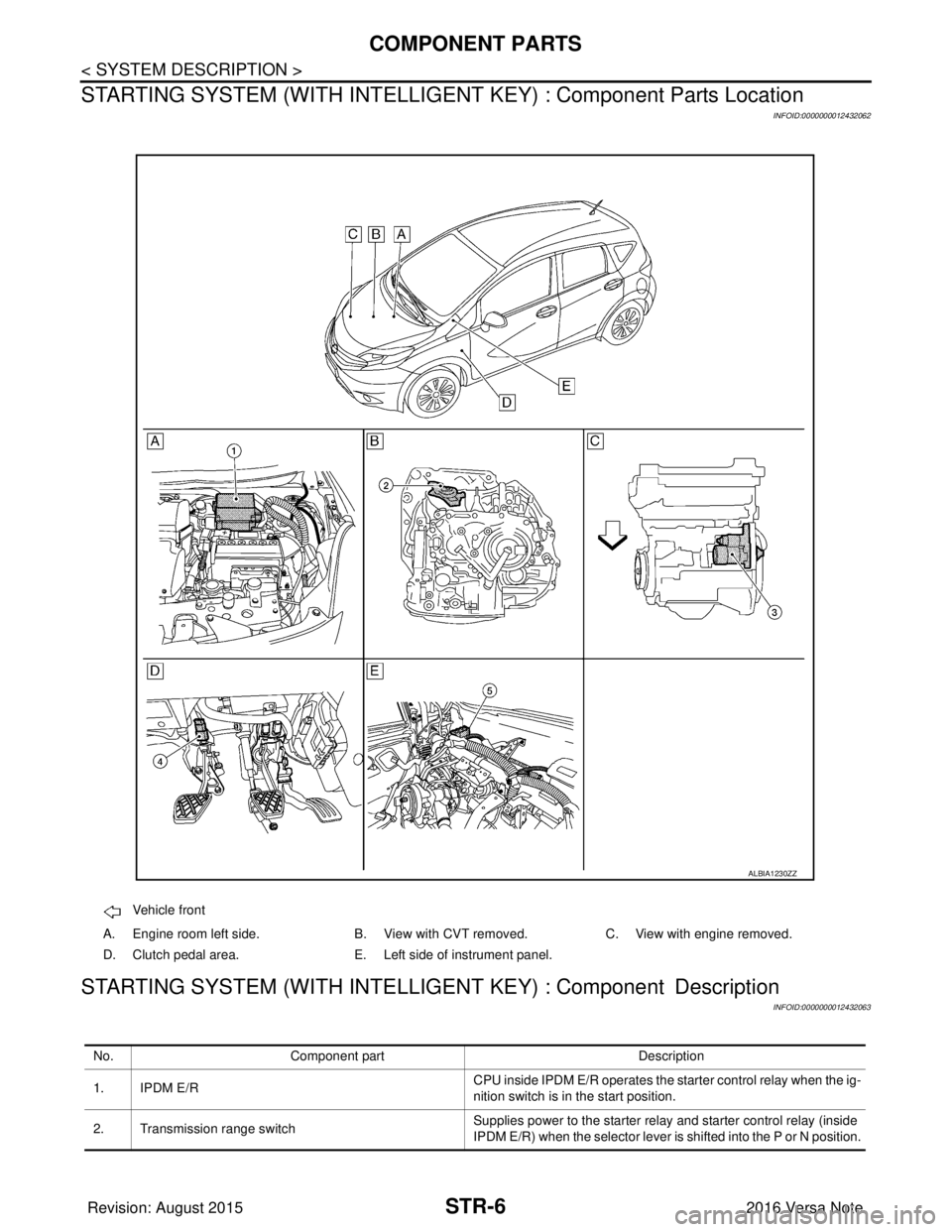
STARTING SYSTEM (WITH INTELLIGEN T KEY) : Component Parts Location
INFOID:0000000012432062
STARTING SYSTEM (WITH INTELLIGENT KEY) : Component Description
INFOID:0000000012432063
Vehicle front
A. Engine room left side. B. View with CVT removed. C. View with engine removed.
D. Clutch pedal area. E. Left side of instrument panel.
ALBIA1230ZZ
No. Component part Description
1. IPDM E/R CPU inside IPDM E/R operates the starter control relay when the ig-
nition switch is in the start position.
2. Transmission range switch Supplies power to the starter relay
and starter control relay (inside
IPDM E/R) when the selector lever is shifted into the P or N position.
Revision: August 2015 2016 Versa Note
cardiagn.com
Page 3161 of 3641

SYSTEMSTR-9
< SYSTEM DESCRIPTION >
C
DE
F
G H
I
J
K L
M A
STR
NP
O
STARTING SYSTEM (WITH INTELL
IGENT KEY) : System DiagramINFOID:0000000012432066
STARTING SYSTEM (WITH INTELLIG ENT KEY) : System DescriptionINFOID:0000000012432067
• When the selector lever is in the P or N position, power is supplied to starter relay and starter control relay by
the transmission range switch. The BCM and IPDM E/R (C PU) will detect the selector lever position by the
input signal.
• When the starter operating condition is met, the IPDM E/R will turn the starter control relay ON by starter
control relay control signal.
• When engine cranking condition is met, the BCM turns ON the starter relay by starter control relay signal.
• Then battery power is supplied to starter motor (“S” terminal) through the starter control relay and starter
relay.
ALBIA1231GB
Revision: August 2015 2016 Versa Note
cardiagn.com
Page 3188 of 3641
STC-4
< SYSTEM DESCRIPTION >
COMPONENT PARTS
SYSTEM DESCRIPTION
COMPONENT PARTS
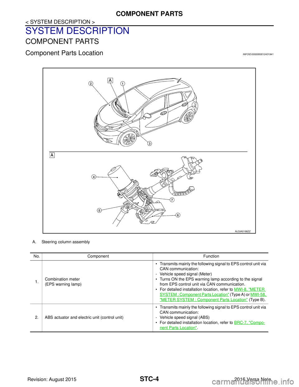
Component Parts LocationINFOID:0000000012431941
A. Steering column assemblyNo. Component Function
1. Combination meter
(EPS warning lamp) • Transmits mainly th
e following signal to EPS control unit via
CAN communication:
- Vehicle speed signal (Meter)
• Turns ON the EPS warning lamp according to the signal from EPS control unit via CAN communication.
• For detailed installation location, refer to MWI-8, "
METER
SYSTEM : Component Parts Location" (Type A) or MWI-58,
"METER SYSTEM : Component Parts Location" (Type B).
2. ABS actuator and electric unit (control unit) • Transmits mainly th
e following signal to EPS control unit via
CAN communication:
- Vehicle speed signal (ABS)
• For detailed installation location, refer to BRC-7, "
Compo-
nent Parts Location".
ALGIA0166ZZ
Revision: August 2015 2016 Versa Note
cardiagn.com
Page 3189 of 3641
COMPONENT PARTSSTC-5
< SYSTEM DESCRIPTION >
C
DE
F
H I
J
K L
M A
B
STC
N
O P
EPS Control UnitINFOID:0000000012431942
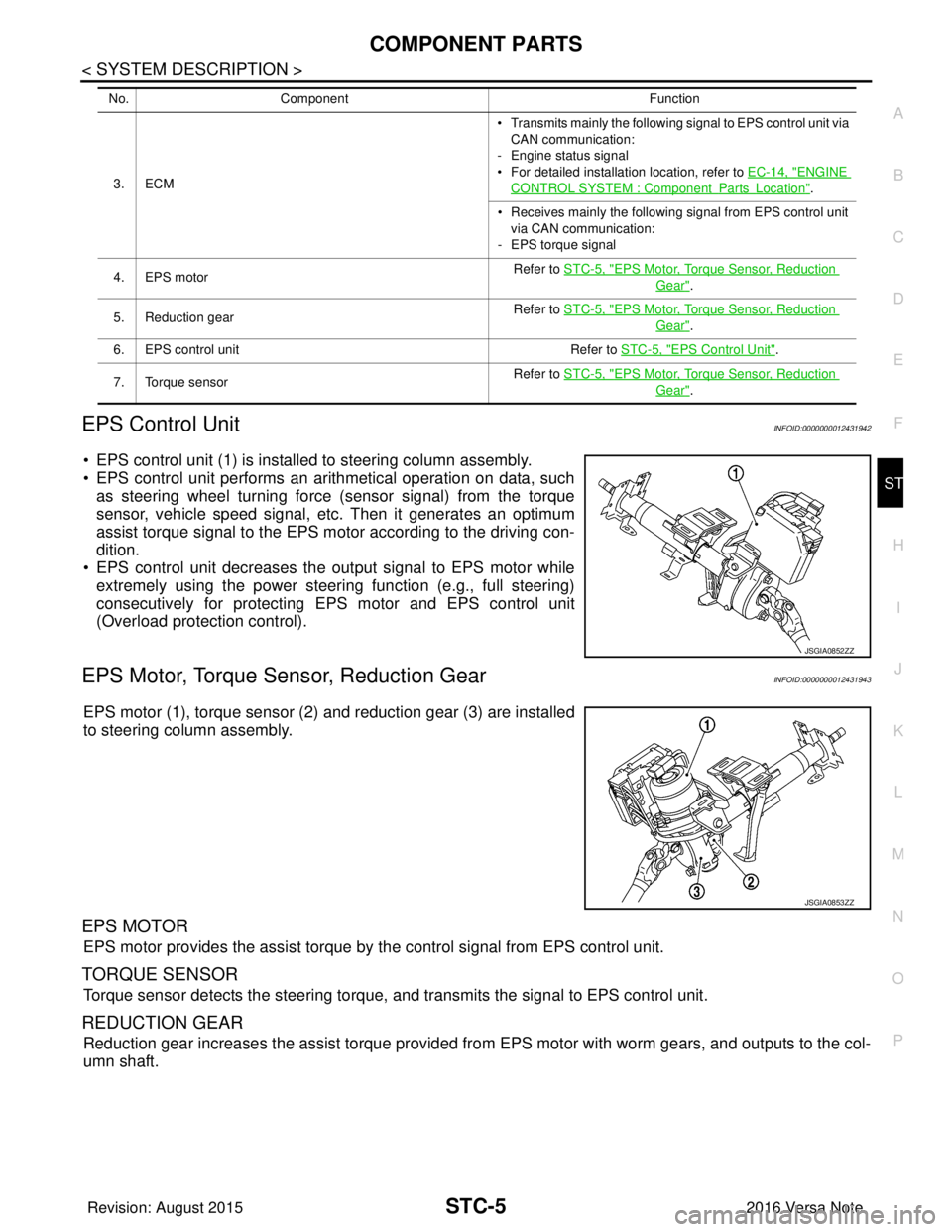
• EPS control unit (1) is installed to steering column assembly.
• EPS control unit performs an arithmetical operation on data, such as steering wheel turning force (sensor signal) from the torque
sensor, vehicle speed signal, etc. Then it generates an optimum
assist torque signal to the EPS motor according to the driving con-
dition.
• EPS control unit decreases the output signal to EPS motor while
extremely using the power steering function (e.g., full steering)
consecutively for protecting EPS motor and EPS control unit
(Overload protection control).
EPS Motor, Torque Sensor, Reduction GearINFOID:0000000012431943
EPS motor (1), torque sensor (2) and reduction gear (3) are installed
to steering column assembly.
EPS MOTOR
EPS motor provides the assist torque by the control signal from EPS control unit.
TORQUE SENSOR
Torque sensor detects the steering torque, and transmits the signal to EPS control unit.
REDUCTION GEAR
Reduction gear increases the assist torque provided from EPS motor with worm gears, and outputs to the col-
umn shaft.
3. ECM • Transmits mainly th
e following signal to EPS control unit via
CAN communication:
- Engine status signal
• For detailed installation location, refer to EC-14, "ENGINE
CONTROL SYSTEM : ComponentPartsLocation".
• Receives mainly the following signal from EPS control unit
via CAN communication:
- EPS torque signal
4. EPS motor Refer to STC-5, "
EPS Motor, Torque Sensor, Reduction
Gear".
5. Reduction gear Refer to STC-5, "
EPS Motor, Torque Sensor, Reduction
Gear".
6. EPS control unit Refer to STC-5, "
EPS Control Unit".
7. Torque sensor Refer to STC-5, "
EPS Motor, Torque Sensor, Reduction
Gear".
No.
Component Function
JSGIA0852ZZ
JSGIA0853ZZ
Revision: August 2015 2016 Versa Note
cardiagn.com
Page 3212 of 3641
STC-28
< DTC/CIRCUIT DIAGNOSIS >
U1000 CAN COMM CIRCUIT
U1000 CAN COMM CIRCUIT
DescriptionINFOID:0000000012431968
CAN (Controller Area Network) is a serial communication line for real time application. It is an on-vehicle mul-
tiplex communication line with high data communication speed and excellent error detection ability. Many elec-
tronic control units are equipped onto a vehicle, and each control unit shares information and links with other
control units during operation (not independent). In CA N communication, control units are connected with 2
communication lines (CAN-H line, CAN-L line) allowing a high rate of information transmission with less wiring.
Each control unit communicate data but selectively reads required data only.
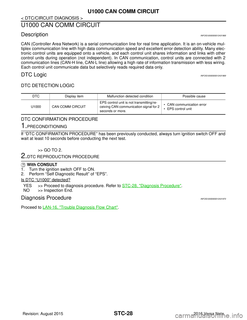
DTC LogicINFOID:0000000012431969
DTC DETECTION LOGIC
DTC CONFIRMATION PROCEDURE
1.PRECONDITIONING
If “DTC CONFIRMATION PROCEDURE” has been previously conducted, always turn ignition switch OFF and
wait at least 10 seconds before conducting the next test.
>> GO TO 2.
2.DTC REPRODUCTION PROCEDURE
With CONSULT
1. Turn the ignition switch OFF to ON.
2. Perform “Self Diagnostic Result” of “EPS”.
Is DTC
“U1000” detected?
YES >> Proceed to diagnosis procedure. Refer to STC-28, "Diagnosis Procedure".
NO >> Inspection End.
Diagnosis ProcedureINFOID:0000000012431970
Proceed to LAN-16, "Trouble Diagnosis Flow Chart".
DTC Display item Malfunction detected condition Possible cause
U1000 CAN COMM CIRCUIT EPS control unit is not transmitting/re-
ceiving CAN communication signal for 2
seconds or more.• CAN communication error
• EPS control unit
Revision: August 2015
2016 Versa Note
cardiagn.com