2016 NISSAN NOTE start
[x] Cancel search: startPage 1752 of 3641
EXL-100
< PERIODIC MAINTENANCE >
FRONT FOG LAMP AIMING ADJUSTMENT
FRONT FOG LAMP AIMING ADJUSTMENT
InspectionINFOID:0000000012432830
PREPARATION BEFORE ADJUSTING
Before performing aiming adjustment procedure, check the following:
• Ensure all tires are inflated to correct pressure.
• Place vehicle and screen on level surface.
• Ensure there is no load in vehicle other than the driver (or equivalent weight placed in driver's position).
• Coolant and engine oil filled to correct level, and fuel tank full.
• Remove cargo and/or luggage to maintain an unloaded vehicle condition.
• Confirm spare tire, jack and tools are properly stowed.
• Carefully wipe off any dirt from fog lamp lens. CAUTION:
Do not use organic solvent (thinner, gasoline etc.)
• Place a driver or equivalent weight of 68.5 kg (150 lb) on the driver seat.
• By hand, bounce the front and rear of the vehicle to settle the suspension and eliminate any static load.
• Place the front tires in the straight ahead position.
• Aim each headlamp individually and ensure other headlamp beam pattern is blocked from screen.
NOTE:
• For headlamp aiming details, refer to regulations in your area.
• By regulation, no means for horizontal aim adjustment is provided from the factory; only vertical aim is
adjustable.
• Use adjusting screw to perform aiming adjustment.
• Perform headlamp aiming if:
- The vehicle front body has been repaired.
- The front combination lamp has been removed or replaced.
- Any outfitting has been installed.
- The vehicle’s standard load condition has been substantially increased.
AIMING ADJUSTMENT SCREW
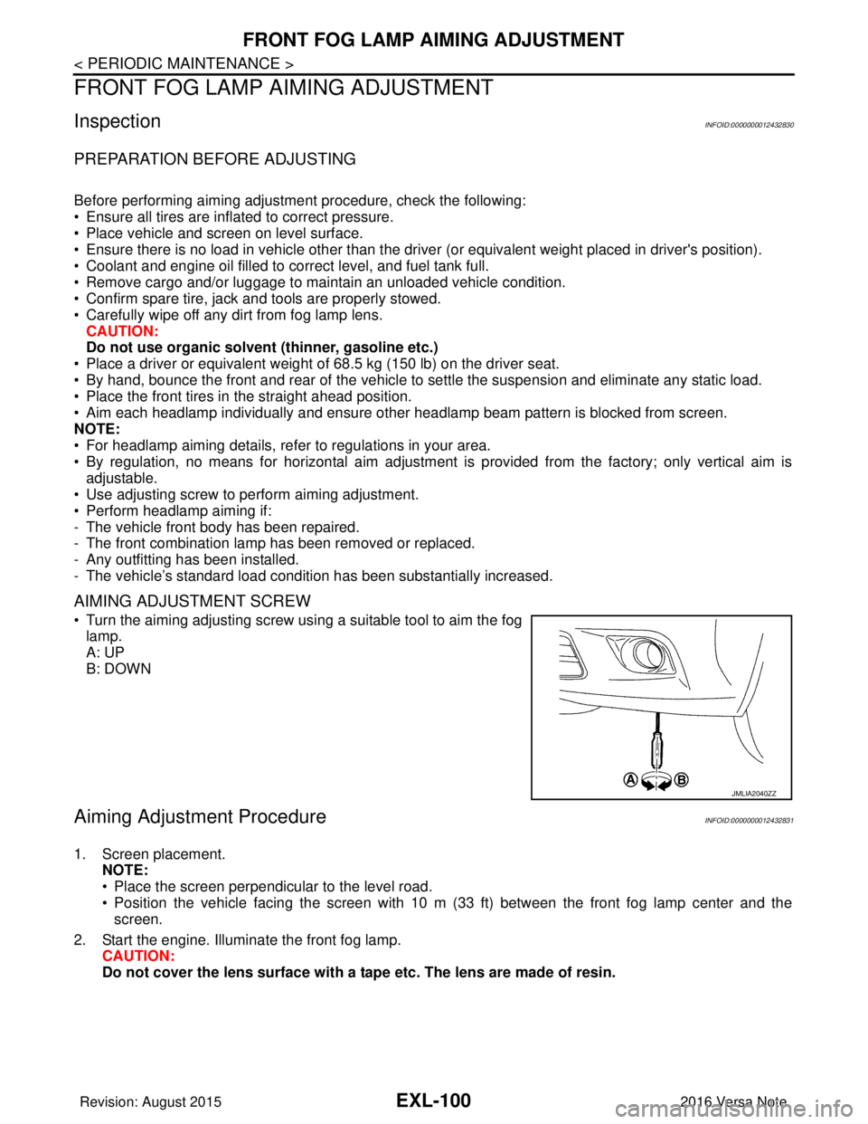
• Turn the aiming adjusting screw using a suitable tool to aim the fog
lamp.
A: UP
B: DOWN
Aiming Adjustment ProcedureINFOID:0000000012432831
1. Screen placement. NOTE:
• Place the screen perpendicular to the level road.
• Position the vehicle facing the screen with 10 m (33 ft) between the front fog lamp center and thescreen.
2. Start the engine. Illuminate the front fog lamp. CAUTION:
Do not cover the lens surface with a tape etc. The lens are made of resin.
JMLIA2040ZZ
Revision: August 2015 2016 Versa Note
cardiagn.com
Page 1786 of 3641
SQUEAK AND RATTLE TROUBLE DIAGNOSESEXT-19
< SYMPTOM DIAGNOSIS >
C
DE
F
G H
I
J
L
M A
B
EXT
N
O P
INSTRUMENT PANEL
Most incidents are caused by contact and movement between:
1. Cluster lid A and the instrument panel
2. Acrylic lens and combination meter housing
3. Instrument panel to front pillar finisher
4. Instrument panel to windshield
5. Instrument panel pins
6. Wiring harnesses behind the combination meter
7. A/C defroster duct and duct joint
These incidents can usually be located by tapping or moving the components to duplicate the noise or by
pressing on the components while driving to stop the noi se. Most of these incidents can be repaired by apply-
ing felt cloth tape or silicone spray (in hard to reach areas). Urethane pads can be used to insulate wiring har-
ness.
CAUTION:
Do not use silicone spray to isolate a squeak or ra ttle. If you saturate the area with silicone, you will
not be able to recheck the repair.
CENTER CONSOLE
Components to pay attention to include:
1. Shift selector assembly cover to finisher
2. A/C control unit and cluster lid C
3. Wiring harnesses behind audio and A/C control unit
The instrument panel repair and isolation pr ocedures also apply to the center console.
DOORS
Pay attention to the:
1. Finisher and inner panel making a slapping noise
2. Inside handle escutcheon to door finisher
3. Wiring harnesses tapping
4. Door striker out of alignment causing a popping noise on starts and stops
Tapping or moving the components or pressing on them while driving to duplicate the conditions can isolate
many of these incidents. You can usually insulate the ar eas with felt cloth tape or insulator foam blocks from
the NISSAN Squeak and Rattle Kit (J-50397) to repair the noise.
TRUNK
Trunk noises are often caused by a loose jack or loose items put into the trunk by the owner.
In addition look for:
1. Trunk lid bumpers out of adjustment
2. Trunk lid striker out of adjustment
3. The trunk lid torsion bars knocking together
4. A loose license plate or bracket
Most of these incidents can be repaired by adjusting, se curing or insulating the item(s) or component(s) caus-
ing the noise.
SUNROOF/HEADLINING
Noises in the sunroof/headlining area can often be traced to one of the following:
1. Sunroof lid, rail, linkage or seals making a rattle or light knocking noise
2. Sun visor shaft shaking in the holder
3. Front or rear windshield touching headlining and squeaking
Again, pressing on the components to stop the noise while duplicating the conditions can isolate most of these
incidents. Repairs usually consist of insulating with felt cloth tape.
OVERHEAD CONSOLE (FRONT AND REAR)
Overhead console noises are often caused by the cons ole panel clips not being engaged correctly. Most of
these incidents are repaired by pushing up on the c onsole at the clip locations until the clips engage.
In addition look for:
Revision: August 2015 2016 Versa Note
cardiagn.com
Page 1810 of 3641
ROOF SIDE MOLDINGEXT-43
< REMOVAL AND INSTALLATION >
C
DE
F
G H
I
J
L
M A
B
EXT
N
O P
Removal
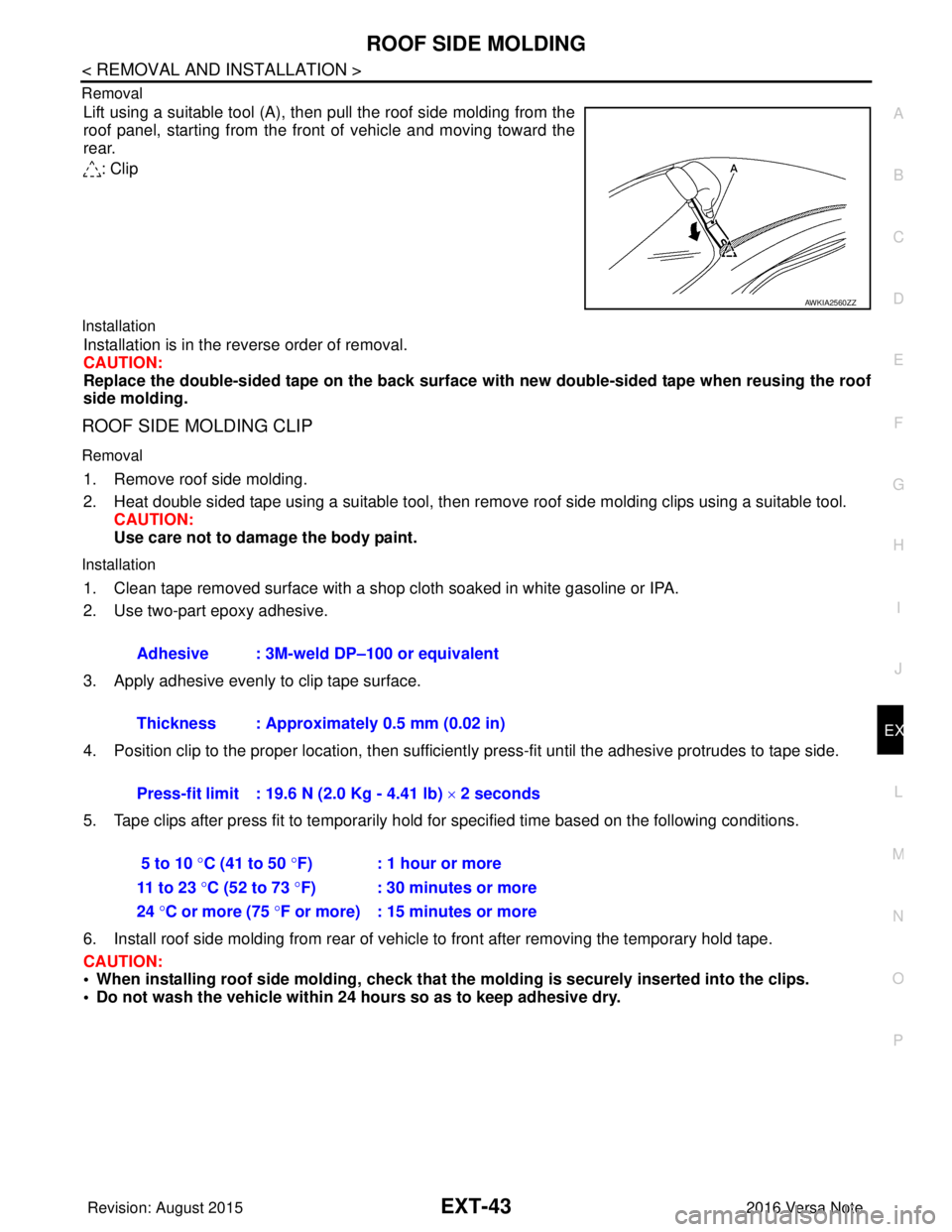
Lift using a suitable tool (A), then pull the roof side molding from the
roof panel, starting from the front of vehicle and moving toward the
rear.
: Clip
Installation
Installation is in the reverse order of removal.
CAUTION:
Replace the double-sided tape on the back surface with new double-sided tape when reusing the roof
side molding.
ROOF SIDE MOLDING CLIP
Removal
1. Remove roof side molding.
2. Heat double sided tape using a suitable tool, then remove roof side molding clips using a suitable tool.
CAUTION:
Use care not to damage the body paint.
Installation
1. Clean tape removed surface with a shop cloth soaked in white gasoline or IPA.
2. Use two-part epoxy adhesive.
3. Apply adhesive evenly to clip tape surface.
4. Position clip to the proper location, then sufficient ly press-fit until the adhesive protrudes to tape side.
5. Tape clips after press fit to temporarily hold for specified time based on the following conditions.
6. Install roof side molding from rear of vehicle to front after removing the temporary hold tape.
CAUTION:
• When installing roof side moldin g, check that the molding is securely inserted into the clips.
• Do not wash the vehicle within 24 hours so as to keep adhesive dry.
AWKIA2560ZZ
Adhesive : 3M-weld DP–100 or equivalent
Thickness : Approximately 0.5 mm (0.02 in)
Press-fit limit : 19.6 N (2.0 Kg - 4.41 lb) × 2 seconds
5 to 10 °C (41 to 50 °F) : 1 hour or more
11 to 23 °C (52 to 73 °F) : 30 minutes or more
24 °C or more (75 °F or more) : 15 minutes or more
Revision: August 2015 2016 Versa Note
cardiagn.com
Page 1812 of 3641
DOOR SASH TAPEEXT-45
< REMOVAL AND INSTALLATION >
C
DE
F
G H
I
J
L
M A
B
EXT
N
O P
Removal and InstallationINFOID:0000000012432187
REMOVAL
Heat door sash tape surface using a suitable tool and remove door sash tape.
CAUTION:
Use care not to damage body paint.
INSTALLATION
CAUTION:
• Degrease door assembly surface for sash tape.
• Grit or dust on surface of sash tape may spoil exterior appearance if not removed. Clean the surface
and check that no grit or dust rema ins before starting the operation.
• Do not reuse blackout tape.
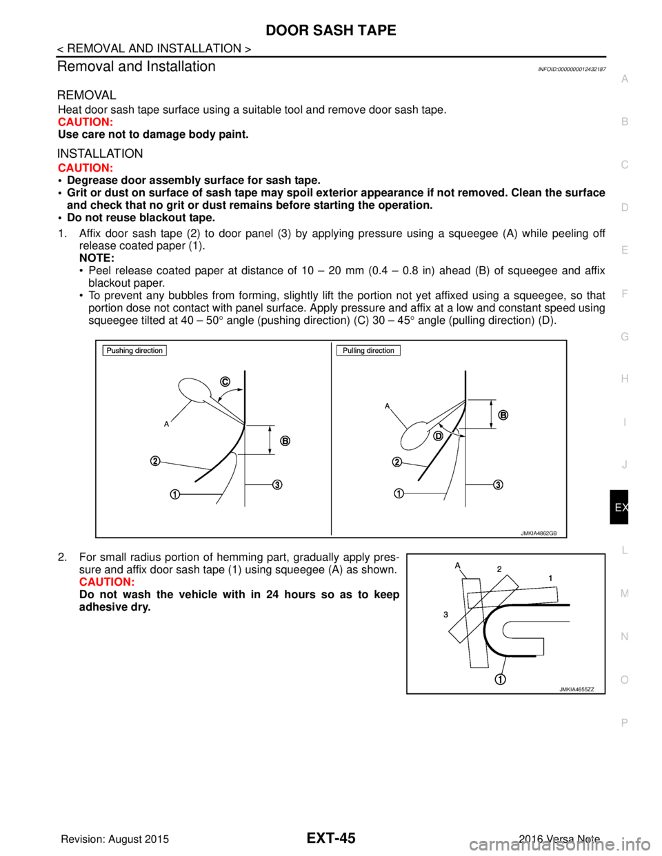
1. Affix door sash tape (2) to door panel (3) by applying pressure using a squeegee (A) while peeling off release coated paper (1).
NOTE:
• Peel release coated paper at distance of 10 – 20 mm (0.4 – 0.8 in) ahead (B) of squeegee and affixblackout paper.
• To prevent any bubbles from forming, slightly lift the portion not yet affixed using a squeegee, so that
portion dose not contact with panel surface. Apply pressure and affix at a low and constant speed using
squeegee tilted at 40 – 50 ° angle (pushing direction) (C) 30 – 45° angle (pulling direction) (D).
2. For small radius portion of hemming part, gradually apply pres- sure and affix door sash tape (1) using squeegee (A) as shown.
CAUTION:
Do not wash the vehicle with in 24 hours so as to keep
adhesive dry.
JMKIA4862GB
JMKIA4655ZZ
Revision: August 2015 2016 Versa Note
cardiagn.com
Page 1869 of 3641
PRECAUTIONSFL-3
< PRECAUTION >
C
DE
F
G H
I
J
K L
M A
FL
NP
O
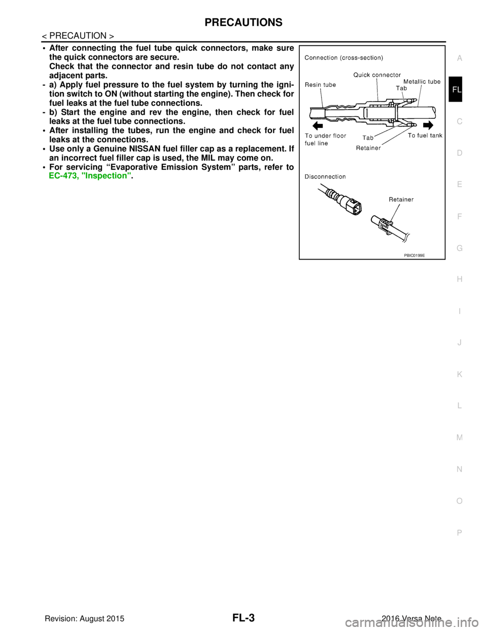
• After connecting the fuel tu
be quick connectors, make sure
the quick connectors are secure.
Check that the connector and r esin tube do not contact any
adjacent parts.
- a) Apply fuel pressure to the fu el system by turning the igni-
tion switch to ON (without starting the engine). Then check for
fuel leaks at the fuel tube connections.
- b) Start the engine and rev the engine, then check for fuel leaks at the fuel tube connections.
• After installing the tubes, run the engine and check for fuel
leaks at the connections.
• Use only a Genuine NISSAN fuel filler cap as a replacement. If
an incorrect fuel fi ller cap is used, the MIL may come on.
• For servicing “Evaporative Emi ssion System” parts, refer to
EC-473, "Inspection".
PBIC0199E
Revision: August 2015 2016 Versa Note
cardiagn.com
Page 1873 of 3641

FUEL LEVEL SENSOR UNIT, FUEL FILTER AND FUEL PUMP ASSEMBLYFL-7
< REMOVAL AND INSTALLATION >
C
DE
F
G H
I
J
K L
M A
FL
NP
O
Remove the quick connector as follows:
• Hold the sides of the connector, push in tabs (B) and pull (A)
out the tube.
• If the connector and the tube are stuck together, push and pull several times until they start to move. Then disconnect them
by pulling.
CAUTION:
• Quick connector (1) can be disconnected when the tabs (F) are depressed completely. Do not twist it more than
necessary.
• Do not use any tools to disconnected quick connector.
• Keep resin tube (C) away from heat. Be especially careful when welding near the resin tube.
• Prevent acid liquid such as battery electrolyte, etc. from
getting on resin tube.
• Do not bend or twist resin tube during installation and dis- connection.
• Do not remove the remaining retainer (2) on hard tube (or
the equivalent) (A) except when resin tube or retainer is
replaced.
• When resin tube or hard tube (or the equivalent) is
replaced, also replace retainer with new one.
• To keep the connecting portio n clean and to avoid dam-
age and foreign materials, cover them completely with
plastic bags (A) or something similar.
JPBIA0134ZZ
(B) : Connection (cross-section)
(D) : To under floor fuel line
(E) : To fuel tank
(G) : Disconnection
JPBIA0130ZZ
JPBIA0135ZZ
Revision: August 2015 2016 Versa Note
cardiagn.com
Page 1875 of 3641
FUEL LEVEL SENSOR UNIT, FUEL FILTER AND FUEL PUMP ASSEMBLYFL-9
< REMOVAL AND INSTALLATION >
C
DE
F
G H
I
J
K L
M A
FL
NP
O
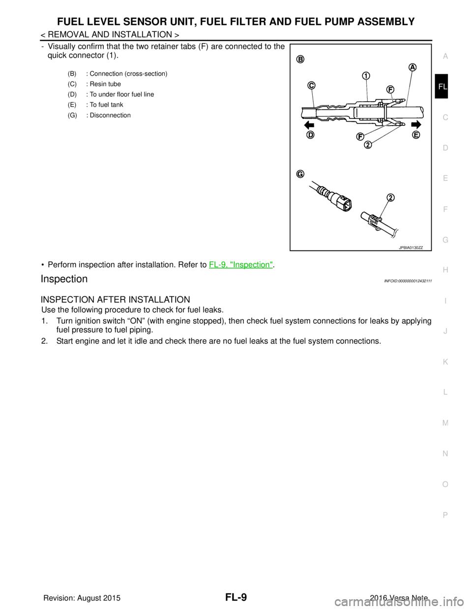
- Visually confirm that the two retainer tabs (F) are connected to the
quick connector (1).
• Perform inspection after installation. Refer to FL-9, "
Inspection".
InspectionINFOID:0000000012432111
INSPECTION AFTER INSTALLATION
Use the following procedure to check for fuel leaks.
1. Turn ignition switch “ON” (with engine stopped), then check fuel system connections for leaks by applying
fuel pressure to fuel piping.
2. Start engine and let it idle and check there are no fuel leaks at the fuel system connections.
(B) : Connection (cross-section)
(C) : Resin tube
(D) : To under floor fuel line
(E) : To fuel tank
(G) : Disconnection
JPBIA0130ZZ
Revision: August 2015 2016 Versa Note
cardiagn.com
Page 1877 of 3641
FUEL TANKFL-11
< REMOVAL AND INSTALLATION >
C
DE
F
G H
I
J
K L
M A
FL
NP
O
3. Open fuel filler lid.
4. Open fuel filler cap and release
the pressure inside fuel tank.
5. Remove the rear seat cushion. Refer to SE-26, "
SEAT CUSHION : Removal and Installation".
6. Remove the inspection hole cover. NOTE:
Inspection hole cover is held by an adhesive.
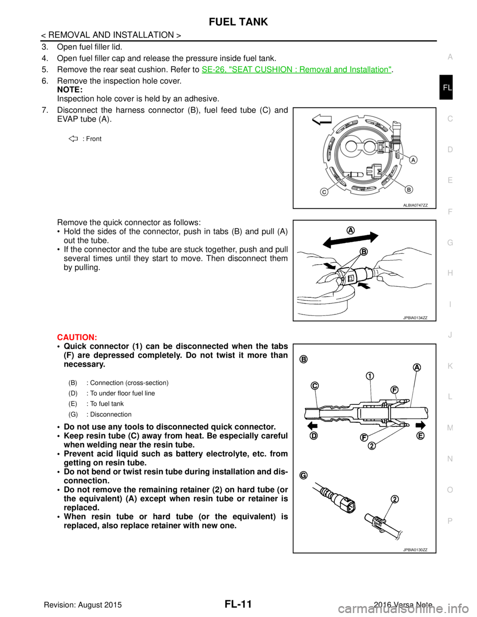
7. Disconnect the harness connector (B), fuel feed tube (C) and
EVAP tube (A).
Remove the quick connector as follows:
• Hold the sides of the connector, push in tabs (B) and pull (A) out the tube.
• If the connector and the tube are stuck together, push and pull several times until they start to move. Then disconnect them
by pulling.
CAUTION:
• Quick connector (1) can be disconnected when the tabs (F) are depressed completely. Do not twist it more than
necessary.
• Do not use any tools to disconnected quick connector.
• Keep resin tube (C) away from heat. Be especially careful when welding near the resin tube.
• Prevent acid liquid such as battery electrolyte, etc. from getting on resin tube.
• Do not bend or twist resin tube during installation and dis- connection.
• Do not remove the remaining retainer (2) on hard tube (or the equivalent) (A) except when resin tube or retainer is
replaced.
• When resin tube or hard tube (or the equivalent) is replaced, also replace retainer with new one.
: Front
ALBIA0747ZZ
JPBIA0134ZZ
(B) : Connection (cross-section)
(D) : To under floor fuel line
(E) : To fuel tank
(G) : Disconnection
JPBIA0130ZZ
Revision: August 2015 2016 Versa Note
cardiagn.com