2016 NISSAN NOTE start
[x] Cancel search: startPage 1879 of 3641

FUEL TANKFL-13
< REMOVAL AND INSTALLATION >
C
DE
F
G H
I
J
K L
M A
FL
NP
O
17. If replacing the fuel tank, remove the fuel level sensor unit, fuel filter and fuel pump assembly to transfer to
the new fuel tank.
CAUTION:
Do not reuse O-ring.
INSTALLATION
Installation is in the reverse order of removal.
Fuel Filler Hose
• Insert fuel filler hose to the length below.
• Be sure hose clamp is not placed on swelled area of fuel filler tube.
• Install fuel filler hose to fuel t ank, paying attention to install mark.
EVAP Hose
1. Check connections for damage or foreign material.
2. Align the matching side connection part with the center of shaft, and insert connector straight until a "click"
sound is heard.
InspectionINFOID:0000000012432114
INSPECTION AFTER INSTALLATION
Use the following procedure to check for fuel leaks.
1. Turn ignition switch “ON” (with engine stopped), then check fuel system connections for leaks by applying
fuel pressure to fuel piping.
2. Start engine and let it idle and check there are no fuel leaks at the fuel system connections.
Fuel filler hose : 35 mm (1.38 in)
Vent hose : 25 mm (0.98 in)
Revision: August 2015
2016 Versa Note
cardiagn.com
Page 1887 of 3641
FUEL LEVEL SENSOR UNITFL-21
< DISASSEMBLY AND ASSEMBLY >
C
DE
F
G H
I
J
K L
M A
FL
NP
O
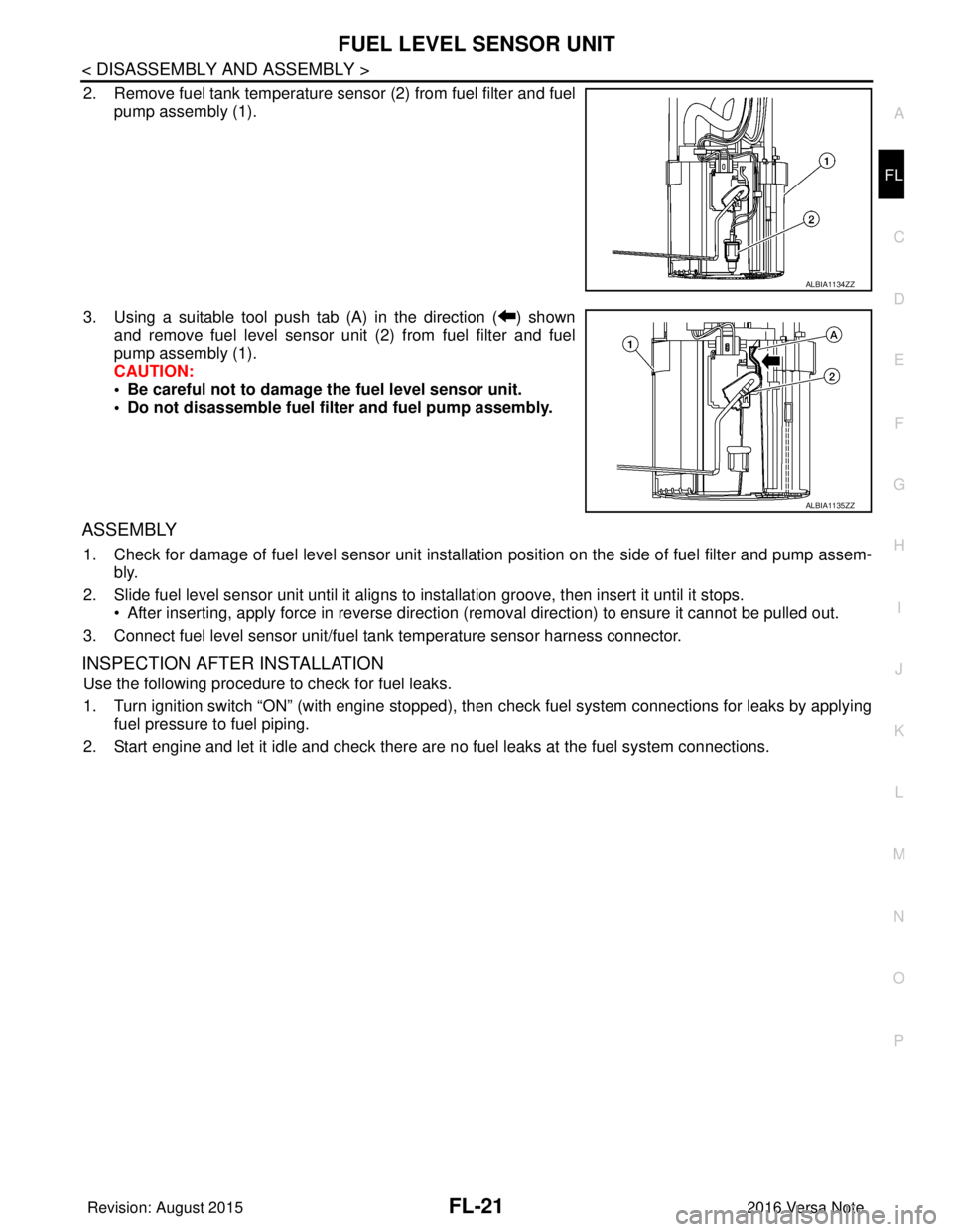
2. Remove fuel tank temperature s
ensor (2) from fuel filter and fuel
pump assembly (1).
3. Using a suitable tool push tab (A) in the direction ( ) shown and remove fuel level sensor unit (2) from fuel filter and fuel
pump assembly (1).
CAUTION:
• Be careful not to damage the fuel level sensor unit.
• Do not disassemble fuel filter and fuel pump assembly.
ASSEMBLY
1. Check for damage of fuel level sensor unit installation position on the side of fuel filter and pump assem- bly.
2. Slide fuel level sensor unit until it aligns to installation groove, then insert it until it stops. • After inserting, apply force in reverse direction (removal direction) to ensure it cannot be pulled out.
3. Connect fuel level sensor unit/fuel t ank temperature sensor harness connector.
INSPECTION AFTER INSTALLATION
Use the following procedure to check for fuel leaks.
1. Turn ignition switch “ON” (with engine stopped), then check fuel system connections for leaks by applying
fuel pressure to fuel piping.
2. Start engine and let it idle and check there are no fuel leaks at the fuel system connections.
ALBIA1134ZZ
ALBIA1135ZZ
Revision: August 2015 2016 Versa Note
cardiagn.com
Page 1894 of 3641
GI-6
< HOW TO USE THIS MANUAL >
HOW TO FOLLOW TROUBLE DIAGNOSES
HOW TO FOLLOW TROUBLE DIAGNOSES
DescriptionINFOID:0000000012433148
NOTICE:
Trouble diagnoses indicate work procedures required to diagnose problems effectively. Observe the following
instructions before diagnosing.
• Before performing trouble diagnoses, read the “Work Flow” in each section.
• After repairs, re-check that the problem has been completely eliminated.
• Refer to Component Parts and Harness Connector Location for the Systems described in each section for
identification/location of components and harness connectors.
• When checking circuit continuity, ignition switch should be OFF.
• Refer to the Circuit Diagram for quick pinpoint check. If you need to check circuit continui ty between harness connectors in more detail, such as when a sub-har-
ness is used, refer to Wiring Diagram in each individual section and Harness Layout in PG section for identi-
fication of harness connectors.
• Before checking voltage at connectors, check battery voltage.
• After accomplishing the Diagnosis Procedures and Elec trical Components Inspection, make sure that all
harness connectors are reconnected as they were.
How to Follow Test Grou ps in Trouble DiagnosisINFOID:0000000012433149
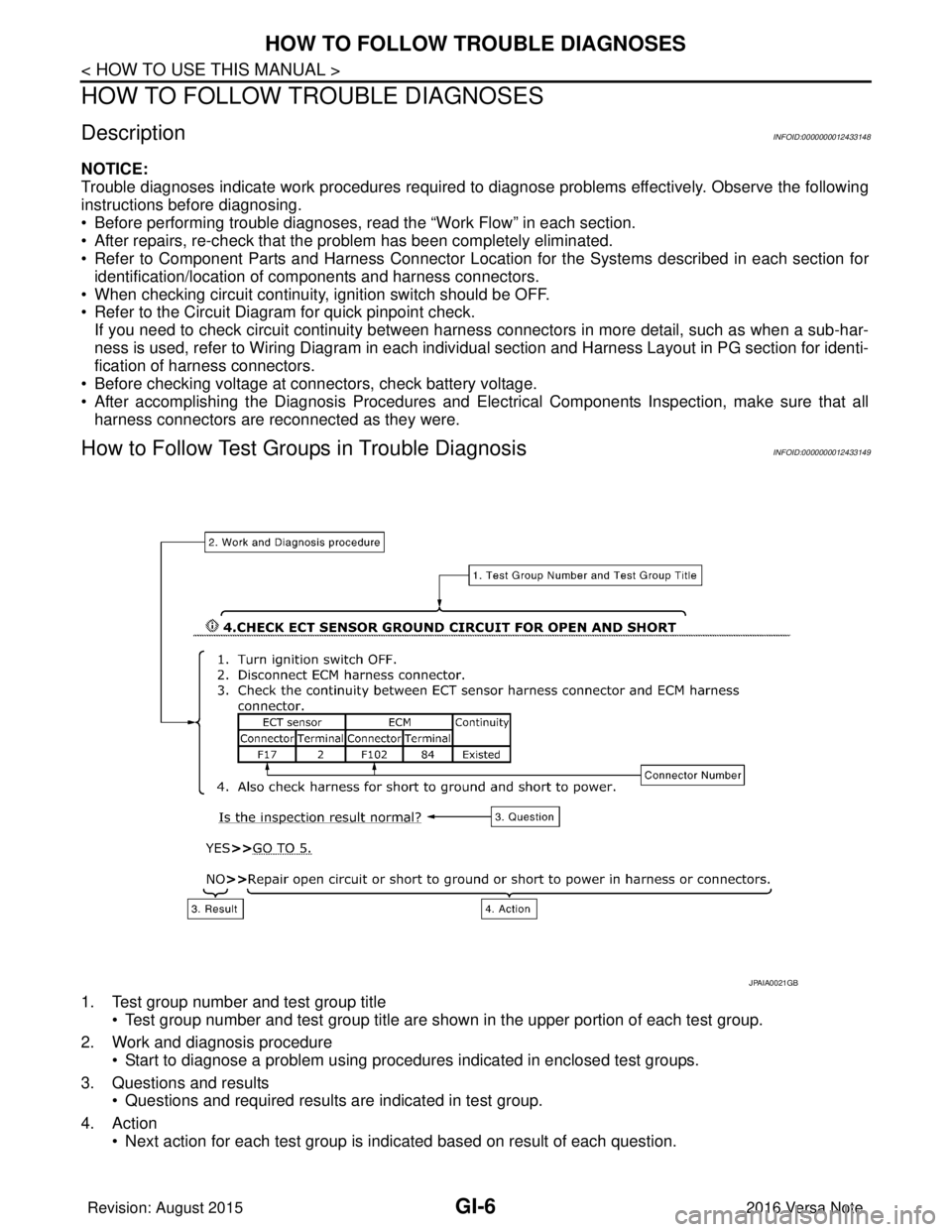
1. Test group number and test group title
• Test group number and test group title are s hown in the upper portion of each test group.
2. Work and diagnosis procedure • Start to diagnose a problem using procedures indicated in enclosed test groups.
3. Questions and results • Questions and required results are indicated in test group.
4. Action • Next action for each test group is indicated based on result of each question.
JPAIA0021GB
Revision: August 2015 2016 Versa Note
cardiagn.com
Page 1906 of 3641

GI-18
< HOW TO USE THIS MANUAL >
ABBREVIATIONS
U
V
W
1
2
3
4
5
6
7
ABBREVIATIONDESCRIPTION
USS Uphill start support
ABBREVIATION DESCRIPTION
VCM Vehicle control module
VDC Vehicle dynamics control system
VIN Vehicle identification number
VSS Vehicle speed sensor
ABBREVIATION DESCRIPTION
WOT Wide open throttle
ABBREVIATION DESCRIPTION
1
11st range first gear
1
21st range second gear
1GR First gear
ABBREVIATION DESCRIPTION
2
12nd range first gear
2
22nd range second gear
2GR Second gear
2WD 2-wheel drive
ABBREVIATION DESCRIPTION
3GR Third gear
ABBREVIATION DESCRIPTION
4GR Fourth gear
4WAS Four wheel active steer 4WD Four wheel drive
ABBREVIATION DESCRIPTION
5GR Fifth gear
ABBREVIATION DESCRIPTION
6GR Sixth gear
ABBREVIATION DESCRIPTION
7GR Seventh gear
Revision: August 2015 2016 Versa Note
cardiagn.com
Page 1912 of 3641
GI-24
< PRECAUTION >
PRECAUTIONS
General Precautions
INFOID:0000000012433162
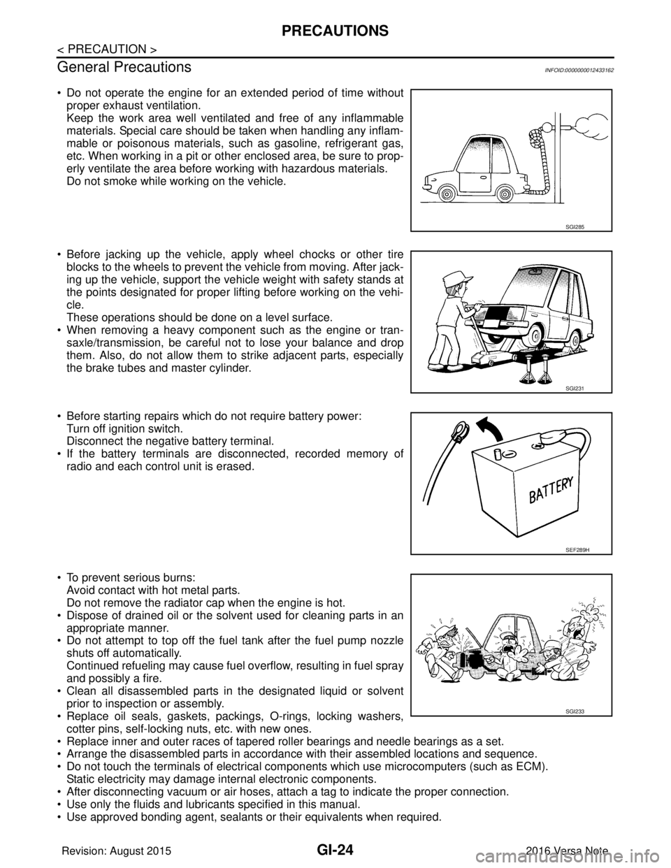
• Do not operate the engine for an extended period of time without proper exhaust ventilation.
Keep the work area well ventilated and free of any inflammable
materials. Special care should be taken when handling any inflam-
mable or poisonous materials, such as gasoline, refrigerant gas,
etc. When working in a pit or other enclosed area, be sure to prop-
erly ventilate the area before working with hazardous materials.
Do not smoke while working on the vehicle.
• Before jacking up the vehicle, apply wheel chocks or other tire blocks to the wheels to prevent the vehicle from moving. After jack-
ing up the vehicle, support the vehicle weight with safety stands at
the points designated for proper lifting before working on the vehi-
cle.
These operations should be done on a level surface.
• When removing a heavy component such as the engine or tran- saxle/transmission, be careful not to lose your balance and drop
them. Also, do not allow them to strike adjacent parts, especially
the brake tubes and master cylinder.
• Before starting repairs which do not require battery power: Turn off ignition switch.
Disconnect the negative battery terminal.
• If the battery terminals are disconnected, recorded memory of radio and each control unit is erased.
• To prevent serious burns: Avoid contact with hot metal parts.
Do not remove the radiator cap when the engine is hot.
• Dispose of drained oil or the solvent used for cleaning parts in an appropriate manner.
• Do not attempt to top off the fuel tank after the fuel pump nozzle
shuts off automatically.
Continued refueling may cause fuel overflow, resulting in fuel spray
and possibly a fire.
• Clean all disassembled parts in the designated liquid or solvent prior to inspection or assembly.
• Replace oil seals, gaskets, packings, O-rings, locking washers,
cotter pins, self-locking nuts, etc. with new ones.
• Replace inner and outer races of tapered roller bearings and needle bearings as a set.
• Arrange the disassembled parts in accordance with their assembled locations and sequence.
• Do not touch the terminals of electrical com ponents which use microcomputers (such as ECM).
Static electricity may damage internal electronic components.
• After disconnecting vacuum or air hoses, atta ch a tag to indicate the proper connection.
• Use only the fluids and lubricants specified in this manual.
• Use approved bonding agent, sealants or their equivalents when required.
SGI285
SGI231
SEF289H
SGI233
Revision: August 2015 2016 Versa Note
cardiagn.com
Page 1930 of 3641
GI-42
< BASIC INSPECTION >
SERVICE INFORMATION FOR ELECTRICAL INCIDENT
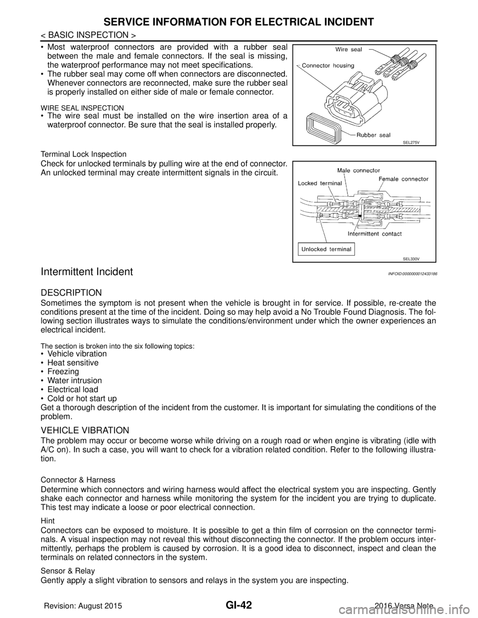
• Most waterproof connectors are provided with a rubber sealbetween the male and female connectors. If the seal is missing,
the waterproof performance may not meet specifications.
• The rubber seal may come off when connectors are disconnected. Whenever connectors are reconnected, make sure the rubber seal
is properly installed on either side of male or female connector.
WIRE SEAL INSPECTION
• The wire seal must be installed on the wire insertion area of awaterproof connector. Be sure that the seal is installed properly.
Terminal Lock Inspection
Check for unlocked terminals by pulling wire at the end of connector.
An unlocked terminal may create intermittent signals in the circuit.
Intermittent IncidentINFOID:0000000012433186
DESCRIPTION
Sometimes the symptom is not present when the vehicle is brought in for service. If possible, re-create the
conditions present at the time of the incident. Doi ng so may help avoid a No Trouble Found Diagnosis. The fol-
lowing section illustrates ways to simulate the condi tions/environment under which the owner experiences an
electrical incident.
The section is broken into the six following topics:
• Vehicle vibration
• Heat sensitive
• Freezing
• Water intrusion
• Electrical load
• Cold or hot start up
Get a thorough description of the incident from the customer. It is important for simulating the conditions of the
problem.
VEHICLE VIBRATION
The problem may occur or become worse while driving on a rough road or when engine is vibrating (idle with
A/C on). In such a case, you will want to check for a vi bration related condition. Refer to the following illustra-
tion.
Connector & Harness
Determine which connectors and wiring harness would affect the electrical system you are inspecting. Gently
shake each connector and harness while monitoring the sy stem for the incident you are trying to duplicate.
This test may indicate a loose or poor electrical connection.
Hint
Connectors can be exposed to moisture. It is possible to get a thin film of corrosion on the connector termi-
nals. A visual inspection may not reveal this without disconnecting the connector. If the problem occurs inter-
mittently, perhaps the problem is caused by corrosion. It is a good idea to disconnect, inspect and clean the
terminals on related connectors in the system.
Sensor & Relay
Gently apply a slight vibration to sensors and relays in the system you are inspecting.
SEL275V
SEL330V
Revision: August 2015 2016 Versa Note
cardiagn.com
Page 1931 of 3641
SERVICE INFORMATION FOR ELECTRICAL INCIDENTGI-43
< BASIC INSPECTION >
C
DE
F
G H
I
J
K L
M B
GI
N
O P
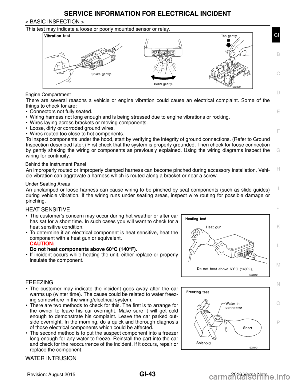
This test may indicate a loose or poorly mounted sensor or relay.
Engine Compartment
There are several reasons a vehicle or engine vibration could cause an electrical complaint. Some of the
things to check for are:
• Connectors not fully seated.
• Wiring harness not long enough and is being stressed due to engine vibrations or rocking.
• Wires laying across brackets or moving components.
• Loose, dirty or corroded ground wires.
• Wires routed too close to hot components.
To inspect components under the hood, start by verifyi ng the integrity of ground connections. (Refer to Ground
Inspection described later.) First check that the system is properly grounded. Then check for loose connection
by gently shaking the wiring or components as previous ly explained. Using the wiring diagrams inspect the
wiring for continuity.
Behind the Instrument Panel
An improperly routed or improperly clamped harness can become pinched during accessory installation. Vehi-
cle vibration can aggravate a harness which is routed along a bracket or near a screw.
Under Seating Areas
An unclamped or loose harness can cause wiring to be pinched by seat components (such as slide guides)
during vehicle vibration. If the wiring runs under s eating areas, inspect wire routing for possible damage or
pinching.
HEAT SENSITIVE
• The customer's concern may occur during hot weather or after car has sat for a short time. In such cases you will want to check for a
heat sensitive condition.
• To determine if an electrical component is heat sensitive, heat the component with a heat gun or equivalent.
CAUTION:
Do not heat components above 60 °C (140° F).
• If incident occurs while heating t he unit, either replace or properly
insulate the component.
FREEZING
• The customer may indicate the incident goes away after the car warms up (winter time). The cause could be related to water freez-
ing somewhere in the wiring/electrical system.
• There are two methods to check for this. The first is to arrange for the owner to leave his car overnight. Make sure it will get cold
enough to demonstrate his complaint. Leave the car parked out-
side overnight. In the morning, do a quick and thorough diagnosis
of those electrical components which could be affected.
• The second method is to put the suspect component into a freezer long enough for any water to freeze. Reinstall the part into the car
and check for the reoccurrence of the incident. If it occurs, repair or
replace the component.
WATER INTRUSION
SGI839
SGI842
SGI843
Revision: August 2015 2016 Versa Note
cardiagn.com
Page 1932 of 3641
GI-44
< BASIC INSPECTION >
SERVICE INFORMATION FOR ELECTRICAL INCIDENT
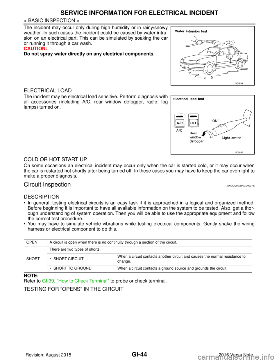
The incident may occur only during high humidity or in rainy/snowy
weather. In such cases the incident could be caused by water intru-
sion on an electrical part. This can be simulated by soaking the car
or running it through a car wash.
CAUTION:
Do not spray water directly on any electrical components.
ELECTRICAL LOAD
The incident may be electrical load sensitive. Perform diagnosis with
all accessories (including A/C, rear window defogger, radio, fog
lamps) turned on.
COLD OR HOT START UP
On some occasions an electrical incident may occur only when the car is started cold, or it may occur when
the car is restarted hot shortly after being turned off. In these cases you may have to keep the car overnight to
make a proper diagnosis.
Circuit InspectionINFOID:0000000012433187
DESCRIPTION
• In general, testing electrical circuits is an easy task if it is approached in a logical and organized method.
Before beginning it is important to have all available information on the system to be tested. Also, get a thor-
ough understanding of system operation. Then you will be able to use the appropriate equipment and follow
the correct test procedure.
• You may have to simulate vehicle vibrations while te sting electrical components. Gently shake the wiring
harness or electrical component to do this.
NOTE:
Refer to GI-39, "
How to Check Terminal" to probe or check terminal.
TESTING FOR “OPENS” IN THE CIRCUIT
SGI844
SGI845
OPEN A circuit is open when there is no continuity through a section of the circuit.
SHORT There are two types of shorts.
• SHORT CIRCUIT
When a circuit contacts another circuit and causes the normal resistance to
change.
• SHORT TO GROUND When a circuit contacts a ground source and grounds the circuit.
Revision: August 2015 2016 Versa Note
cardiagn.com