2016 NISSAN NOTE start
[x] Cancel search: startPage 1673 of 3641
DIAGNOSIS SYSTEM (IPDM E/R)EXL-21
< SYSTEM DESCRIPTION >
C
DE
F
G H
I
J
K
M A
B
EXL
N
O P
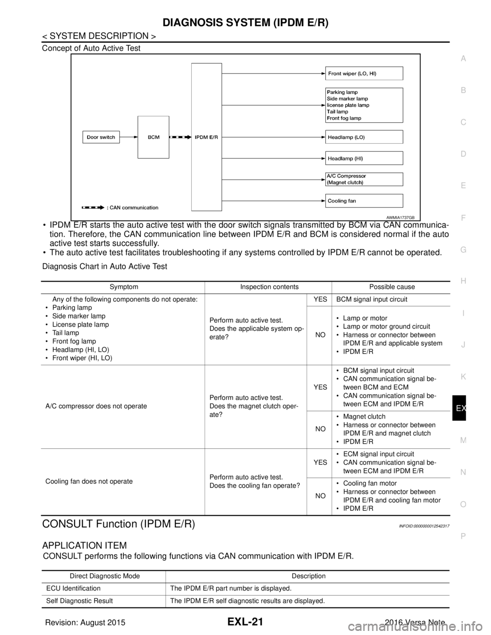
Concept of Auto Active Test
• IPDM E/R starts the auto active test with the door
switch signals transmitted by BCM via CAN communica-
tion. Therefore, the CAN communication line between IPDM E/R and BCM is considered normal if the auto
active test starts successfully.
• The auto active test facilitates troubleshooting if any systems controlled by IPDM E/R cannot be operated.
Diagnosis Chart in Auto Active Test
CONSULT Function (IPDM E/R)INFOID:0000000012542317
APPLICATION ITEM
CONSULT performs the following functions via CAN communication with IPDM E/R.
AWMIA1737GB
SymptomInspection contentsPossible cause
Any of the following components do not operate:
•Parking lamp
• Side marker lamp
• License plate lamp
•Tail lamp
•Front fog lamp
• Headlamp (HI, LO)
• Front wiper (HI, LO) Perform auto active test.
Does the applicable system op-
erate?YES BCM signal input circuit
NO • Lamp or motor
• Lamp or motor ground circuit
• Harness or connector between
IPDM E/R and applicable system
•IPDM E/R
A/C compressor does not operate Perform auto active test.
Does the magnet clutch oper-
ate?YES
• BCM signal input circuit
• CAN communication signal be-
tween BCM and ECM
• CAN communication signal be-
tween ECM and IPDM E/R
NO • Magnet clutch
• Harness or connector between
IPDM E/R and magnet clutch
•IPDM E/R
Cooling fan does not operate Perform auto active test.
Does the cooling fan operate?YES
• ECM signal input circuit
• CAN communication signal be-
tween ECM and IPDM E/R
NO • Cooling fan motor
• Harness or connector between
IPDM E/R and cooling fan motor
•IPDM E/R
Direct Diagnostic Mode Description
ECU Identification The IPDM E/R part number is displayed.
Self Diagnostic Result The IPDM E/R self diagnostic results are displayed.
Revision: August 2015 2016 Versa Note
cardiagn.com
Page 1674 of 3641

EXL-22
< SYSTEM DESCRIPTION >
DIAGNOSIS SYSTEM (IPDM E/R)
ECU IDENTIFICATION
The IPDM E/R part number is displayed.
SELF DIAGNOSTIC RESULT
Refer to PCS-20, "DTCIndex".
DATA MONITOR
ACTIVE TEST
Data Monitor The IPDM E/R input/output data is displayed in real time.
Active Test The IPDM E/R activates outputs to test components.
CAN Diag Support Mntr The result of transmit/receive diagnosis of CAN communication is displayed.
Direct Diagnostic Mode
Description
Monitor Item [Unit]Main
Signals Description
MOTOR FAN REQ [1/2/3/4] ×Indicates cooling fan speed signal received from ECM on CAN communication
line
AC COMP REQ [On/Off] ×Indicates A/C compressor request signal received from ECM on CAN commu-
nication line
TAIL&CLR REQ [On/Off] ×Indicates position light request signal received from BCM on CAN communica-
tion line
HL LO REQ [On/Off] ×Indicates low beam request signal received from BCM on CAN communication
line
HL HI REQ [On/Off] ×Indicates high beam request signal received from BCM on CAN communication
line
FR FOG REQ [On/Off] ×Indicates front fog light request signal received from BCM on CAN communica-
tion line
FR WIP REQ [Stop/1LOW/Low/Hi] ×Indicates front wiper request signal received from BCM on CAN communication
line
WIP AUTO STOP [STOP P/ACT P] ×Indicates condition of front wiper auto stop signal
WIP PROT [Off/BLOCK] ×Indicates condition of front wiper fail-safe operation
IGN RLY1 -REQ [On/Off] Indicates ignition switch ON signal received from BCM on CAN communication
line
IGN RLY [On/Off] ×Indicates condition of ignition relay
PUSH SW [On/Off] Indicates condition of push-button ignition switch
INTER/NP SW [On/Off] Indicates condition of CVT shift position
ST RLY CONT [On/Off] Indicates starter relay status signal received from BCM on CAN communication
line
IHBT RLY -REQ [On/Off] Indicates starter control relay signal received from BCM on CAN communication
line
ST/INHI RLY [Off/ ST /INHI] Indicates condition of starter relay and starter control relay
DETENT SW [On/Off] Indicates condition of CVT shift selector (park position switch)
DTRL REQ [Off] Indicates daytime running light request signal received from BCM on CAN com-
munication line
THFT HRN REQ [On/Off] Indicates theft warning horn request signal received from BCM on CAN commu-
nication line
HORN CHIRP [On/Off] Indicates horn reminder signal received from BCM on CAN communication line
Te s t i t e m D e s c r i p t i o n
HORN This test is able to check horn operation [On].
FRONT WIPER This test is able to check wiper motor operation [Hi/Lo/Off].
Revision: August 2015 2016 Versa Note
cardiagn.com
Page 1727 of 3641

POWER SUPPLY AND GROUND CIRCUITEXL-75
< DTC/CIRCUIT DIAGNOSIS >
C
DE
F
G H
I
J
K
M A
B
EXL
N
O P
1.CHECK FUSES AND FUSIBLE LINK
Check that the following fuses and fusible link are not blown.
Is the fuse blown?
YES >> Replace the blown fuse or fusible link after repairing the affected circuit.
NO >> GO TO 2.
2.CHECK POWER SUPPLY CIRCUIT
1. Turn ignition switch OFF.
2. Disconnect BCM connectors.
3. Check voltage between BCM connector and ground.
Is the inspection result normal?
YES >> GO TO 3.
NO >> Repair harness or connector.
3.CHECK GROUND CIRCUIT
Check continuity between BCM connector and ground.
Is the inspection result normal?
YES >> Inspection End.
NO >> Repair harness or connector.
IPDM E/R
IPDM E/R : Diagnosis ProcedureINFOID:0000000012542320
Regarding Wiring Diagram information, refer to PCS-21, "Wiring Diagram".
1. CHECK FUSE AND FUSIBLE LINKS
Check that the following IPDM E/R fuse or fusible links are not blown.
Terminal No. Signal nameFuses and fusible link No.
37 Battery power supply 8 (10A)
42 12 (10A)
50 G (40A)
11 Ignition switch ACC or ON 18 (10A)
38 Ignition switch ON or START 2 (10A)
BCMGround Ignition switch position
Connector Terminal
—OFF
ACC ON
M18 11
0 V
Battery voltage
Battery voltage
37
Battery voltage
38 0 V0 V
M19 42
Battery voltage Battery voltage
50
BCM GroundContinuity
Connector Terminal
M19 55—Yes
Revision: August 2015 2016 Versa Note
cardiagn.com
Page 1729 of 3641
HEADLAMP (HI) CIRCUITEXL-77
< DTC/CIRCUIT DIAGNOSIS >
C
DE
F
G H
I
J
K
M A
B
EXL
N
O P
HEADLAMP (HI) CIRCUIT
DescriptionINFOID:0000000012432804
The IPDM E/R (intelligent power distribution modul e engine room) controls the headlamp high relay based on
inputs from the BCM via the CAN communication lines. When the headlamp high relay is energized, power
flows through fuses 34 and 35, located in the IPDM E/R. Power then flows to the front combination lamp LH
and RH high beams.
Component Function CheckINFOID:0000000012432805
1.CHECK HEADLAMP (HI) OPERATION
WITHOUT CONSULT
1. Start IPDM E/R auto active test. Refer to PCS-9, "
Diagnosis Description".
2. Check that the headlamp switches to the high beam.
CONSULT
1. Select EXTERNAL LAMPS of IP DM E/R active test item.
2. While operating the test items, check that the headlamp switches to the high beam.
Does the headlamp switch to high beam?
YES >> Headlamp (HI) circuit is normal.
NO >> Refer to EXL-77, "
Diagnosis Procedure".
Diagnosis ProcedureINFOID:0000000012432806
Regarding Wiring Diagram information, refer to EXL-25, "Wiring Diagram - For USA" or EXL-31, "Wiring Dia-
gram - For Canada".
1.CHECK HEADLAMP (HI) FUSES
1. Turn the ignition switch OFF.
2. Check that the following fuses are not blown:
Is the fuse blown?
YES >> Replace the blown fuse after repairing the affected circuit.
NO >> GO TO 2.
2.CHECK HIGH BEAM BULB
Check the applicable high beam bulb to be sure the proper bulb standard is in use and the bulb is not open.
Is the bulb OK?
YES >> GO TO 3.
NO >> Replace the bulb.
3.CHECK HEADLAMP (HI) OUTPUT VOLTAGE
1. Turn the ignition switch OFF.
2. Disconnect the front combination lamp connector E25 or E26.
3. Turn the ignition switch ON.
4. Turn the high beam headlamps ON.
5. With the high beam headlamps ON, check the vo ltage between the combination lamp connector and
ground. HI : Headlamp switches to the high beam.
OFF : Headlamp OFF
Unit
LocationFuse No.Capacity
Headlamp HI (LH) IPDM E/R3510A
Headlamp HI (RH) IPDM E/R3410A
Revision: August 2015 2016 Versa Note
cardiagn.com
Page 1731 of 3641
HEADLAMP (LO) CIRCUITEXL-79
< DTC/CIRCUIT DIAGNOSIS >
C
DE
F
G H
I
J
K
M A
B
EXL
N
O P
HEADLAMP (LO) CIRCUIT
DescriptionINFOID:0000000012432807
The IPDM E/R (intelligent power distribution modul e engine room) controls the headlamp low relay based on
inputs from the BCM via the CAN communication li nes. When the headlamp low relay is energized, power
flows through fuses 40 and 41, located in the IPDM E/R.
(Without daytime running light system) power then flow s to the front combination lamp LH and RH low beams.
(With daytime running light system) power then flows to the front combination lamp LH low beam and the day-
time running light relay 2 which becomes energized and t hen power is sent to the front combination lamp RH
low beam.
Component Function CheckINFOID:0000000012432808
1.CHECK HEADLAMP (LO) OPERATION
WITHOUT CONSULT
1. Start IPDM E/R auto active test. Refer to PCS-9, "
Diagnosis Description".
2. Check that the headlamp is turned ON.
CONSULT
1. Select EXTERNAL LAMPS of IP DM E/R active test item.
2. While operating the test items, check that the headlamp is turned ON.
Is the headlamp turned ON?
YES >> Headlamp (LO) is normal.
NO >> Refer to EXL-79, "
Diagnosis Procedure".
Diagnosis ProcedureINFOID:0000000012432809
Regarding Wiring Diagram information, refer to EXL-25, "Wiring Diagram - For USA" or EXL-31, "Wiring Dia-
gram - For Canada".
1.CHECK HEADLAMP (LO) FUSES
1. Turn the ignition switch OFF.
2. Check that the following fuses are not blown:
Is the fuse blown?
YES >> Replace the blown fuse after repairing the affected circuit.
NO >> GO TO 2.
2.CHECK LOW BEAM BULB
Check the applicable low beam bulb to be sure the proper bulb standard is in use and the bulb is not open.
Is the bulb OK?
YES >> GO TO 3.
NO >> Replace the bulb.
3.CHECK HEADLAMP (LO) OUTPUT VOLTAGE
1. Turn the ignition switch OFF.
2. Disconnect the front combination lamp connector E25 or E26.
3. Turn the ignition switch ON. LO : Headlamp ON
OFF : Headlamp OFF
Unit
LocationFuse No.Capacity
Headlamp LO (L H) IPDM E/R 4115A
Headlamp LO (RH) IPDM E/R4015A
Revision: August 2015 2016 Versa Note
cardiagn.com
Page 1734 of 3641
EXL-82
< DTC/CIRCUIT DIAGNOSIS >
PARKING LAMP CIRCUIT
PARKING LAMP CIRCUIT
DescriptionINFOID:0000000012432810
The IPDM E/R (intelligent power distribution module engine room) controls the tail lamp relay based on inputs
from the BCM via the CAN communication lines. When the tail lamp relay is energized, power flows through
fuse 37, located in the IPDM E/R. Power then flows through the tail lamp relay to the front and rear combina-
tion lamps, license plate lamps.
Component Function CheckINFOID:0000000012432811
1.CHECK PARKING LAMP OPERATION
WITHOUT CONSULT
1. Start IPDM E/R auto active test. Refer to PCS-9, "
Diagnosis Description".
2. Check that the parking lamps are turned ON.
CONSULT
1. Select EXTERNAL LAMPS of IPDM E/R active test item.
2. While operating the test items, check that the parking lamps are turned ON.
Is the parking lamp turned ON?
YES >> Parking lamp circuit is normal.
NO >> Refer to EXL-82, "
Diagnosis Procedure".
Diagnosis ProcedureINFOID:0000000012432812
Regarding Wiring Diagram information, refer to EXL-55, "Wiring Diagram".
1.CHECK PARKING LAMP FUSES
1. Turn the ignition switch OFF.
2. Check that the following fuses are not blown:
Is the fuse blown?
YES >> Replace the blown fuse after repairing the affected circuit.
NO >> GO TO 2.
2.CHECK PARKING LAMP BULB
Check the applicable lamp bulb to be sure the proper bulb standard is in use and the bulb is not open.
Is the bulb OK?
YES >> GO TO 3.
NO >> Replace the bulb.
3.CHECK TAIL LAMP RELAY OUTPUT (VOLTAGE)
1. Turn the ignition switch OFF.
2. Disconnect the front combination lamp connector, rear combination lamp connector and license plate
lamp connector.
3. Turn the ignition switch ON.
4. Turn the parking lamps ON.
5. With the parking lamps ON, check voltage between the front combination lamp connectors and ground. TAIL : Parking lamp ON
OFF : Parking lamp OFF
Unit
LocationFuse No.Capacity
Parking lamps IPDM E/R3710A
Revision: August 2015 2016 Versa Note
cardiagn.com
Page 1740 of 3641
EXL-88
< DTC/CIRCUIT DIAGNOSIS >
FRONT FOG LAMP CIRCUIT
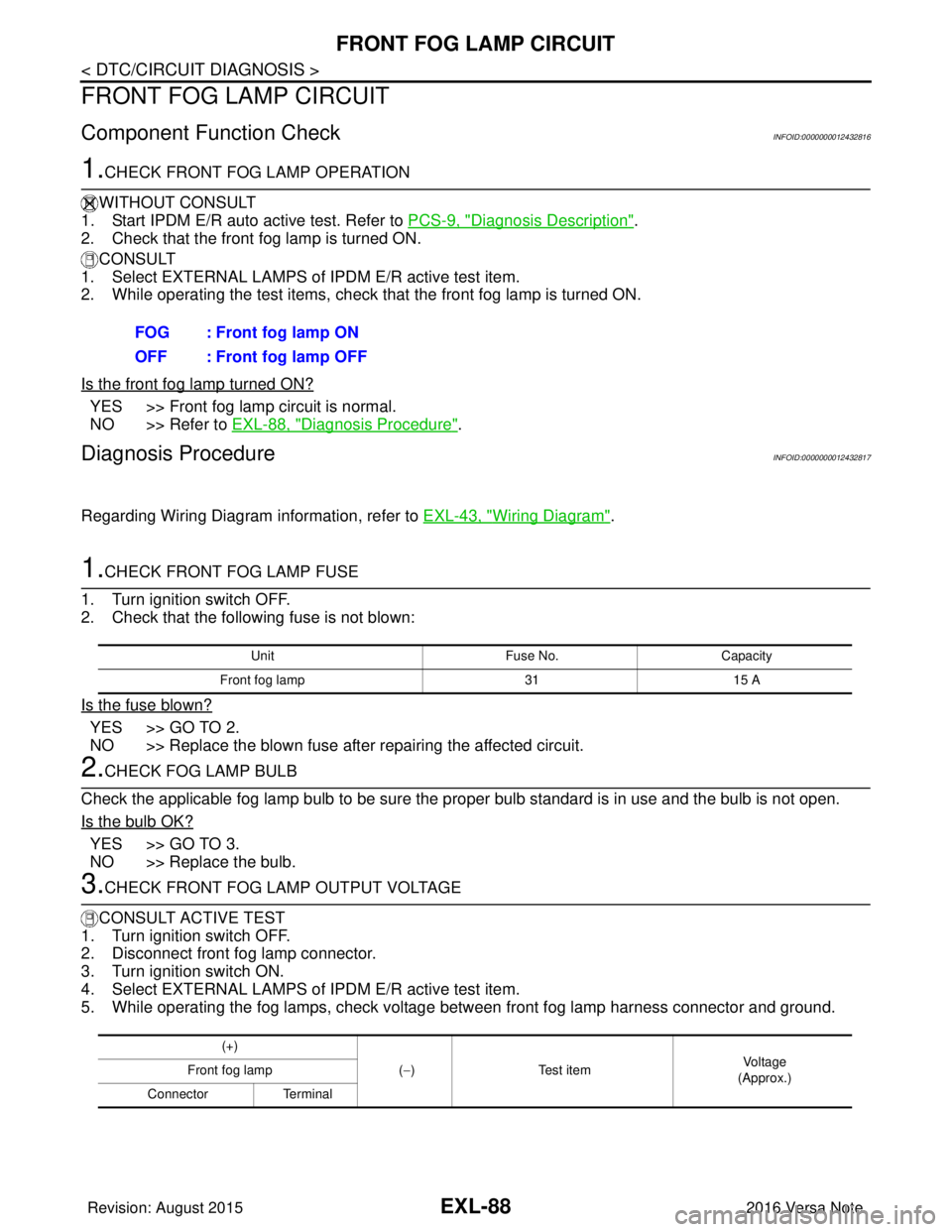
FRONT FOG LAMP CIRCUIT
Component Function CheckINFOID:0000000012432816
1.CHECK FRONT FOG LAMP OPERATION
WITHOUT CONSULT
1. Start IPDM E/R auto active test. Refer to PCS-9, "
Diagnosis Description".
2. Check that the front fog lamp is turned ON.
CONSULT
1. Select EXTERNAL LAMPS of IPDM E/R active test item.
2. While operating the test items, check that the front fog lamp is turned ON.
Is the front fog lamp turned ON?
YES >> Front fog lamp circuit is normal.
NO >> Refer to EXL-88, "
Diagnosis Procedure".
Diagnosis ProcedureINFOID:0000000012432817
Regarding Wiring Diagram information, refer to EXL-43, "Wiring Diagram".
1.CHECK FRONT FOG LAMP FUSE
1. Turn ignition switch OFF.
2. Check that the following fuse is not blown:
Is the fuse blown?
YES >> GO TO 2.
NO >> Replace the blown fuse after repairing the affected circuit.
2.CHECK FOG LAMP BULB
Check the applicable fog lamp bulb to be sure the proper bulb standard is in use and the bulb is not open.
Is the bulb OK?
YES >> GO TO 3.
NO >> Replace the bulb.
3.CHECK FRONT FOG LAMP OUTPUT VOLTAGE
CONSULT ACTIVE TEST
1. Turn ignition switch OFF.
2. Disconnect front fog lamp connector.
3. Turn ignition switch ON.
4. Select EXTERNAL LAMPS of IPDM E/R active test item.
5. While operating the fog lamps, check voltage between front fog lamp harness connector and ground.
FOG : Front fog lamp ON
OFF : Front fog lamp OFF
Unit
Fuse No.Capacity
Front fog lamp 3115 A
(+)
(−) Test item Vo l ta g e
(Approx.)
Front fog lamp
Connector Terminal
Revision: August 2015 2016 Versa Note
cardiagn.com
Page 1750 of 3641
EXL-98
< PERIODIC MAINTENANCE >
HEADLAMP AIMING ADJUSTMENT
Aiming Adjustment Procedure
INFOID:0000000012432829
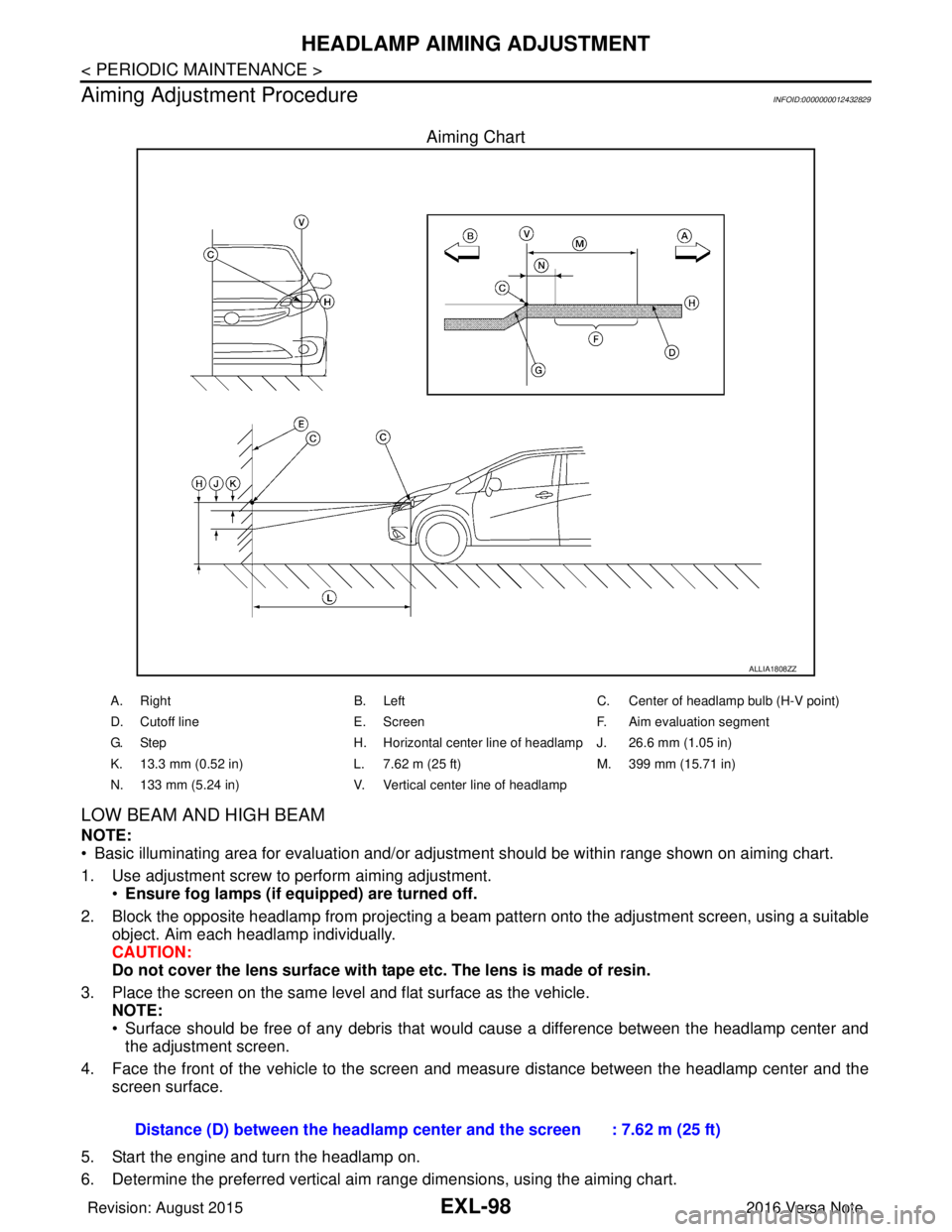
Aiming Chart
LOW BEAM AND HIGH BEAM
NOTE:
• Basic illuminating area for evaluation and/or adjus tment should be within range shown on aiming chart.
1. Use adjustment screw to perform aiming adjustment. •Ensure fog lamps (if eq uipped) are turned off.
2. Block the opposite headlamp from projecting a beam pa ttern onto the adjustment screen, using a suitable
object. Aim each headlamp individually.
CAUTION:
Do not cover the lens surface with tape etc. The lens is made of resin.
3. Place the screen on the same level and flat surface as the vehicle. NOTE:
• Surface should be free of any debris that would cause a difference between the headlamp center and
the adjustment screen.
4. Face the front of the vehicle to the screen and measure distance between the headlamp center and the screen surface.
5. Start the engine and turn the headlamp on.
6. Determine the preferred vertical aim range dimensions, using the aiming chart.
ALLIA1808ZZ
A. Right B. LeftC. Center of headlamp bulb (H-V point)
D. Cutoff line E. ScreenF. Aim evaluation segment
G. Step H. Horizontal center line of headlamp J. 26.6 mm (1.05 in)
K. 13.3 mm (0.52 in) L. 7.62 m (25 ft)M. 399 mm (15.71 in)
N. 133 mm (5.24 in) V. Vertical center line of headlamp
Distance (D) between the headlamp center and the screen : 7.62 m (25 ft)
Revision: August 2015 2016 Versa Note
cardiagn.com