2016 NISSAN NOTE start
[x] Cancel search: startPage 2285 of 3641
![NISSAN NOTE 2016 Service Repair Manual LAN
CAN COMMUNICATION CIRCUITLAN-97
< DTC/CIRCUIT DIAGNOSIS > [CAN SYSTEM (TYPE 503)]
C
D
E
F
G H
I
J
K L
B A
O P
N
Inspection result
Reproduced>>GO TO 6.
Non-reproduced>>Start the diagnosis again. Fo NISSAN NOTE 2016 Service Repair Manual LAN
CAN COMMUNICATION CIRCUITLAN-97
< DTC/CIRCUIT DIAGNOSIS > [CAN SYSTEM (TYPE 503)]
C
D
E
F
G H
I
J
K L
B A
O P
N
Inspection result
Reproduced>>GO TO 6.
Non-reproduced>>Start the diagnosis again. Fo](/manual-img/5/57363/w960_57363-2284.png)
LAN
CAN COMMUNICATION CIRCUITLAN-97
< DTC/CIRCUIT DIAGNOSIS > [CAN SYSTEM (TYPE 503)]
C
D
E
F
G H
I
J
K L
B A
O P
N
Inspection result
Reproduced>>GO TO 6.
Non-reproduced>>Start the diagnosis again. Follow the trouble diagnosis procedure when past error is
detected.
6.CHECK UNIT REPRODUCTION
Perform the reproduction test as per the following procedure for each unit.
1. Turn the ignition switch OFF.
2. Disconnect the battery cabl e from the negative terminal.
3. Disconnect one of the unit connectors of CAN communication system.
NOTE:
ECM and BCM have a termination circuit. Check other units first.
4. Connect the battery cable to the negative terminal. Check if the symptoms described in the “Symptom
(Results from interview with customer)” are reproduced.
NOTE:
Although unit-related error symptoms occur, do not confuse them with other symptoms.
Inspection result
Reproduced>>Connect the connector. Check other units as per the above procedure.
Non-reproduced>>Replace the unit whose connector was disconnected.
Revision: August 2015 2016 Versa Note
cardiagn.com
Page 2301 of 3641
![NISSAN NOTE 2016 Service Repair Manual LAN
CAN COMMUNICATION CIRCUITLAN-113
< DTC/CIRCUIT DIAGNOSIS > [CAN SYSTEM (TYPE 504)]
C
D
E
F
G H
I
J
K L
B A
O P
N
Inspection result
Reproduced>>GO TO 6.
Non-reproduced>>Start the diagnosis again. F NISSAN NOTE 2016 Service Repair Manual LAN
CAN COMMUNICATION CIRCUITLAN-113
< DTC/CIRCUIT DIAGNOSIS > [CAN SYSTEM (TYPE 504)]
C
D
E
F
G H
I
J
K L
B A
O P
N
Inspection result
Reproduced>>GO TO 6.
Non-reproduced>>Start the diagnosis again. F](/manual-img/5/57363/w960_57363-2300.png)
LAN
CAN COMMUNICATION CIRCUITLAN-113
< DTC/CIRCUIT DIAGNOSIS > [CAN SYSTEM (TYPE 504)]
C
D
E
F
G H
I
J
K L
B A
O P
N
Inspection result
Reproduced>>GO TO 6.
Non-reproduced>>Start the diagnosis again. Follow the trouble diagnosis procedure when past error is
detected.
6.CHECK UNIT REPRODUCTION
Perform the reproduction test as per the following procedure for each unit.
1. Turn the ignition switch OFF.
2. Disconnect the battery cabl e from the negative terminal.
3. Disconnect one of the unit connectors of CAN communication system.
NOTE:
ECM and BCM have a termination circuit. Check other units first.
4. Connect the battery cable to the negative terminal. Check if the symptoms described in the “Symptom
(Results from interview with customer)” are reproduced.
NOTE:
Although unit-related error symptoms occur, do not confuse them with other symptoms.
Inspection result
Reproduced>>Connect the connector. Check other units as per the above procedure.
Non-reproduced>>Replace the unit whose connector was disconnected.
Revision: August 2015 2016 Versa Note
cardiagn.com
Page 2315 of 3641
![NISSAN NOTE 2016 Service Repair Manual LAN
CAN COMMUNICATION CIRCUITLAN-127
< DTC/CIRCUIT DIAGNOSIS > [CAN SYSTEM (TYPE 505)]
C
D
E
F
G H
I
J
K L
B A
O P
N
Inspection result
Reproduced>>GO TO 6.
Non-reproduced>>Start the diagnosis again. F NISSAN NOTE 2016 Service Repair Manual LAN
CAN COMMUNICATION CIRCUITLAN-127
< DTC/CIRCUIT DIAGNOSIS > [CAN SYSTEM (TYPE 505)]
C
D
E
F
G H
I
J
K L
B A
O P
N
Inspection result
Reproduced>>GO TO 6.
Non-reproduced>>Start the diagnosis again. F](/manual-img/5/57363/w960_57363-2314.png)
LAN
CAN COMMUNICATION CIRCUITLAN-127
< DTC/CIRCUIT DIAGNOSIS > [CAN SYSTEM (TYPE 505)]
C
D
E
F
G H
I
J
K L
B A
O P
N
Inspection result
Reproduced>>GO TO 6.
Non-reproduced>>Start the diagnosis again. Follow the trouble diagnosis procedure when past error is
detected.
6.CHECK UNIT REPRODUCTION
Perform the reproduction test as per the following procedure for each unit.
1. Turn the ignition switch OFF.
2. Disconnect the battery cabl e from the negative terminal.
3. Disconnect one of the unit connectors of CAN communication system.
NOTE:
ECM and BCM have a termination circuit. Check other units first.
4. Connect the battery cable to the negative terminal. Check if the symptoms described in the “Symptom
(Results from interview with customer)” are reproduced.
NOTE:
Although unit-related error symptoms occur, do not confuse them with other symptoms.
Inspection result
Reproduced>>Connect the connector. Check other units as per the above procedure.
Non-reproduced>>Replace the unit whose connector was disconnected.
Revision: August 2015 2016 Versa Note
cardiagn.com
Page 2335 of 3641
MA-20
< PERIODIC MAINTENANCE >
ENGINE MAINTENANCE
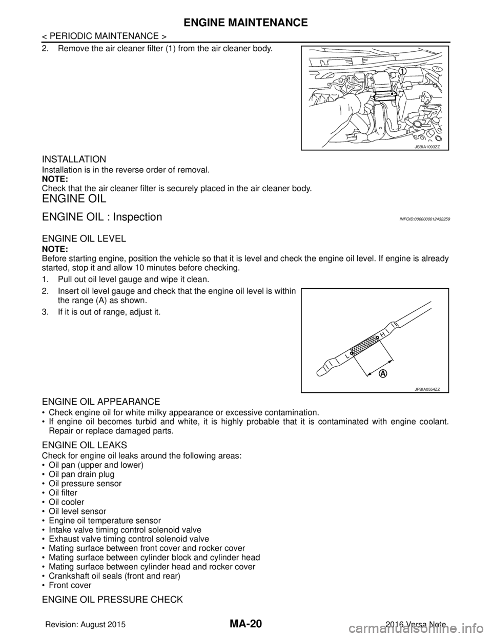
2. Remove the air cleaner filter (1) from the air cleaner body.
INSTALLATION
Installation is in the reverse order of removal.
NOTE:
Check that the air cleaner filter is securely placed in the air cleaner body.
ENGINE OIL
ENGINE OIL : InspectionINFOID:0000000012432259
ENGINE OIL LEVEL
NOTE:
Before starting engine, position the vehicle so that it is level and check the engine oil level. If engine is already
started, stop it and allow 10 minutes before checking.
1. Pull out oil level gauge and wipe it clean.
2. Insert oil level gauge and check that the engine oil level is withinthe range (A) as shown.
3. If it is out of range, adjust it.
ENGINE OIL APPEARANCE
• Check engine oil for white milky appearance or excessive contamination.
• If engine oil becomes turbid and white, it is highl y probable that it is contaminated with engine coolant.
Repair or replace damaged parts.
ENGINE OIL LEAKS
Check for engine oil leaks around the following areas:
• Oil pan (upper and lower)
• Oil pan drain plug
• Oil pressure sensor
• Oil filter
• Oil cooler
• Oil level sensor
• Engine oil temperature sensor
• Intake valve timing control solenoid valve
• Exhaust valve timing control solenoid valve
• Mating surface between front cover and rocker cover
• Mating surface between cylinder block and cylinder head
• Mating surface between cylinder head and rocker cover
• Crankshaft oil seals (front and rear)
• Front cover
ENGINE OIL PRESSURE CHECK
JSBIA1093ZZ
JPBIA0554ZZ
Revision: August 2015 2016 Versa Note
cardiagn.com
Page 2336 of 3641
ENGINE MAINTENANCEMA-21
< PERIODIC MAINTENANCE >
C
DE
F
G H
I
J
K L
M B
MA
N
O A
WARNING:
• Be careful not to burn yoursel
f, as engine oil may be hot.
• When checking engine oil pressure, sh ift selector should be in the "P" (Park) or "N" (Neutral) posi-
tion, and apply parking brake securely.
1. Check engine oil level.
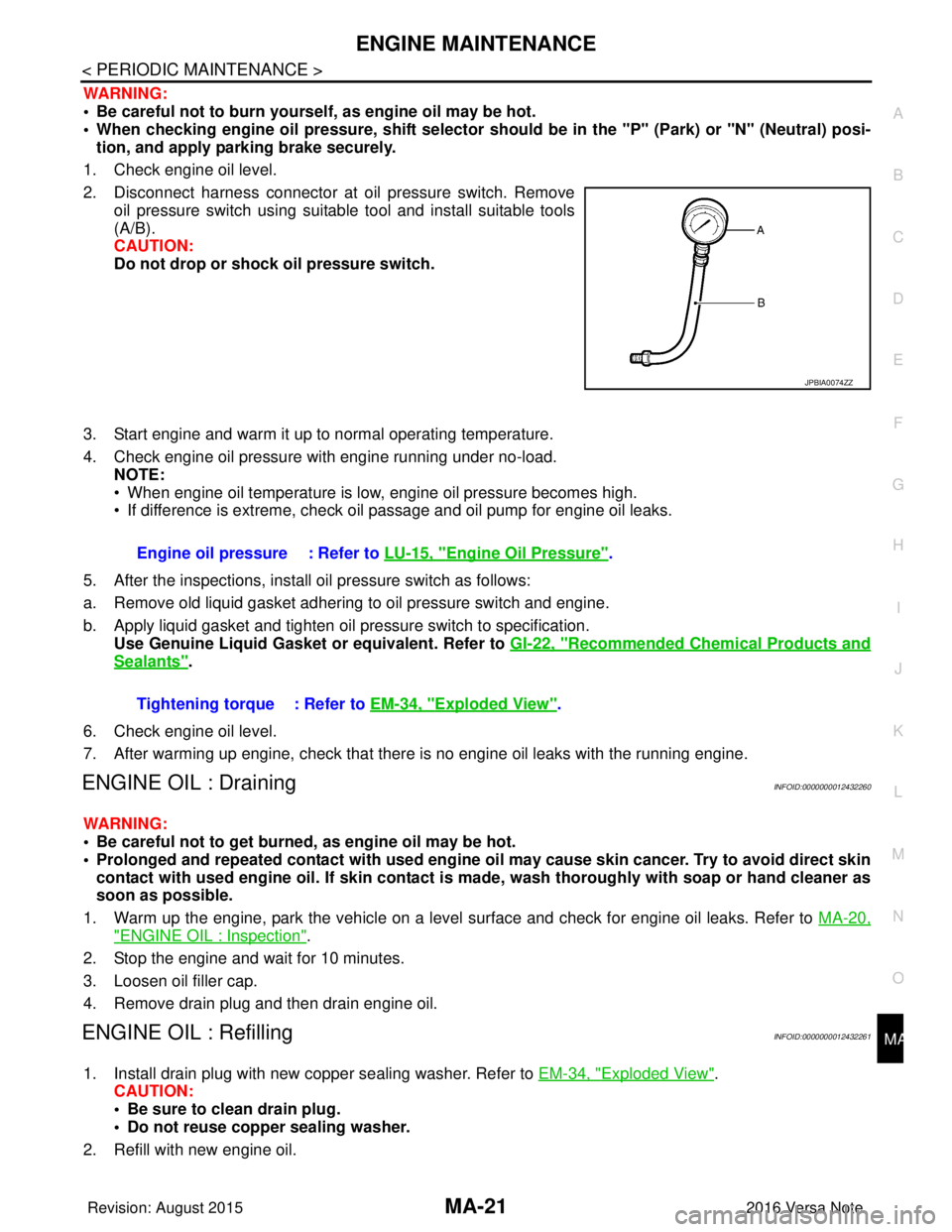
2. Disconnect harness connector at oil pressure switch. Remove oil pressure switch using suitable tool and install suitable tools
(A/B).
CAUTION:
Do not drop or shock oil pressure switch.
3. Start engine and warm it up to normal operating temperature.
4. Check engine oil pressure with engine running under no-load. NOTE:
• When engine oil temperature is low, engine oil pressure becomes high.
• If difference is extreme, check oil passage and oil pump for engine oil leaks.
5. After the inspections, install oil pressure switch as follows:
a. Remove old liquid gasket adhering to oil pressure switch and engine.
b. Apply liquid gasket and tighten oil pressure switch to specification. Use Genuine Liquid Gasket or equivalent. Refer to GI-22, "
Recommended Chemical Products and
Sealants".
6. Check engine oil level.
7. After warming up engine, check that there is no engine oil leaks with the running engine.
ENGINE OIL : DrainingINFOID:0000000012432260
WARNING:
• Be careful not to get burned, as engine oil may be hot.
• Prolonged and repeated contact with used engine oil may cause skin cancer. Try to avoid direct skin
contact with used engine oil. If skin contact is made, wash thorough ly with soap or hand cleaner as
soon as possible.
1. Warm up the engine, park the vehicle on a level surface and check for engine oil leaks. Refer to MA-20,
"ENGINE OIL : Inspection".
2. Stop the engine and wait for 10 minutes.
3. Loosen oil filler cap.
4. Remove drain plug and then drain engine oil.
ENGINE OIL : RefillingINFOID:0000000012432261
1. Install drain plug with new copper sealing washer. Refer to EM-34, "Exploded View".
CAUTION:
• Be sure to clean drain plug.
• Do not reuse copper sealing washer.
2. Refill with new engine oil.
JPBIA0074ZZ
Engine oil pressure : Refer to LU-15, "Engine Oil Pressure".
Tightening torque : Refer to EM-34, "
Exploded View".
Revision: August 2015 2016 Versa Note
cardiagn.com
Page 2342 of 3641
CHASSIS AND BODY MAINTENANCEMA-27
< PERIODIC MAINTENANCE >
C
DE
F
G H
I
J
K L
M B
MA
N
O A
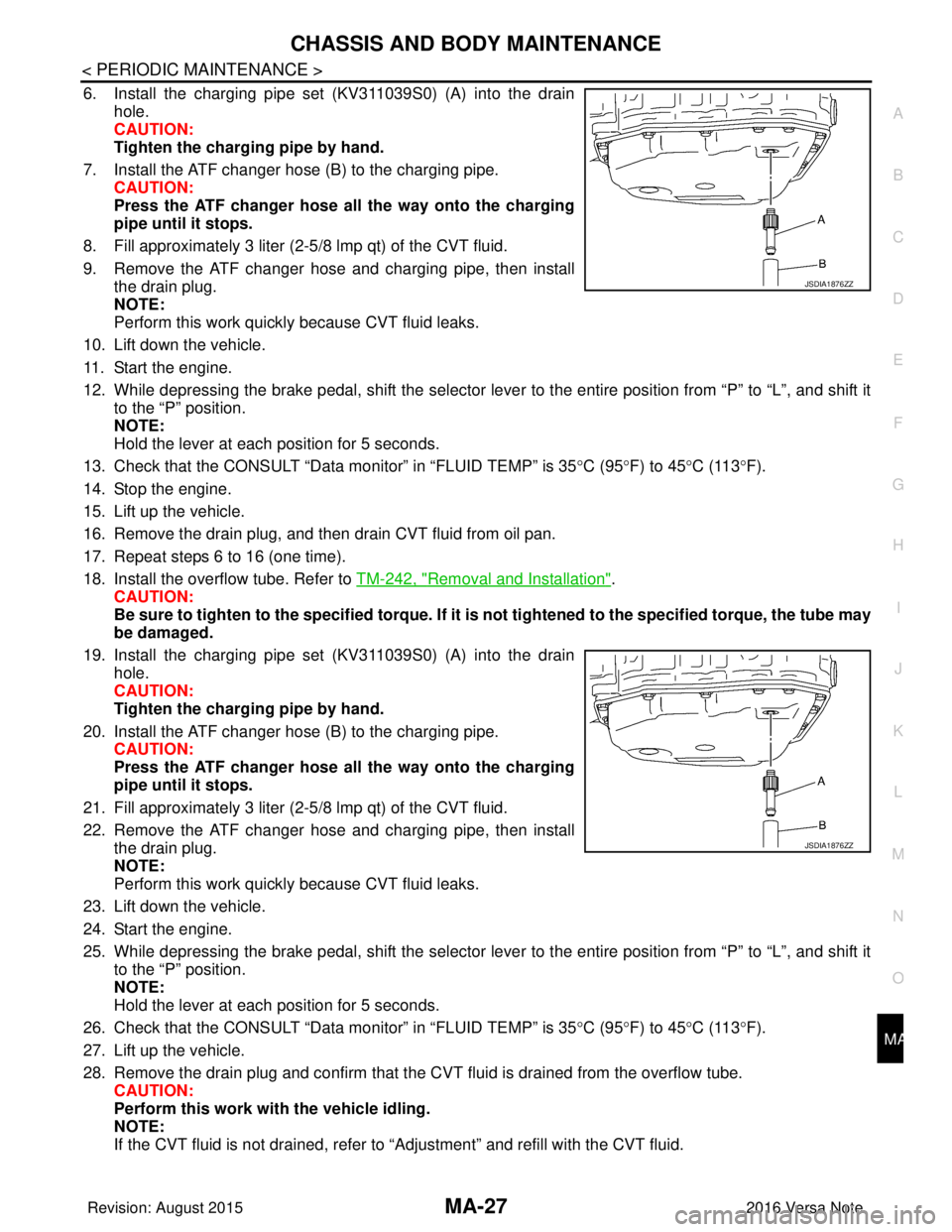
6. Install the charging pipe set (KV311039S0) (A) into the drain
hole.
CAUTION:
Tighten the charging pipe by hand.
7. Install the ATF changer hose (B) to the charging pipe. CAUTION:
Press the ATF changer hose all the way onto the charging
pipe until it stops.
8. Fill approximately 3 liter (2-5 /8 lmp qt) of the CVT fluid.
9. Remove the ATF changer hose and charging pipe, then install the drain plug.
NOTE:
Perform this work quickly because CVT fluid leaks.
10. Lift down the vehicle.
11. Start the engine.
12. While depressing the brake pedal, shift the selector leve r to the entire position from “P” to “L”, and shift it
to the “P” position.
NOTE:
Hold the lever at each position for 5 seconds.
13. Check that the CONSULT “Data monitor” in “FLUID TEMP” is 35°C (95°F) to 45 °C (113 °F).
14. Stop the engine.
15. Lift up the vehicle.
16. Remove the drain plug, and then drain CVT fluid from oil pan.
17. Repeat steps 6 to 16 (one time).
18. Install the overflow tube. Refer to TM-242, "
Removal and Installation".
CAUTION:
Be sure to tighten to the specified torque. If it is not tightened to the specified torque, the tube may
be damaged.
19. Install the charging pipe set (KV311039S0) (A) into the drain hole.
CAUTION:
Tighten the charging pipe by hand.
20. Install the ATF changer hose (B) to the charging pipe. CAUTION:
Press the ATF changer hose all the way onto the charging
pipe until it stops.
21. Fill approximately 3 liter (2-5 /8 lmp qt) of the CVT fluid.
22. Remove the ATF changer hose and charging pipe, then install the drain plug.
NOTE:
Perform this work quickly because CVT fluid leaks.
23. Lift down the vehicle.
24. Start the engine.
25. While depressing the brake pedal, shift the selector leve r to the entire position from “P” to “L”, and shift it
to the “P” position.
NOTE:
Hold the lever at each position for 5 seconds.
26. Check that the CONSULT “Data monitor” in “FLUID TEMP” is 35°C (95°F) to 45 °C (113 °F).
27. Lift up the vehicle.
28. Remove the drain plug and confirm that the CV T fluid is drained from the overflow tube.
CAUTION:
Perform this work with the vehicle idling.
NOTE:
If the CVT fluid is not drained, refer to “Adjustment” and refill with the CVT fluid.
JSDIA1876ZZ
JSDIA1876ZZ
Revision: August 2015 2016 Versa Note
cardiagn.com
Page 2343 of 3641
MA-28
< PERIODIC MAINTENANCE >
CHASSIS AND BODY MAINTENANCE
29. When the flow of CVT fluid slows to a drip, tighten the drain plug to the specified torque. TM-242,
"Removal and Installation".
CAUTION:
Never reuse drain plug gasket.
30. Lift down the vehicle.
31. Select “Work Support” in “TRANSMISSION” using CONSULT.
32. Select “CONFORM CVTF DETERIORTN”.
33. Select “Erase”.
34. Stop the engine.
CVT FLUID : AdjustmentINFOID:0000000012432269
CAUTION:
• Use only Genuine NISSAN CVT Fluid NS-3. Using transmission fluid other than Genuine NISSAN
CVT Fluid NS-3 will damage the CVT, which is not covered by the (NISSAN new vehicle limited) war-
ranty.
• During adjustment of the CVT fluid level, check CO NSULT so that the oil temperature may be main-
tained from 35 to 45 °C (95 to 113 °F).
• Use caution when looking into the drain hole as th ere is a risk of dripping fluid entering the eye.
1. Check that the selector lever is in the “P ” position, then completely engage the parking brake.
2. Start the engine.
3. Adjust the CVT fluid temperature to be approximately 40 °C (104° F).
NOTE:
The CVT fluid is largely affected by temperature. Therefore be sure to use CONSULT and check the
“FLUID TEMP” under “TRANSMISSION” in “Data Monitor” while adjusting.
4. While depressing the brake pedal, shift the selector lever to the entire position from “P” to “L”, and shift it to the “P” position.
NOTE:
Hold the lever at each position for 5 seconds.
5. Lift up the vehicle.
6. Check that there is no CVT fluid leakage.
7. Remove the drain plug. Refer to TM-242, "
Removal and Installation".
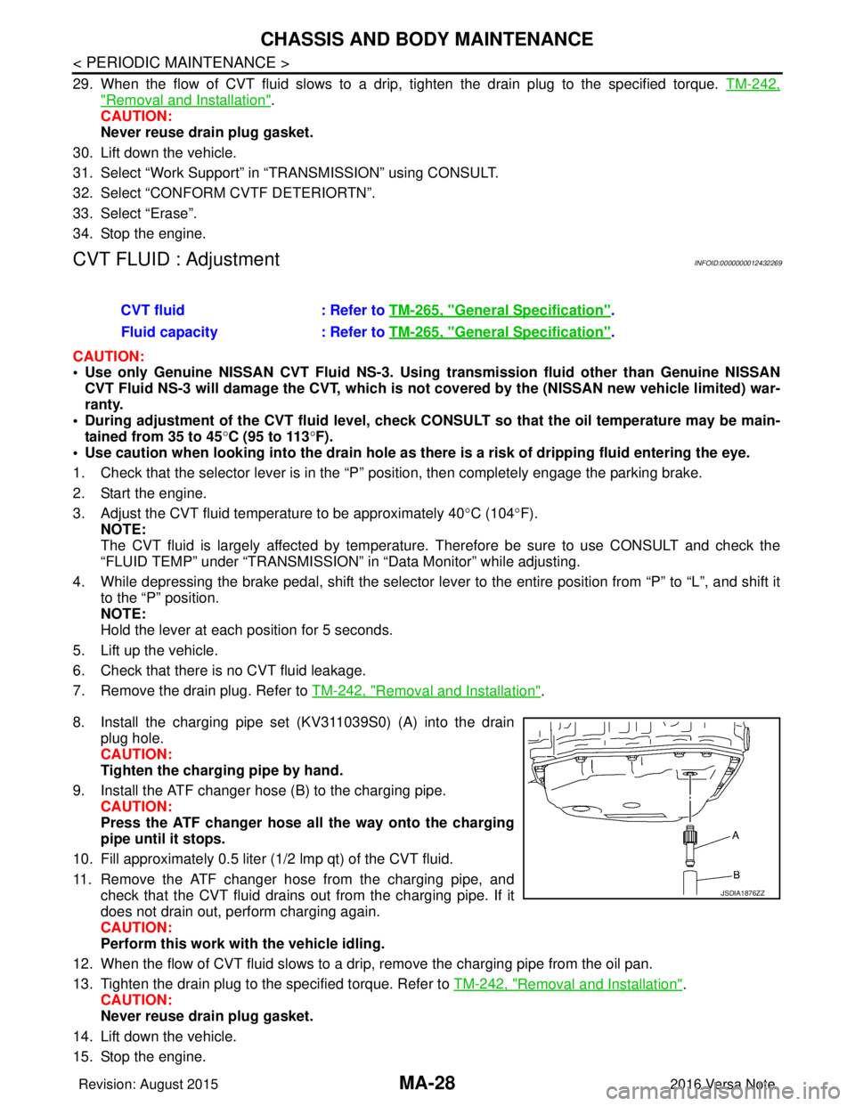
8. Install the charging pipe set (KV311039S0) (A) into the drain plug hole.
CAUTION:
Tighten the charging pipe by hand.
9. Install the ATF changer hose (B) to the charging pipe. CAUTION:
Press the ATF changer hose all the way onto the charging
pipe until it stops.
10. Fill approximately 0.5 liter (1/2 lmp qt) of the CVT fluid.
11. Remove the ATF changer hose from the charging pipe, and check that the CVT fluid drains out from the charging pipe. If it
does not drain out, perform charging again.
CAUTION:
Perform this work with the vehicle idling.
12. When the flow of CVT fluid slows to a drip, remove the charging pipe from the oil pan.
13. Tighten the drain plug to the specified torque. Refer to TM-242, "
Removal and Installation".
CAUTION:
Never reuse drain plug gasket.
14. Lift down the vehicle.
15. Stop the engine. CVT fluid
: Refer to TM-265, "
General Specification".
Fluid capacity : Refer to TM-265, "
General Specification".
JSDIA1876ZZ
Revision: August 2015 2016 Versa Note
cardiagn.com
Page 2346 of 3641
CHASSIS AND BODY MAINTENANCEMA-31
< PERIODIC MAINTENANCE >
C
DE
F
G H
I
J
K L
M B
MA
N
O A
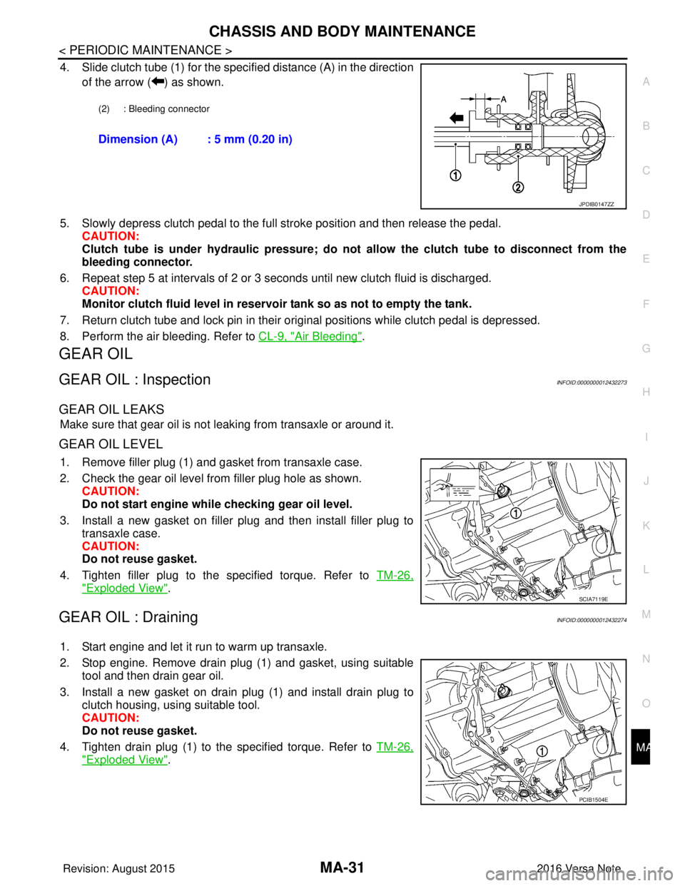
4. Slide clutch tube (1) for the specified distance (A) in the direction
of the arrow ( ) as shown.
5. Slowly depress clutch pedal to the full stroke position and then release the pedal. CAUTION:
Clutch tube is under hydraulic pressure; do not allow the clutch tube to disconnect from the
bleeding connector.
6. Repeat step 5 at intervals of 2 or 3 seconds until new clutch fluid is discharged. CAUTION:
Monitor clutch fluid level in reservoir tank so as not to empty the tank.
7. Return clutch tube and lock pin in their original positions while clutch pedal is depressed.
8. Perform the air bleeding. Refer to CL-9, "
Air Bleeding".
GEAR OIL
GEAR OIL : InspectionINFOID:0000000012432273
GEAR OIL LEAKS
Make sure that gear oil is not leaking from transaxle or around it.
GEAR OIL LEVEL
1. Remove filler plug (1) and gasket from transaxle case.
2. Check the gear oil level from filler plug hole as shown.
CAUTION:
Do not start engine whil e checking gear oil level.
3. Install a new gasket on filler plug and then install filler plug to transaxle case.
CAUTION:
Do not reuse gasket.
4. Tighten filler plug to the specified torque. Refer to TM-26,
"Exploded View".
GEAR OIL : DrainingINFOID:0000000012432274
1. Start engine and let it run to warm up transaxle.
2. Stop engine. Remove drain plug (1) and gasket, using suitable
tool and then drain gear oil.
3. Install a new gasket on drain plug (1) and install drain plug to clutch housing, using suitable tool.
CAUTION:
Do not reuse gasket.
4. Tighten drain plug (1) to the specified torque. Refer to TM-26,
"Exploded View".
(2) : Bleeding connector
Dimension (A) : 5 mm (0.20 in)
JPDIB0147ZZ
SCIA7119E
PCIB1504E
Revision: August 2015 2016 Versa Note
cardiagn.com