2016 NISSAN NOTE tow
[x] Cancel search: towPage 1791 of 3641
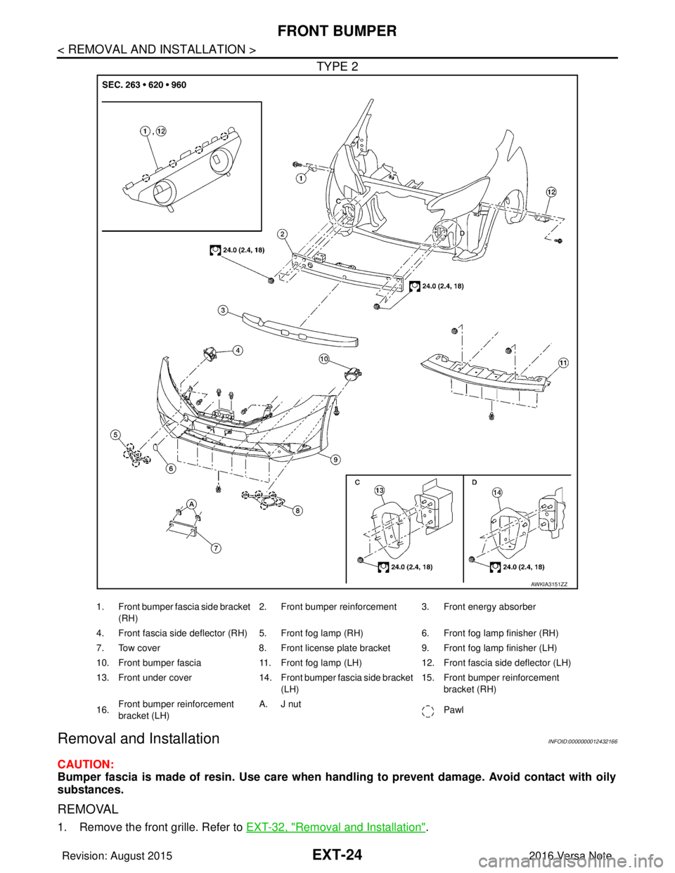
EXT-24
< REMOVAL AND INSTALLATION >
FRONT BUMPER
TYPE 2
Removal and InstallationINFOID:0000000012432166
CAUTION:
Bumper fascia is made of resin. Use care when handling to prevent damage. Avoid contact with oily
substances.
REMOVAL
1. Remove the front grille. Refer to EXT-32, "Removal and Installation".
AWKIA3151ZZ
1. Front bumper fascia side bracket
(RH) 2. Front bumper reinforcement 3. Front energy absorber
4. Front fascia side deflector (RH) 5. Front fog lamp (RH) 6. Front fog lamp finisher (RH)
7. Tow cover 8. Front license plate bracket 9. Front fog lamp finisher (LH)
10. Front bumper fascia 11. Front fog lamp (LH)12. Front fascia side deflector (LH)
13. Front under cover 14. Front bumper fascia side bracket
(LH) 15. Front bumper reinforcement
bracket (RH)
16. Front bumper reinforcement
bracket (LH) A. J nut
Pawl
Revision: August 2015 2016 Versa Note
cardiagn.com
Page 1792 of 3641
FRONT BUMPEREXT-25
< REMOVAL AND INSTALLATION >
C
DE
F
G H
I
J
L
M A
B
EXT
N
O P
2. Remove the four front bumper fascia upper clips.
3. Remove the front under cover. Refer to EXT-39, "
FRONT UNDER COVER : Removal and Installation".
4. Partially remove front fender protectors (LH/RH) at the front edge to access front bumper fascia bolts.
Refer to EXT-38, "
Exploded View".
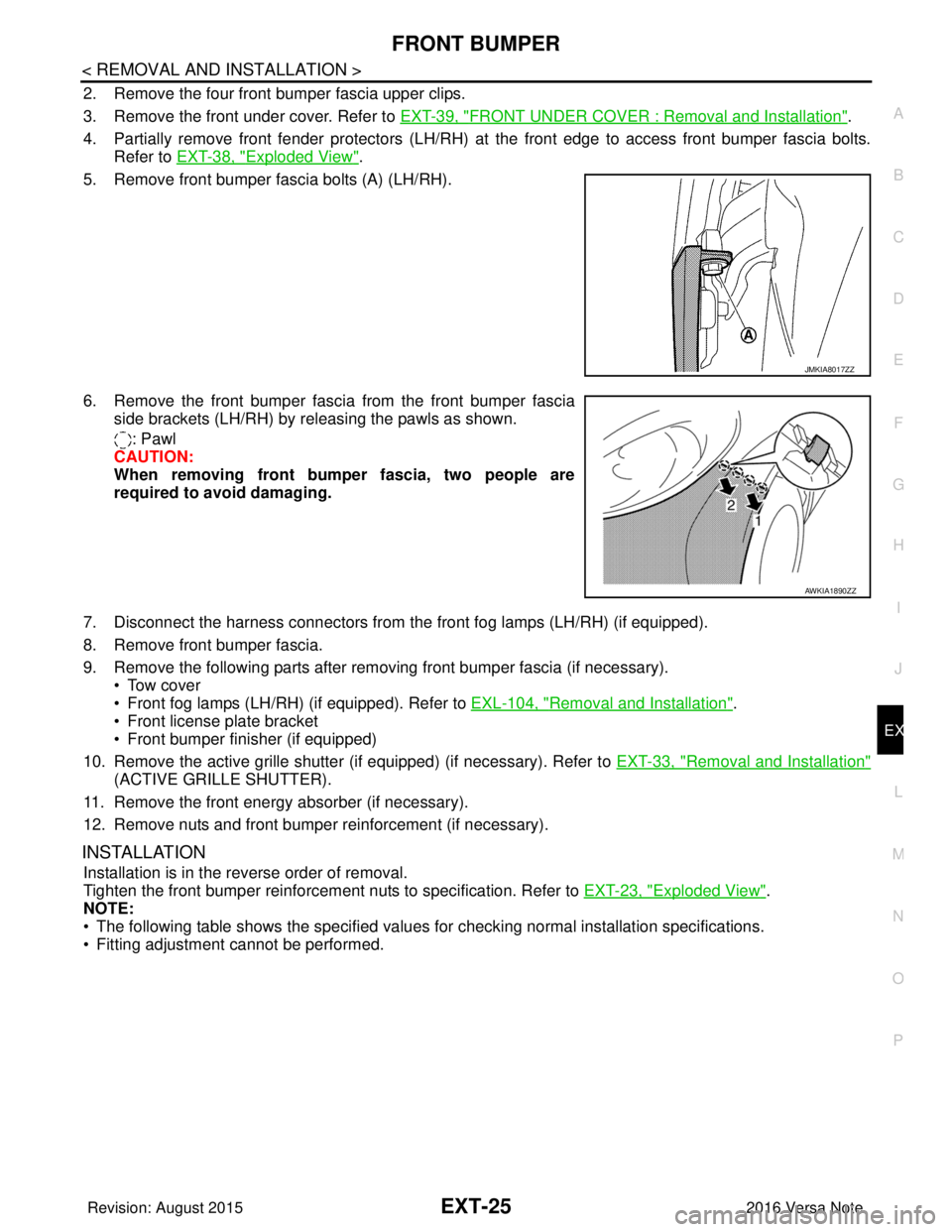
5. Remove front bumper fascia bolts (A) (LH/RH).
6. Remove the front bumper fasci a from the front bumper fascia
side brackets (LH/RH) by releasing the pawls as shown.
: Pawl
CAUTION:
When removing front bumper fascia, two people are
required to avoid damaging.
7. Disconnect the harness connectors from t he front fog lamps (LH/RH) (if equipped).
8. Remove front bumper fascia.
9. Remove the following parts after removing front bumper fascia (if necessary). • Tow cover
• Front fog lamps (LH/RH) (if equipped). Refer to EXL-104, "
Removal and Installation".
• Front license plate bracket
• Front bumper finisher (if equipped)
10. Remove the active grille shutter (if equipped) (if necessary). Refer to EXT-33, "
Removal and Installation"
(ACTIVE GRILLE SHUTTER).
11. Remove the front energy absorber (if necessary).
12. Remove nuts and front bumper reinforcement (if necessary).
INSTALLATION
Installation is in the reverse order of removal.
Tighten the front bumper reinforcement nuts to specification. Refer to EXT-23, "
Exploded View".
NOTE:
• The following table shows the specified values for checking normal installation specifications.
• Fitting adjustment cannot be performed.
JMKIA8017ZZ
AWKIA1890ZZ
Revision: August 2015 2016 Versa Note
cardiagn.com
Page 1810 of 3641
ROOF SIDE MOLDINGEXT-43
< REMOVAL AND INSTALLATION >
C
DE
F
G H
I
J
L
M A
B
EXT
N
O P
Removal
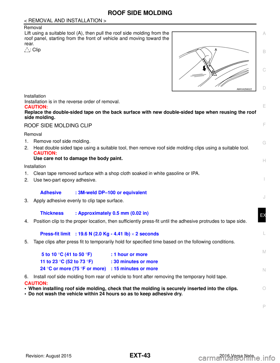
Lift using a suitable tool (A), then pull the roof side molding from the
roof panel, starting from the front of vehicle and moving toward the
rear.
: Clip
Installation
Installation is in the reverse order of removal.
CAUTION:
Replace the double-sided tape on the back surface with new double-sided tape when reusing the roof
side molding.
ROOF SIDE MOLDING CLIP
Removal
1. Remove roof side molding.
2. Heat double sided tape using a suitable tool, then remove roof side molding clips using a suitable tool.
CAUTION:
Use care not to damage the body paint.
Installation
1. Clean tape removed surface with a shop cloth soaked in white gasoline or IPA.
2. Use two-part epoxy adhesive.
3. Apply adhesive evenly to clip tape surface.
4. Position clip to the proper location, then sufficient ly press-fit until the adhesive protrudes to tape side.
5. Tape clips after press fit to temporarily hold for specified time based on the following conditions.
6. Install roof side molding from rear of vehicle to front after removing the temporary hold tape.
CAUTION:
• When installing roof side moldin g, check that the molding is securely inserted into the clips.
• Do not wash the vehicle within 24 hours so as to keep adhesive dry.
AWKIA2560ZZ
Adhesive : 3M-weld DP–100 or equivalent
Thickness : Approximately 0.5 mm (0.02 in)
Press-fit limit : 19.6 N (2.0 Kg - 4.41 lb) × 2 seconds
5 to 10 °C (41 to 50 °F) : 1 hour or more
11 to 23 °C (52 to 73 °F) : 30 minutes or more
24 °C or more (75 °F or more) : 15 minutes or more
Revision: August 2015 2016 Versa Note
cardiagn.com
Page 1814 of 3641

DOOR OUTSIDE MOLDINGEXT-47
< REMOVAL AND INSTALLATION >
C
DE
F
G H
I
J
L
M A
B
EXT
N
O P
Removal and InstallationINFOID:0000000012432189
FRONT DOOR OUTSIDE MOLDING
Removal
1. Lower front door glass fully.
2. Release the pawls using a suitable tool, then rotate front door outside molding toward the outside of the vehicle and lift up to remove.
Installation
Installation is in the reverse order of removal.
REAR DOOR OUTSIDE MOLDING
Removal
1. Lower rear door glass fully.
2. Release the pawl using a suitable tool, then rotate rear door outside molding toward the outside of the
vehicle and lift up to remove.
Installation
Installation is in the reverse order of removal.
4. Rear door panel 5. Rear door glass6. Front door glass
Pawl
Revision: August 2015 2016 Versa Note
cardiagn.com
Page 1889 of 3641

GI-1
GENERAL INFORMATION
C
DE
F
G H
I
J
K L
M B
GI
SECTION GI
N
O P
CONTENTS
GENERAL INFORMATION
HOW TO USE THIS MANU AL ......................3
HOW TO USE THIS MANUAL ....................... .....3
Description .......................................................... ......3
Terms ........................................................................3
Units ..........................................................................3
Contents ....................................................................3
Relation between Illustrations and Descriptions .......4
Components ..............................................................4
HOW TO FOLLOW TROUBLE DIAGNOSES .....6
Description ................................................................6
How to Follow Test Groups in Trouble Diagnosis ......6
Key to Symbols Signifying Measurements or Pro-
cedures ............................................................... ......
7
HOW TO READ WIRING DIAGRAMS ................9
Connector Symbols ............................................. ......9
Sample/Wiring Diagram -Example- .........................10
Connector Information .............................................12
ABBREVIATIONS .......................................... ....14
Abbreviation List .................................................. ....14
TIGHTENING TORQUE OF STANDARD
BOLTS ................................................................
19
Description .......................................................... ....19
Tightening Torque Table (New Standard Includ-
ed) ...........................................................................
19
RECOMMENDED CHEMICAL PRODUCTS
AND SEALANTS ................................................
22
Recommended Chemical Products and Sealants ....22
PRECAUTION ..............................................23
PRECAUTIONS .............................................. ....23
Description .......................................................... ....23
Precaution for Supplemental Restraint System
(SRS) "AIR BAG" and "SEAT BELT PRE-TEN-
SIONER" .................................................................
23
Procedures without Cowl Top Cover .......................23
Cautions in Removing Battery Terminal and AV
Control Unit (Models with AV Control Unit) .............
23
General Precautions ............................................ ....24
Three Way Catalyst .................................................25
Fuel ..........................................................................25
Multiport Fuel Injection System or Engine Control
System .....................................................................
26
Hoses ......................................................................26
Engine Oils ..............................................................27
Air Conditioning .......................................................27
LIFTING POINT .................................................28
Special Service Tool ................................................28
Garage Jack and Safety Stand ................................28
2-Pole Lift ................................................................29
Board-on Lift ............................................................30
TOW TRUCK TOWING .....................................31
Tow Truck Towing ...................................................31
Vehicle Recovery (Freeing a Stuck Vehicle) ...........31
VEHICLE INFORMATION ...........................33
IDENTIFICATION INFORMATION ....................33
Model Variation .................................................... ....33
Identification Number ...............................................34
Identification Plate ...................................................35
Engine Serial Number .............................................36
CVT Number ............................................................36
Manual Transaxle Number ......................................36
Dimensions ..............................................................36
Wheels & Tires ........................................................37
BASIC INSPECTION ...................................38
SERVICE INFORMATION FOR ELECTRICAL
INCIDENT ..........................................................
38
Work Flow ............................................................ ....38
Control Units and Electrical Parts ............................38
How to Check Terminal ...........................................39
Intermittent Incident ............................................. ....42
Circuit Inspection .....................................................44
Revision: August 2015 2016 Versa Note
cardiagn.com
Page 1919 of 3641
TOW TRUCK TOWINGGI-31
< PRECAUTION >
C
DE
F
G H
I
J
K L
M B
GI
N
O PTOW TRUCK TOWING
To w T r u c k To w i n gINFOID:0000000012433173
CAUTION:
• Never tow a CVT model with the rear wheels raised and the front wheels on the ground. This may
cause serious and expensive damage to the transaxle. If it is necessary to tow the vehicle with the
rear wheels raised, always use towin g dollies under the front wheels.
• Never tow a CVT model from the rear (that is b ackward) with four wheels on the ground. This may
cause serious and expensive damage to the transaxle.
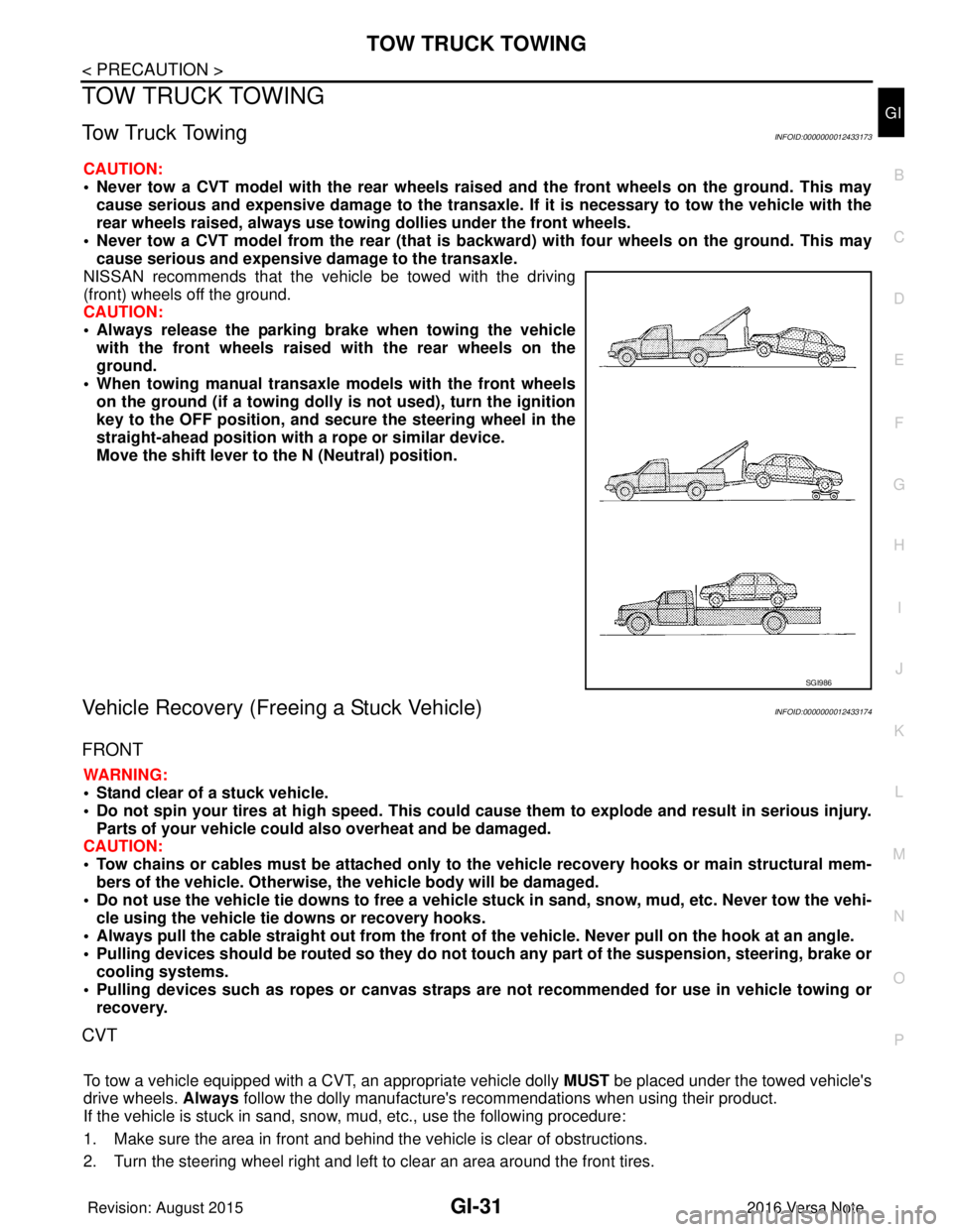
NISSAN recommends that the vehicle be towed with the driving
(front) wheels off the ground.
CAUTION:
• Always release the parking br ake when towing the vehicle
with the front wheels raised with the rear wheels on the
ground.
• When towing manual transaxle models with the front wheels on the ground (if a towing dolly is not used), turn the ignition
key to the OFF position, and secu re the steering wheel in the
straight-ahead position with a rope or similar device.
Move the shift lever to th e N (Neutral) position.
Vehicle Recovery (Freeing a Stuck Vehicle)INFOID:0000000012433174
FRONT
WARNING:
• Stand clear of a stuck vehicle.
• Do not spin your tires at high speed. This could cause them to explode and result in serious injury.
Parts of your vehicle could also overheat and be damaged.
CAUTION:
• Tow chains or cables must be attached only to the vehicle recovery hooks or main structural mem-
bers of the vehicle. Otherwise, the vehicle body will be damaged.
• Do not use the vehicle tie downs to free a vehicle stuck in sand, snow, mud, etc. Never tow the vehi-
cle using the vehicle tie downs or recovery hooks.
• Always pull the cable straight out from the front of the vehicle. Never pull on the hook at an angle.
• Pulling devices should be routed so they do not touch any part of the suspension, steering, brake or
cooling systems.
• Pulling devices such as ropes or canvas straps ar e not recommended for use in vehicle towing or
recovery.
CVT
To tow a vehicle equipped with a CVT, an appropriate vehicle dolly MUST be placed under the towed vehicle's
drive wheels. Always follow the dolly manufacture's re commendations when using their product.
If the vehicle is stuck in sand, snow , mud, etc., use the following procedure:
1. Make sure the area in front and behind the vehicle is clear of obstructions.
2. Turn the steering wheel right and left to clear an area around the front tires.
SGI986
Revision: August 2015 2016 Versa Note
cardiagn.com
Page 1920 of 3641

GI-32
< PRECAUTION >
TOW TRUCK TOWING
3. Slowly rock the vehicle forward and backward.Shift back and forth between R (reverse) and D (drive).
Apply the accelerator as little as possible to maintain the rocking motion.
Release the accelerator pedal before shifting between R and D.
Do not spin the tires above 35 m.p.h. (55 km/h).
4. If the vehicle can not be freed after a few tries, contact a professional towing service to remove the vehi- cle.
Revision: August 2015 2016 Versa Note
cardiagn.com
Page 1962 of 3641
GW-22
< REMOVAL AND INSTALLATION >
FRONT DOOR GLASS AND REGULATOR
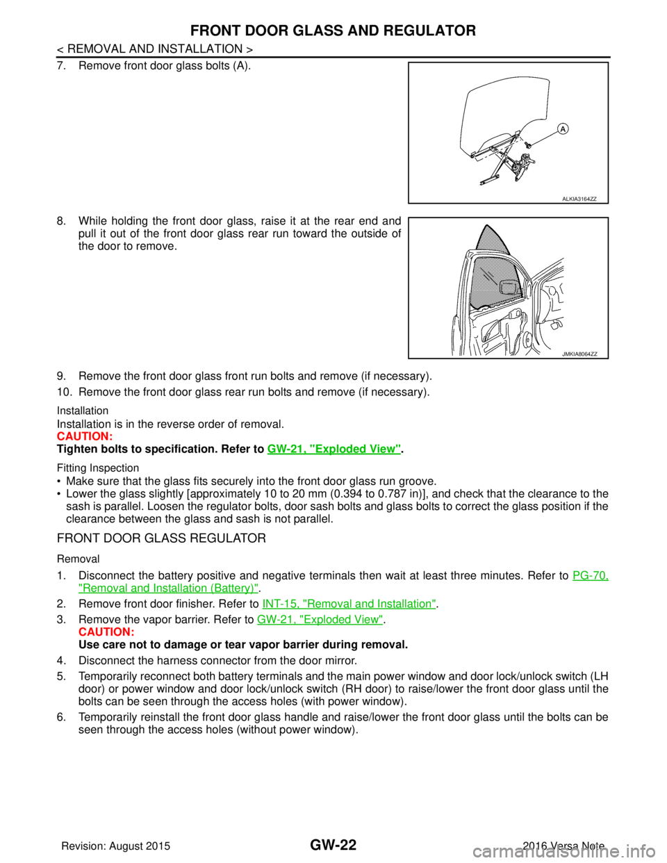
7. Remove front door glass bolts (A).
8. While holding the front door glass, raise it at the rear end andpull it out of the front door glass rear run toward the outside of
the door to remove.
9. Remove the front door glass front run bolts and remove (if necessary).
10. Remove the front door glass rear run bolts and remove (if necessary).
Installation
Installation is in the reverse order of removal.
CAUTION:
Tighten bolts to specification. Refer to GW-21, "
Exploded View".
Fitting Inspection
• Make sure that the glass fits securely into the front door glass run groove.
• Lower the glass slightly [approximately 10 to 20 mm (0.394 to 0.787 in)], and check that the clearance to the
sash is parallel. Loosen the regulator bolts, door sash bolts and glass bolts to correct the glass position if the
clearance between the glass and sash is not parallel.
FRONT DOOR GLASS REGULATOR
Removal
1. Disconnect the battery positive and negative terminal s then wait at least three minutes. Refer to PG-70,
"Removal and Installation (Battery)".
2. Remove front door finisher. Refer to INT-15, "
Removal and Installation".
3. Remove the vapor barrier. Refer to GW-21, "
Exploded View".
CAUTION:
Use care not to damage or tear vapor barrier during removal.
4. Disconnect the harness connector from the door mirror.
5. Temporarily reconnect both battery terminals and the main power window and door lock/unlock switch (LH door) or power window and door lock/unlock switch (RH door) to raise/lower the front door glass until the
bolts can be seen through the access holes (with power window).
6. Temporarily reinstall the front door glass handle and raise/lower the front door glass until the bolts can be seen through the access holes (without power window).
ALKIA3164ZZ
JMKIA8064ZZ
Revision: August 2015 2016 Versa Note
cardiagn.com