2016 NISSAN NOTE tow
[x] Cancel search: towPage 991 of 3641
![NISSAN NOTE 2016 Service Repair Manual DLK-302
< REMOVAL AND INSTALLATION >[WITHOUT INTELLIGENT KEY SYSTEM]
REAR DOOR LOCK
5. Remove front gasket and rear gasket.
6. Slide outside handle bracket toward rear of vehicle to remove.
: Front
7. NISSAN NOTE 2016 Service Repair Manual DLK-302
< REMOVAL AND INSTALLATION >[WITHOUT INTELLIGENT KEY SYSTEM]
REAR DOOR LOCK
5. Remove front gasket and rear gasket.
6. Slide outside handle bracket toward rear of vehicle to remove.
: Front
7.](/manual-img/5/57363/w960_57363-990.png)
DLK-302
< REMOVAL AND INSTALLATION >[WITHOUT INTELLIGENT KEY SYSTEM]
REAR DOOR LOCK
5. Remove front gasket and rear gasket.
6. Slide outside handle bracket toward rear of vehicle to remove.
: Front
7. Disconnect outside handle cable (1) from outside handle bracket (2) as shown.
INSTALLATION
Installation is in the reverse order of removal.
CAUTION:
• After installation, check door op en/close, lock/unlock operation.
• Check door lock cable is properly engaged with outside handle bracket.
JMKIA5890ZZ
JMKIA5891ZZ
Revision: August 2015 2016 Versa Note
cardiagn.com
Page 1055 of 3641
![NISSAN NOTE 2016 Service Repair Manual EM-54
< REMOVAL AND INSTALLATION >[HR16DE]
TIMING CHAIN
b. Cut liquid gasket by prying the position ( ) as shown, and then
remove the front cover.
12. Remove front oil seal from front cover using a su NISSAN NOTE 2016 Service Repair Manual EM-54
< REMOVAL AND INSTALLATION >[HR16DE]
TIMING CHAIN
b. Cut liquid gasket by prying the position ( ) as shown, and then
remove the front cover.
12. Remove front oil seal from front cover using a su](/manual-img/5/57363/w960_57363-1054.png)
EM-54
< REMOVAL AND INSTALLATION >[HR16DE]
TIMING CHAIN
b. Cut liquid gasket by prying the position ( ) as shown, and then
remove the front cover.
12. Remove front oil seal from front cover using a suitable tool. CAUTION:
Be careful not to damage the front cover.
13. Remove chain tensioner (1):
a. Fully push down the chain tensioner lever (A), and then push the plunger (C) into the inside of tensioner.
• The tab (B) is released by fully pushing the lever down. Thenthe plunger can be moved.
b. Pull up the lever to align its hole position with the body hole posi- tion.
• When the lever hole is aligned with the body hole position, theplunger is secured.
• When the protrusion parts of the plunger ratchet and the tab face each other, both hole positions are not aligned. At that
time, correctly engage them and align these hole positions by
slightly moving the plunger.
c. Insert the stopper pin (D) into the body hole through the lever hole, and then secure the lever at the upper position.
NOTE:
A hexagonal wrench of 2.5 mm (0.098 in) is used as a stopper pin (D).
d. Remove chain tensioner.
14. Remove the timing chain tension guide (2) and the timing chain slack guide (1).
15. Remove the timing chain (2). • Pull the timing chain slack toward the camshaft sprocket
(EXH) (1), and then remove the timing chain and start the
removal from camshaft sprocket (EXH) side.
CAUTION:
Do not rotate crankshaft or camshaft while timing chain is
removed. It causes interferen ce between valve and piston.
16. Remove the crankshaft sprocket and the oil pump drive:
JPBIA4140ZZ
PBIC3713E
JPBIA4141ZZ
JPBIA4142ZZ
Revision: August 2015 2016 Versa Note
cardiagn.com
Page 1057 of 3641
![NISSAN NOTE 2016 Service Repair Manual EM-56
< REMOVAL AND INSTALLATION >[HR16DE]
TIMING CHAIN
a. Install the crankshaft sprocket (1), the oil pump drive chain (2),
and the oil pump sprocket (3) at the same time.
• Install the crankshaft NISSAN NOTE 2016 Service Repair Manual EM-56
< REMOVAL AND INSTALLATION >[HR16DE]
TIMING CHAIN
a. Install the crankshaft sprocket (1), the oil pump drive chain (2),
and the oil pump sprocket (3) at the same time.
• Install the crankshaft](/manual-img/5/57363/w960_57363-1056.png)
EM-56
< REMOVAL AND INSTALLATION >[HR16DE]
TIMING CHAIN
a. Install the crankshaft sprocket (1), the oil pump drive chain (2),
and the oil pump sprocket (3) at the same time.
• Install the crankshaft sprocket so that its invalid gear area (A)is toward the back of the engine.
• Install the oil pump sprocket so that its protrusion faces the front of engine.
NOTE:
There is no matching mark in the oil pump drive related parts.
b. Hold the top of the oil pump shaft using the socket (size: E8), and then tighten the oil pump sprocket nut.
c. Install oil pump drive chain tensioner (1). • Insert the body into the shaft (B) while inserting the spring intothe attaching hole (A) of cylinder block front surface.
• Check that the tension is applied to the oil pump drive chain
after installing.
2. Install timing chain:
• Install by aligning matching marks on each sprocket and tim-ing chain.
• If these matching marks are not aligned, rotate the camshaft
slightly to correct the position.
CAUTION:
• After the matching marks are aligned, keep them aligned by holding them.
• To avoid skipped teeth, do not rotate crankshaft and cam- shaft until front cover is installed.
: Engine front
JPBIA5248ZZ
(1) : Crankshaft sprocket
(2) : Oil pump drive chain
(3) : Oil pump sprocket
JPBIA4230ZZ
JPBIA4143ZZ
(A) : Matching mark (Peripheral groove)
(B) : Pink link
(C) : Matching mark (Peripheral groove)
(D) : Orange link
(E) : Matching mark (stamp)
(F) : Crankshaft key (point straight up)
JPBIA4144ZZ
Revision: August 2015 2016 Versa Note
cardiagn.com
Page 1098 of 3641
![NISSAN NOTE 2016 Service Repair Manual CYLINDER BLOCKEM-97
< UNIT DISASSEMBLY AND ASSEMBLY > [HR16DE]
C
D
E
F
G H
I
J
K L
M A
EM
NP
O
3. Install oil jets.
4. Install main bearings and thrust bearings:
a. Remove dust, dirt, and engine oil o NISSAN NOTE 2016 Service Repair Manual CYLINDER BLOCKEM-97
< UNIT DISASSEMBLY AND ASSEMBLY > [HR16DE]
C
D
E
F
G H
I
J
K L
M A
EM
NP
O
3. Install oil jets.
4. Install main bearings and thrust bearings:
a. Remove dust, dirt, and engine oil o](/manual-img/5/57363/w960_57363-1097.png)
CYLINDER BLOCKEM-97
< UNIT DISASSEMBLY AND ASSEMBLY > [HR16DE]
C
D
E
F
G H
I
J
K L
M A
EM
NP
O
3. Install oil jets.
4. Install main bearings and thrust bearings:
a. Remove dust, dirt, and engine oil on the bear
ing mating surfaces of cylinder block.
b. Install thrust bearings to the both sides of the No. 3 journal hous- ing (B) on cylinder block.
• Install thrust bearings with the oil groove (A) facing crankshaftarm (outside).
c. Install the main bearings paying attention to the direction. • Before installing main bearings, apply new engine oil to the bearing surface (inside). Do not apply
engine oil to the back surface, but thoroughly clean it.
• When installing, align main bearing to the center position of cylinder block and main bearing cap.
• Ensure the oil holes on cylinder block and oil holes (A) on the
main bearings (1) are aligned.
NOTE:
For assembly, the center position can be visually identified.
• To install the main bearing, obtain a proper fit. Do not allow the main bearing to lie off the cylinder block chamfer.
• To install the main bearing, obtain a proper fit. Do not allow the
main bearing to lie off bearing cap chamfer.
5. Install signal plate to crankshaft if removed.
a. Set the signal plate (1) with the flange facing toward the counter- weight side (engine front side) to the crankshaft rear surface.
b. After positioning crankshaft and signal plate with positioning dowel pin, tighten bolt.
NOTE:
Dowel pin of crankshaft and signal plate is provided as a set for
each.
c. Remove dowel pin. CAUTION:
Be sure to remove dowel pin.
6. Install crankshaft to cylinder block. • While turning crankshaft by hand, check that it turns smoothly.
CAUTION:
Do not install rear oil seal at this time.
7. Install main bearing caps.
: Engine front
PBIC3258J
PBIC3746E
(A) : Dowel pin hole
JPBIA4231ZZ
Revision: August 2015 2016 Versa Note
cardiagn.com
Page 1102 of 3641
![NISSAN NOTE 2016 Service Repair Manual CYLINDER BLOCKEM-101
< UNIT DISASSEMBLY AND ASSEMBLY > [HR16DE]
C
D
E
F
G H
I
J
K L
M A
EM
NP
O
Install the rear oil seal after installing the oil pan (upper).
17. Install rear oil seal. Refer to EM- NISSAN NOTE 2016 Service Repair Manual CYLINDER BLOCKEM-101
< UNIT DISASSEMBLY AND ASSEMBLY > [HR16DE]
C
D
E
F
G H
I
J
K L
M A
EM
NP
O
Install the rear oil seal after installing the oil pan (upper).
17. Install rear oil seal. Refer to EM-](/manual-img/5/57363/w960_57363-1101.png)
CYLINDER BLOCKEM-101
< UNIT DISASSEMBLY AND ASSEMBLY > [HR16DE]
C
D
E
F
G H
I
J
K L
M A
EM
NP
O
Install the rear oil seal after installing the oil pan (upper).
17. Install rear oil seal. Refer to EM-74, "
REAR OIL SEAL : Removal and Installation".
18. Install flywheel (M/T models) or drive plate (CVT models).
M/T models
• Secure crankshaft with a stopper plate and tighten bolts crosswise over several times.
CVT models
• Secure crankshaft with a stopper plate and tighten bolts crosswise over several times.
CAUTION:
Do not damage or scratch and contact surface for clutch disc of flywheel.
19. Install knock sensor (1).
• Install connectors so that they are positioned toward the rearof the engine.
CAUTION:
• Do not tighten bolt while holding the connector.
• If any impact by dropping is applied to knock sensor,
replace it with a new one.
NOTE:
• Check that there is no foreign material on the cylinder block
mating surface and the back surface of knock sensor.
• Check that knock sensor does not interfere with other parts.
20. Install crankshaft position sensor (POS) (2) and O-ring (1) and then install the crankshaft position sensor cover (3) on the cylin-
der block (4).
• Tighten bolts with sensor inserted completely.
CAUTION:
• Avoid impacts such as a dropping.
• Do not disassemble.
• Keep sensor away from metal particles.
• Do not place the sensor in a location where it is exposedto magnetism.
• Do not reuse O-ring.
21. For the oil level gauge guide (1), secure in position (B) shown to the water inlet clip (A) after inserting to the cylinder block side.
22. Assembly of the remaining components is in the reverse order of disassembly.
Tool number : KV11105210 (J-44716)
Tool number : KV11105210 (J-44716)
: Engine front
: Engine front
PBIC3754E
JPBIA4202ZZ
PBIC3755E
Revision: August 2015
2016 Versa Note
cardiagn.com
Page 1749 of 3641

HEADLAMP AIMING ADJUSTMENTEXL-97
< PERIODIC MAINTENANCE >
C
DE
F
G H
I
J
K
M A
B
EXL
N
O P
PERIODIC MAINTENANCE
HEADLAMP AIMING ADJUSTMENT
InspectionINFOID:0000000012432828
PREPARATION BEFORE ADJUSTING
Before performing aiming adjustment, check the following:
• Ensure all tires are inflated to correct pressure.
• Place vehicle and screen on level surface.
• Ensure there is no load in vehicle other than the driver (or equivalent weight placed in driver's position).
• Coolant and engine oil filled to correct level, and fuel tank full.
• Remove cargo and/or luggage to maintain an unloaded vehicle condition.
• Confirm spare tire, jack and tools are properly stowed.
• Carefully wipe off any dirt from headlamp lens. CAUTION:
Do not use organic solvent (thinner, gasoline etc.)
• Place a driver or equivalent weight of 68.5 kg (150 lb) on the driver seat.
• By hand, bounce the front and rear of the vehicle to settle the suspension and eliminate any static load.
• Place the front tires in the straight ahead position.
• Confirm headlamp aiming switch is set to "0" (zero) position.
• Aim each headlamp individually and ensure other headlamp beam pattern is blocked from screen.
NOTE:
• For headlamp aiming details, refer to regulations in your area.
• By regulation, no means for horizontal aim adjustment is provided from the factory; only vertical aim is
adjustable.
• Use adjusting screw to perform aiming adjustment.
• Perform headlamp aiming if:
- The vehicle front body has been repaired.
- The front combination lamp has been removed or replaced.
- Any outfitting has been installed.
- The vehicle’s standard load condition has been substantially increased.
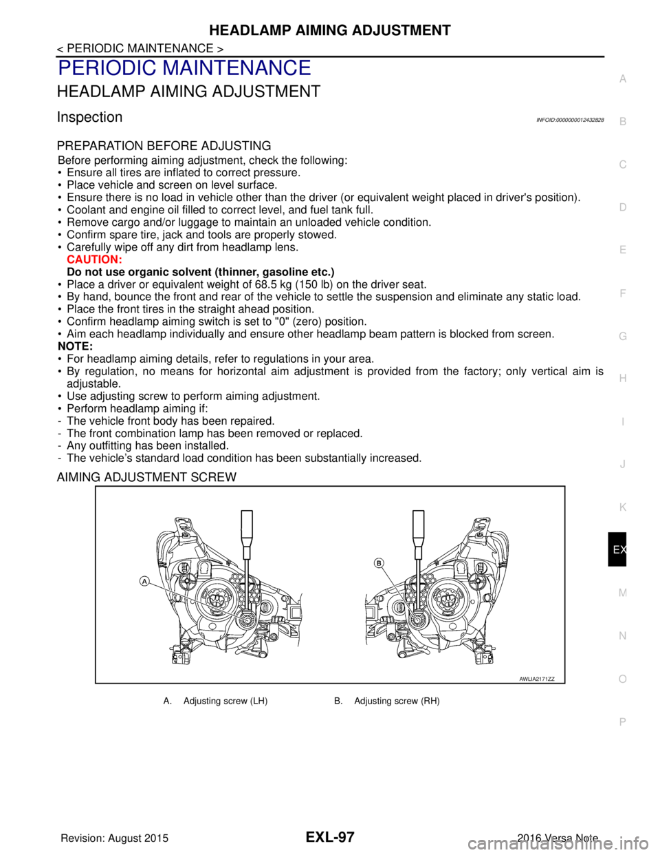
AIMING ADJUSTMENT SCREW
AWLIA2171ZZ
A. Adjusting screw (LH) B. Adjusting screw (RH)
Revision: August 2015 2016 Versa Note
cardiagn.com
Page 1752 of 3641

EXL-100
< PERIODIC MAINTENANCE >
FRONT FOG LAMP AIMING ADJUSTMENT
FRONT FOG LAMP AIMING ADJUSTMENT
InspectionINFOID:0000000012432830
PREPARATION BEFORE ADJUSTING
Before performing aiming adjustment procedure, check the following:
• Ensure all tires are inflated to correct pressure.
• Place vehicle and screen on level surface.
• Ensure there is no load in vehicle other than the driver (or equivalent weight placed in driver's position).
• Coolant and engine oil filled to correct level, and fuel tank full.
• Remove cargo and/or luggage to maintain an unloaded vehicle condition.
• Confirm spare tire, jack and tools are properly stowed.
• Carefully wipe off any dirt from fog lamp lens. CAUTION:
Do not use organic solvent (thinner, gasoline etc.)
• Place a driver or equivalent weight of 68.5 kg (150 lb) on the driver seat.
• By hand, bounce the front and rear of the vehicle to settle the suspension and eliminate any static load.
• Place the front tires in the straight ahead position.
• Aim each headlamp individually and ensure other headlamp beam pattern is blocked from screen.
NOTE:
• For headlamp aiming details, refer to regulations in your area.
• By regulation, no means for horizontal aim adjustment is provided from the factory; only vertical aim is
adjustable.
• Use adjusting screw to perform aiming adjustment.
• Perform headlamp aiming if:
- The vehicle front body has been repaired.
- The front combination lamp has been removed or replaced.
- Any outfitting has been installed.
- The vehicle’s standard load condition has been substantially increased.
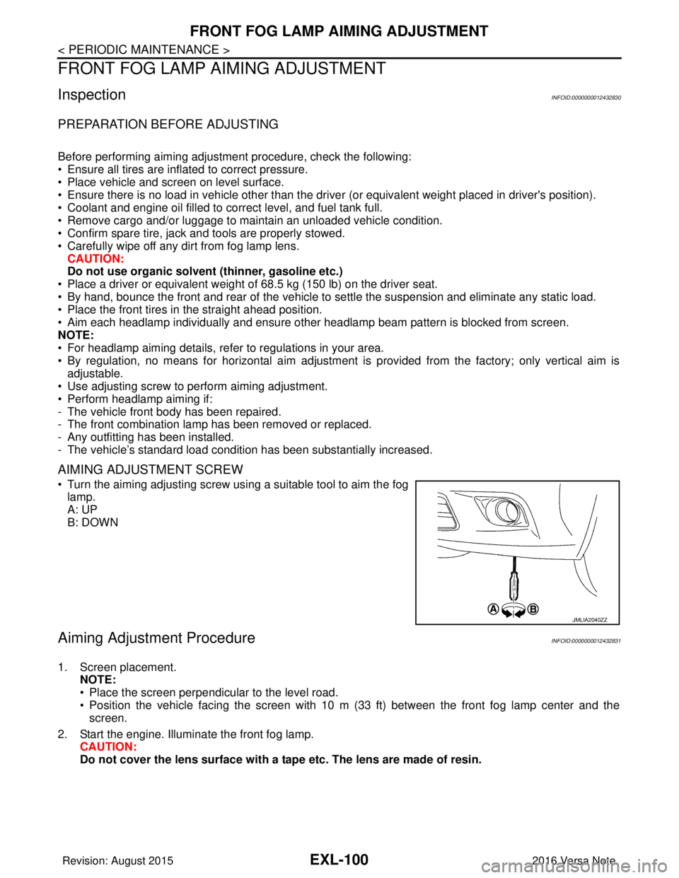
AIMING ADJUSTMENT SCREW
• Turn the aiming adjusting screw using a suitable tool to aim the fog
lamp.
A: UP
B: DOWN
Aiming Adjustment ProcedureINFOID:0000000012432831
1. Screen placement. NOTE:
• Place the screen perpendicular to the level road.
• Position the vehicle facing the screen with 10 m (33 ft) between the front fog lamp center and thescreen.
2. Start the engine. Illuminate the front fog lamp. CAUTION:
Do not cover the lens surface with a tape etc. The lens are made of resin.
JMLIA2040ZZ
Revision: August 2015 2016 Versa Note
cardiagn.com
Page 1790 of 3641

FRONT BUMPEREXT-23
< REMOVAL AND INSTALLATION >
C
DE
F
G H
I
J
L
M A
B
EXT
N
O P
REMOVAL AND INSTALLATION
FRONT BUMPER
Exploded ViewINFOID:0000000012432165
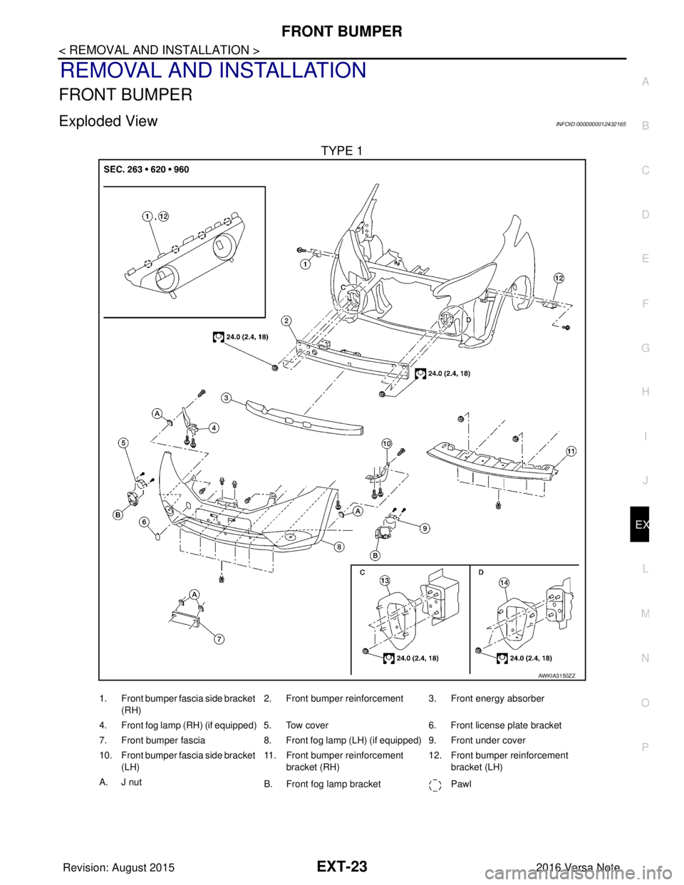
TYPE 1
AWKIA3150ZZ
1. Front bumper fascia side bracket (RH) 2. Front bumper reinforcement 3. Front energy absorber
4. Front fog lamp (RH) (if equipped) 5. Tow cover 6. Front license plate bracket
7. Front bumper fascia 8. Front fog lamp (LH) (if equipped) 9. Front under cover
10. Front bumper fascia side bracket (LH) 11. Front bumper reinforcement
bracket (RH) 12. Front bumper reinforcement
bracket (LH)
A. J nut B. Front fog lamp bracket Pawl
Revision: August 2015 2016 Versa Note
cardiagn.com