2016 NISSAN NOTE stop start
[x] Cancel search: stop startPage 2876 of 3641
![NISSAN NOTE 2016 Service Repair Manual DIAGNOSIS SYSTEM (BCM)SEC-19
< SYSTEM DESCRIPTION > [WITH INTELLIGENT KEY SYSTEM]
C
D
E
F
G H
I
J
L
M A
B
SEC
N
O P
INTELLIGENT KEY
INTELLIGENT KEY : CONSULT Func tion (BCM - INTELLIGENT KEY)INFOID:00 NISSAN NOTE 2016 Service Repair Manual DIAGNOSIS SYSTEM (BCM)SEC-19
< SYSTEM DESCRIPTION > [WITH INTELLIGENT KEY SYSTEM]
C
D
E
F
G H
I
J
L
M A
B
SEC
N
O P
INTELLIGENT KEY
INTELLIGENT KEY : CONSULT Func tion (BCM - INTELLIGENT KEY)INFOID:00](/manual-img/5/57363/w960_57363-2875.png)
DIAGNOSIS SYSTEM (BCM)SEC-19
< SYSTEM DESCRIPTION > [WITH INTELLIGENT KEY SYSTEM]
C
D
E
F
G H
I
J
L
M A
B
SEC
N
O P
INTELLIGENT KEY
INTELLIGENT KEY : CONSULT Func tion (BCM - INTELLIGENT KEY)INFOID:0000000012542526
SELF DIAGNOSTIC RESULT
Refer to BCS-50, "DTCIndex".
DATA MONITOR
ACTIVE TEST
Monitor Item [Unit] Main Description
REQ SW -DR [On/Off] ×Indicates condition of door request switch LH.
REQ SW -AS [On/Off] ×Indicates condition of door request switch RH.
REQ SW -BD/TR [On/Off] ×Indicates condition of back door request switch.
PUSH SW [On/Off] Indicates condition of push-button ignition switch.
CLUCH SW [On/Off] ×Indicates condition of clutch interlock switch.
BRAKE SW 1 [On/Off] ×Indicates condition of brake switch.
BRAKE SW 2 [On/Off] Indicates condition of brake switch.
DETE/CANCL SW [On/Off] ×Indicates condition of P (park) position.
SFT PN/N SW [On/Off] ×Indicates condition of P (park) or N (neutral) position.
UNLK SEN -DR [On/Off] ×Indicates condition of door unlock sensor.
PUSH SW -IPDM [On/Off] Indicates condition of push-button ignition switch received from IPDM E/R on
CAN communication line.
IGN RLY1 -F/B [On/Off] Indicates condition of ignition relay 1 received from IPDM E/R on CAN commu-
nication line.
DETE SW -IPDM [On/Off] Indicates condition of detent switch received from TCM on CAN communication
line.
SFT PN -IPDM [On/Off] Indicates condition of P (park) or N (neutral) position from TCM on CAN com-
munication line.
SFT P -MET [On/Off] Indicates condition of P (park) position from TCM on CAN communication line.
SFT N -MET [On/Off] Indicates condition of N (neutral) position from IPDM E/R on CAN communica-
tion line.
ENGINE STATE [Stop/Start/Crank/Run] ×Indicates condition of engine state from ECM on CAN communication line.
VEH SPEED 1 [mph/km/h] ×Indicates condition of vehicle speed si
gnal received from ABS on CAN commu-
nication line.
VEH SPEED 2 [mph/km/h] ×Indicates condition of vehicle speed signal received from combination meter on
CAN communication line.
DOOR STAT -DR [LOCK/READY/UNLK] ×Indicates condition of driver side door status.
DOOR STAT -AS [LOCK/READY/UNLK] ×Indicates condition of passenger side door status.
ID OK FLAG [Set/Reset] Indicates condition of Intelligent Key ID.
PRMT ENG STRT [Set/Reset] Indicates condition of engine start possibility.
RKE OPE COUN1 [0-19] ×When remote keyless entry receiver receives the signal transmitted while oper-
ating on Intelligent Key, the numerical value start changing.
RKE OPE COUN2 [0-19] ×When remote keyless entry receiver receives the signal transmitted while oper-
ating on Intelligent Key, the numerical value start changing.
RKE-LOCK [On/Off] Indicates condition of lock signal from Intelligent Key.
RKE-UNLOCK [On/Off] Indicates condition of unlock signal from Intelligent Key.
RKE-PANIC [On/Off] Indicates condition of panic signal from Intelligent Key.
RKE-MODE CHG [On/Off] Indicates condition of mode change signal from Intelligent Key.
Revision: August 2015 2016 Versa Note
cardiagn.com
Page 2977 of 3641
![NISSAN NOTE 2016 Service Repair Manual SEC-120
< SYSTEM DESCRIPTION >[WITHOUT INTELLIGENT KEY SYSTEM]
COMPONENT PARTS
No.
Component Function
1. Combination meter Combination meter transmits the vehicle
speed signal to BCM via CAN communic NISSAN NOTE 2016 Service Repair Manual SEC-120
< SYSTEM DESCRIPTION >[WITHOUT INTELLIGENT KEY SYSTEM]
COMPONENT PARTS
No.
Component Function
1. Combination meter Combination meter transmits the vehicle
speed signal to BCM via CAN communic](/manual-img/5/57363/w960_57363-2976.png)
SEC-120
< SYSTEM DESCRIPTION >[WITHOUT INTELLIGENT KEY SYSTEM]
COMPONENT PARTS
No.
Component Function
1. Combination meter Combination meter transmits the vehicle
speed signal to BCM via CAN communica-
tion.
BCM also receives the vehicle speed signal
from ABS actuator and electric unit (control
unit) via CAN communication. BCM com-
pares both signals to detect the vehicle
speed.
Security indicator lamp is located on combi-
nation meter.
Security indicator lamp blinks when ignition
switch is in any position other than ON to
warn that NISSAN VEHICLE IMMOBILIZER
SYSTEM-NATS [NVIS (NATS)] is on board.
Refer to MWI-8, "
METER SYSTEM : Compo-
nent Parts Location".
2. ABS actuator and electric unit (control unit) ABS actuator and electric unit (control unit)
transmits the vehicle speed signal to BCM via
CAN communication.
BCM also receives the vehicle speed signal
from the combination meter via CAN commu-
nication. BCM compares both signals to de-
tect the vehicle speed.
Refer to
BRC-7, "
Component Parts Location"
for detailed installation location.
3. Transmission range switch Transmission range switch detects the CVT
shift selector lever position.
4. IPDM E/R Starter control relay is used for the engine
starting function. Starter control relay is con-
trolled by IPDM E/R while communicating
with BCM. IPDM E/R se
nds the starter control
relay statu signal to BCM.
5. BCM BCM controls NISSAN VEHICLE IMMOBI-
LIZER SYSTEM-NATS [NVIS (NATS)] and
VEHICLE SECURITY SYSTEM.
When the ignition switch is turned ON, BCM
performs ID verification between BCM and
ECM. If the ID verification result is OK, ECM
can start engine.
Refer to
BCS-77, "
BODY CONTROL SYS-
TEM : Component Parts Location" for de-
tailed installation location.
6. Clutch interlock switch Clutch interlock switch detects that clutch
pedal is depressed, and then transmits ON/
OFF signal to the BCM.
7. Stop lamp switch Stop lamp switch detects that brake pedal is
depressed, and then transmits ON/OFF sig-
nal to the BCM.
8. Main power window and door lock/unlock switch Door lock and unlock switch is integrated into
the main power window and door lock/unlock
switch.
Door lock and unlock switch transmits door
lock/unlock operation signal to BCM.
Refer to
PWC-6, "
Component Parts Loca-
tion".
9. CVT shift selector (park position switch) Park position switch is integrated into the
CVT shift selector and detects that the selec-
tor lever is in the P (park) position, then trans-
mits ON/OFF signal to the BCM and IPDM E/
R.
Revision: August 2015
2016 Versa Note
cardiagn.com
Page 2979 of 3641
![NISSAN NOTE 2016 Service Repair Manual SEC-122
< SYSTEM DESCRIPTION >[WITHOUT INTELLIGENT KEY SYSTEM]
COMPONENT PARTS
NISSAN VEHICLE IMMOBILIZER SYSTEM-NATS : Door Switch
INFOID:0000000012430448
Door switch detects door open/close conditi NISSAN NOTE 2016 Service Repair Manual SEC-122
< SYSTEM DESCRIPTION >[WITHOUT INTELLIGENT KEY SYSTEM]
COMPONENT PARTS
NISSAN VEHICLE IMMOBILIZER SYSTEM-NATS : Door Switch
INFOID:0000000012430448
Door switch detects door open/close conditi](/manual-img/5/57363/w960_57363-2978.png)
SEC-122
< SYSTEM DESCRIPTION >[WITHOUT INTELLIGENT KEY SYSTEM]
COMPONENT PARTS
NISSAN VEHICLE IMMOBILIZER SYSTEM-NATS : Door Switch
INFOID:0000000012430448
Door switch detects door open/close conditi on and then transmits ON/OFF signal to BCM.
NISSAN VEHICLE IMMOBILIZER SYSTEM-NAT S : Remote Keyless Entry Receiver
INFOID:0000000012430449
Remote keyless entry receiver receives each button operation signal and electronic key ID signal from key
and then transmits the signal to BCM.
NISSAN VEHICLE IMMOBILIZER SYSTEM-NATS : Security Indicator Lamp
INFOID:0000000012430450
Security indicator lamp is located on combination meter.
Security indicator lamp blinks when power supply positi on is any position other than ON to warn that NISSAN
VEHICLE IMMOBILIZER SYSTEM-NATS (NATS) is on board.
NISSAN VEHICLE IMMOBILIZER SY STEM-NATS : Starter RelayINFOID:0000000012430451
Engine starting system functions by controlling starter control relay.
Starter control relay is controlled by IPDM E/R on request from BCM.
IPDM E/R transmits starter control relay statu signal to BCM via CAN communication.
NISSAN VEHICLE IMMOBILIZER SY STEM-NATS : Stop Lamp SwitchINFOID:0000000012430452
Stop lamp switch detects that brake pedal is depressed, and then transmits the signal to BCM.
NISSAN VEHICLE IMMOBILIZER SYSTEM-NATS : Transmission Range Switch
INFOID:0000000012430453
Transmission range switch is integrated in CVT assembly, and detects the CVT shift selector position.
TCM receives the transmission range switch signal and then transmits the P/N position signal to BCM and
IPDM E/R.
BCM confirms the CVT shift selector position with the following 5 signals:
• P (Park) position signal from CVT shift selector (park position switch)
• P/N position signal from TCM
• P (Park) position signal from IPDM E/R (CAN)
• P/N position signal from IPDM E/R (CAN)
• P/N position signal from TCM (CAN)
IPDM E/R confirms the CVT shift sele ctor position with the following 3 signals:
• P (Park) position signal from CVT shift selector (park position switch)
• P/N position signal from TCM
• P/N position signal from BCM (CAN)
Revision: August 2015 2016 Versa Note
cardiagn.com
Page 2986 of 3641
![NISSAN NOTE 2016 Service Repair Manual DIAGNOSIS SYSTEM (IPDM E/R)SEC-129
< SYSTEM DESCRIPTION > [WITHOUT INTELLIGENT KEY SYSTEM]
C
D
E
F
G H
I
J
L
M A
B
SEC
N
O P
ECU IDENTIFICATION
The IPDM E/R part number is displayed.
SELF DIAGNOSTIC R NISSAN NOTE 2016 Service Repair Manual DIAGNOSIS SYSTEM (IPDM E/R)SEC-129
< SYSTEM DESCRIPTION > [WITHOUT INTELLIGENT KEY SYSTEM]
C
D
E
F
G H
I
J
L
M A
B
SEC
N
O P
ECU IDENTIFICATION
The IPDM E/R part number is displayed.
SELF DIAGNOSTIC R](/manual-img/5/57363/w960_57363-2985.png)
DIAGNOSIS SYSTEM (IPDM E/R)SEC-129
< SYSTEM DESCRIPTION > [WITHOUT INTELLIGENT KEY SYSTEM]
C
D
E
F
G H
I
J
L
M A
B
SEC
N
O P
ECU IDENTIFICATION
The IPDM E/R part number is displayed.
SELF DIAGNOSTIC RESULT
Refer to PCS-20, "DTCIndex".
DATA MONITOR
ACTIVE TEST
Data Monitor The IPDM E/R input/output data is displayed in real time.
Active Test The IPDM E/R activates outputs to test components.
CAN Diag Support Mntr The result of transmit/receive diagnosis of CAN communication is displayed.
Direct Diagnostic Mode
Description
Monitor Item [Unit]Main
Signals Description
MOTOR FAN REQ [1/2/3/4] ×Indicates cooling fan speed signal received from ECM on CAN communication
line
AC COMP REQ [On/Off] ×Indicates A/C compressor request signal received from ECM on CAN commu-
nication line
TAIL&CLR REQ [On/Off] ×Indicates position light request signal
received from BCM on CAN communica-
tion line
HL LO REQ [On/Off] ×Indicates low beam request signal received from BCM on CAN communication
line
HL HI REQ [On/Off] ×Indicates high beam request signal received from BCM on CAN communication
line
FR FOG REQ [On/Off] ×Indicates front fog light request signal received from BCM on CAN communica-
tion line
FR WIP REQ [Stop/1LOW/Low/Hi] ×Indicates front wiper request signal received from BCM on CAN communication
line
WIP AUTO STOP [STOP P/ACT P] ×Indicates condition of front wiper auto stop signal
WIP PROT [Off/BLOCK] ×Indicates condition of front wiper fail-safe operation
IGN RLY1 -REQ [On/Off] Indicates ignition switch ON signal received from BCM on CAN communication
line
IGN RLY [On/Off] ×Indicates condition of ignition relay
PUSH SW [On/Off] Indicates condition of push-button ignition switch
INTER/NP SW [On/Off] Indicates condition of CVT shift position
ST RLY CONT [On/Off] Indicates starter relay status signal received from BCM on CAN communication
line
IHBT RLY -REQ [On/Off] Indicates starter control relay signal received from BCM on CAN communication
line
ST/INHI RLY [Off/ ST /INHI] Indicates condition of starter relay and starter control relay
DETENT SW [On/Off] Indicates condition of CVT shift selector (park position switch)
DTRL REQ [Off] Indicates daytime running light request signal received from BCM on CAN com-
munication line
THFT HRN REQ [On/Off] Indicates theft warning horn request signal received from BCM on CAN commu-
nication line
HORN CHIRP [On/Off] Indicates horn reminder signal received from BCM on CAN communication line
Test item Description
HORN This test is able to check horn operation [On].
FRONT WIPER This test is able to check wiper motor operation [Hi/Lo/Off].
Revision: August 2015 2016 Versa Note
cardiagn.com
Page 3178 of 3641

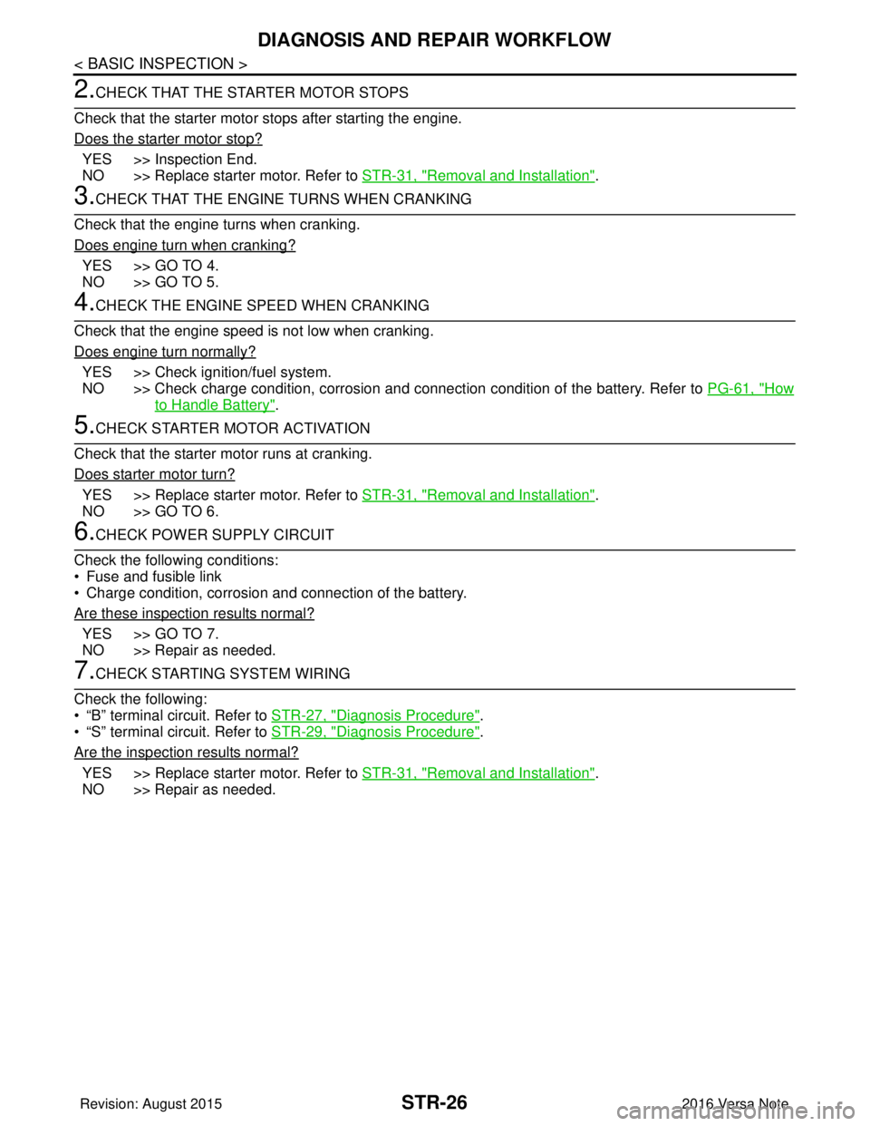
STR-26
< BASIC INSPECTION >
DIAGNOSIS AND REPAIR WORKFLOW
2.CHECK THAT THE STARTER MOTOR STOPS
Check that the starter motor stops after starting the engine.
Does the starter motor stop?
YES >> Inspection End.
NO >> Replace starter motor. Refer to STR-31, "
Removal and Installation".
3.CHECK THAT THE ENGINE TURNS WHEN CRANKING
Check that the engine turns when cranking.
Does engine turn when cranking?
YES >> GO TO 4.
NO >> GO TO 5.
4.CHECK THE ENGINE SPEED WHEN CRANKING
Check that the engine speed is not low when cranking.
Does engine turn normally?
YES >> Check ignition/fuel system.
NO >> Check charge condition, corrosion and connection condition of the battery. Refer to PG-61, "
How
to Handle Battery".
5.CHECK STARTER MOTOR ACTIVATION
Check that the starter motor runs at cranking.
Does starter motor turn?
YES >> Replace starter motor. Refer to STR-31, "Removal and Installation".
NO >> GO TO 6.
6.CHECK POWER SUPPLY CIRCUIT
Check the following conditions:
• Fuse and fusible link
• Charge condition, corrosion and connection of the battery.
Are these inspection results normal?
YES >> GO TO 7.
NO >> Repair as needed.
7.CHECK STARTING SYSTEM WIRING
Check the following:
• “B” terminal circuit. Refer to STR-27, "
Diagnosis Procedure".
• “S” terminal circuit. Refer to STR-29, "
Diagnosis Procedure".
Are the inspection results normal?
YES >> Replace starter motor. Refer to STR-31, "Removal and Installation".
NO >> Repair as needed.
Revision: August 2015 2016 Versa Note
cardiagn.com
Page 3216 of 3641

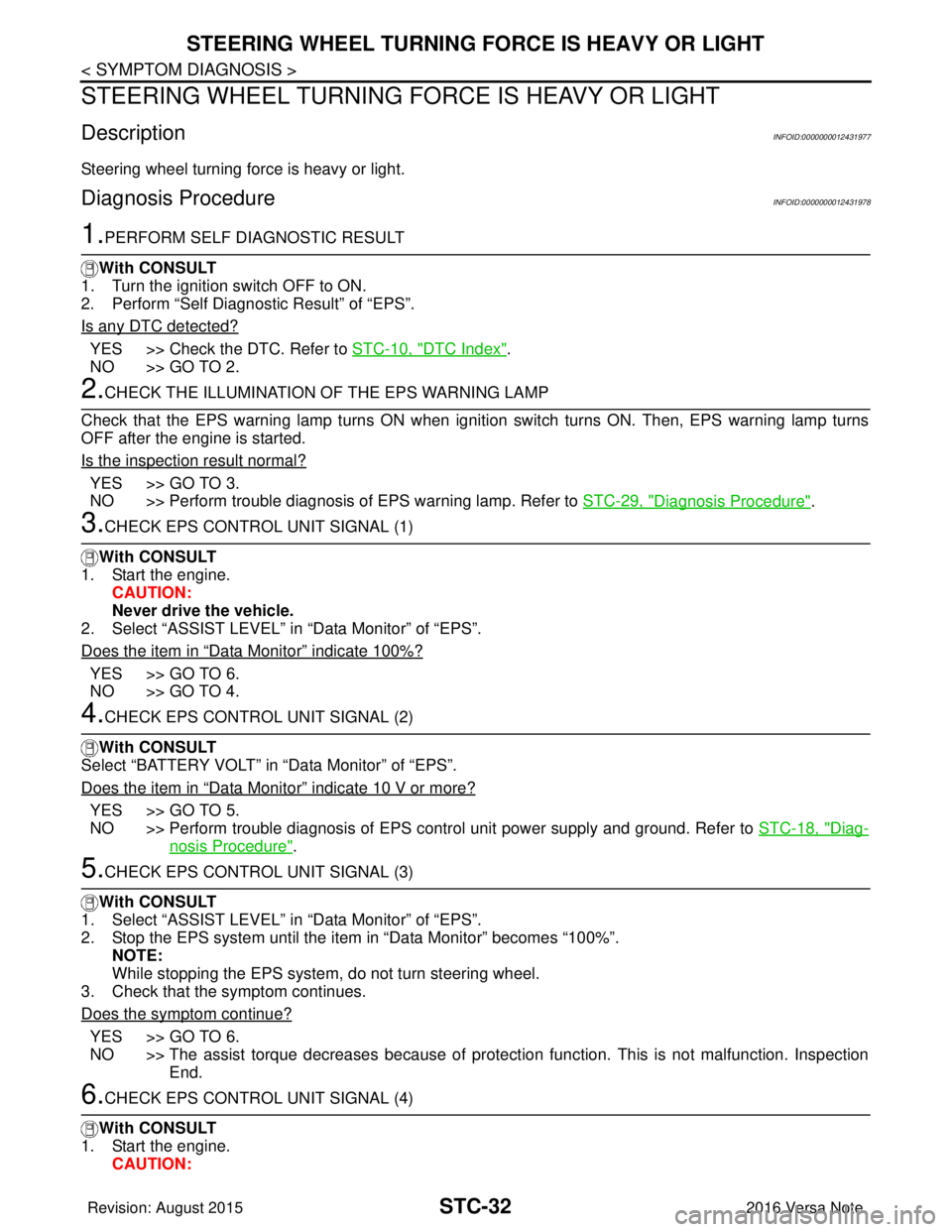
STC-32
< SYMPTOM DIAGNOSIS >
STEERING WHEEL TURNING FORCE IS HEAVY OR LIGHT
STEERING WHEEL TURNING FORCE IS HEAVY OR LIGHT
DescriptionINFOID:0000000012431977
Steering wheel turning force is heavy or light.
Diagnosis ProcedureINFOID:0000000012431978
1.PERFORM SELF DIAGNOSTIC RESULT
With CONSULT
1. Turn the ignition switch OFF to ON.
2. Perform “Self Diagnostic Result” of “EPS”.
Is any DTC detected?
YES >> Check the DTC. Refer to STC-10, "DTC Index".
NO >> GO TO 2.
2.CHECK THE ILLUMINATION OF THE EPS WARNING LAMP
Check that the EPS warning lamp turns ON when igni tion switch turns ON. Then, EPS warning lamp turns
OFF after the engine is started.
Is the inspection result normal?
YES >> GO TO 3.
NO >> Perform trouble diagnosis of EPS warning lamp. Refer to STC-29, "
Diagnosis Procedure".
3.CHECK EPS CONTROL UNIT SIGNAL (1)
With CONSULT
1. Start the engine. CAUTION:
Never drive the vehicle.
2. Select “ASSIST LEVEL” in “Data Monitor” of “EPS”.
Does the item in
“Data Monitor” indicate 100%?
YES >> GO TO 6.
NO >> GO TO 4.
4.CHECK EPS CONTROL UNIT SIGNAL (2)
With CONSULT
Select “BATTERY VOLT” in “Data Monitor” of “EPS”.
Does the item in
“Data Monitor” indicate 10 V or more?
YES >> GO TO 5.
NO >> Perform trouble diagnosis of EPS control unit power supply and ground. Refer to STC-18, "
Diag-
nosis Procedure".
5.CHECK EPS CONTROL UNIT SIGNAL (3)
With CONSULT
1. Select “ASSIST LEVEL” in “Data Monitor” of “EPS”.
2. Stop the EPS system until the item in “Data Monitor” becomes “100%”.
NOTE:
While stopping the EPS system, do not turn steering wheel.
3. Check that the symptom continues.
Does the symptom continue?
YES >> GO TO 6.
NO >> The assist torque decreases because of protection function. This is not malfunction. Inspection End.
6.CHECK EPS CONTROL UNIT SIGNAL (4)
With CONSULT
1. Start the engine. CAUTION:
Revision: August 2015 2016 Versa Note
cardiagn.com
Page 3218 of 3641

STC-34
< SYMPTOM DIAGNOSIS >
UNBALANCE STEERING WHEEL TURNING FORCE AND RETURN BETWEEN RIGHT AND LEFT
UNBALANCE STEERING WHEEL TU RNING FORCE AND RETURN BE-
TWEEN RIGHT AND LEFT
DescriptionINFOID:0000000012431979
Unbalance steering wheel turning force and return between right and left.
Diagnosis ProcedureINFOID:0000000012431980
1.CHECK THE ILLUMINATION OF THE EPS WARNING LAMP
Check the EPS warning lamp while engine is running.
Does the EPS warning lamp turn OFF?
YES >> GO TO 2.
NO >> Refer to STC-29, "
Diagnosis Procedure".
2.CHECK WHEEL ALIGNMENT
1. Check the wheel alignment. Refer to FSU-7, "
Inspection".
2. Perform “Self Diagnostic Result” of “EPS”.
Is the inspection result normal?
YES >> GO TO 3.
NO >> Adjustment of wheel alignment. Refer to FSU-8, "
Adjustment".
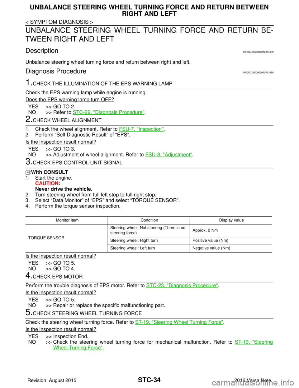
3.CHECK EPS CONTROL UNIT SIGNAL
With CONSULT
1. Start the engine.
CAUTION:
Never drive the vehicle.
2. Turn steering wheel from full left stop to full right stop.
3. Select “Data Monitor” of “EPS” and select “TORQUE SENSOR”.
4. Perform the torque sensor inspection.
Is the inspection result normal?
YES >> GO TO 5.
NO >> GO TO 4.
4.CHECK EPS MOTOR
Perform the trouble diagnosis of EPS motor. Refer to STC-23, "
Diagnosis Procedure".
Is the inspection result normal?
YES >> GO TO 5.
NO >> Repair or replace the specific malfunctioning part.
5.CHECK STEERING WHEEL TURNING FORCE
Check the steering wheel turning force. Refer to ST-19, "
Steering Wheel Turning Force".
Is the inspection result normal?
YES >> Inspection End.
NO >> Check the steering wheel turning force for mechanical malfunction. Refer to ST-19, "
Steering
Wheel Turning Force".
Monitor item ConditionDisplay value
TORQUE SENSOR Steering wheel: Not st
eering (There is no
steering force) Approx. 0 Nm
Steering wheel: Right turn Positive value (Nm)
Steering wheel: Left turn Negative value (Nm)
Revision: August 2015 2016 Versa Note
cardiagn.com
Page 3219 of 3641

UNBALANCE STEERING WHEEL TURNING FORCE (TORQUE VARIATION)
STC-35
< SYMPTOM DIAGNOSIS >
C
D E
F
H I
J
K L
M A
B
STC
N
O P
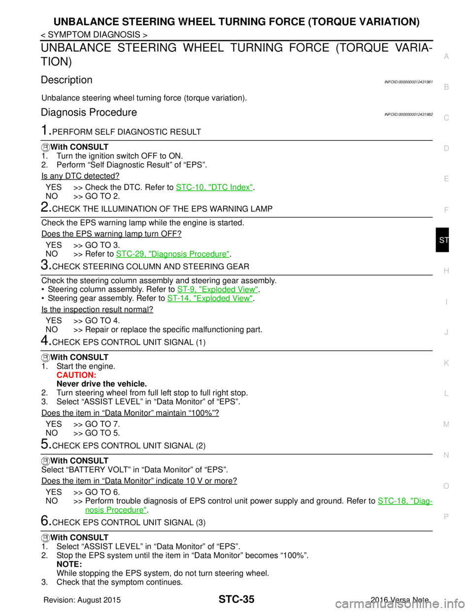
UNBALANCE STEERING WHEEL TU RNING FORCE (TORQUE VARIA-
TION)
DescriptionINFOID:0000000012431981
Unbalance steering wheel turning force (torque variation).
Diagnosis ProcedureINFOID:0000000012431982
1.PERFORM SELF DIAGNOSTIC RESULT
With CONSULT
1. Turn the ignition switch OFF to ON.
2. Perform “Self Diagnostic Result” of “EPS”.
Is any DTC detected?
YES >> Check the DTC. Refer to STC-10, "DTC Index".
NO >> GO TO 2.
2.CHECK THE ILLUMINATION OF THE EPS WARNING LAMP
Check the EPS warning lamp while the engine is started.
Does the EPS warning lamp turn OFF?
YES >> GO TO 3.
NO >> Refer to STC-29, "
Diagnosis Procedure".
3.CHECK STEERING COLU MN AND STEERING GEAR
Check the steering column assembly and steering gear assembly.
• Steering column assembly. Refer to ST-9, "
Exploded View".
• Steering gear assembly. Refer to ST-14, "
Exploded View".
Is the inspection result normal?
YES >> GO TO 4.
NO >> Repair or replace the specific malfunctioning part.
4.CHECK EPS CONTROL UNIT SIGNAL (1)
With CONSULT
1. Start the engine. CAUTION:
Never drive the vehicle.
2. Turn steering wheel from full left stop to full right stop.
3. Select “ASSIST LEVEL” in “Data Monitor” of “EPS”.
Does the item in
“Data Monitor” maintain “100%”?
YES >> GO TO 7.
NO >> GO TO 5.
5.CHECK EPS CONTROL UNIT SIGNAL (2)
With CONSULT
Select “BATTERY VOLT” in “Data Monitor” of “EPS”.
Does the item in
“Data Monitor” indicate 10 V or more?
YES >> GO TO 6.
NO >> Perform trouble diagnosis of EPS control unit power supply and ground. Refer to STC-18, "
Diag-
nosis Procedure".
6.CHECK EPS CONTROL UNIT SIGNAL (3)
With CONSULT
1. Select “ASSIST LEVEL” in “Data Monitor” of “EPS”.
2. Stop the EPS system until the item in “Data Monitor” becomes “100%”. NOTE:
While stopping the EPS system, do not turn steering wheel.
3. Check that the symptom continues.
Revision: August 2015 2016 Versa Note
cardiagn.com