2016 NISSAN NOTE stop start
[x] Cancel search: stop startPage 2336 of 3641

ENGINE MAINTENANCEMA-21
< PERIODIC MAINTENANCE >
C
DE
F
G H
I
J
K L
M B
MA
N
O A
WARNING:
• Be careful not to burn yoursel
f, as engine oil may be hot.
• When checking engine oil pressure, sh ift selector should be in the "P" (Park) or "N" (Neutral) posi-
tion, and apply parking brake securely.
1. Check engine oil level.
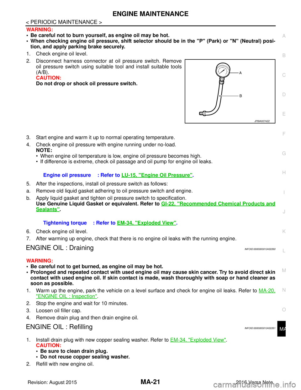
2. Disconnect harness connector at oil pressure switch. Remove oil pressure switch using suitable tool and install suitable tools
(A/B).
CAUTION:
Do not drop or shock oil pressure switch.
3. Start engine and warm it up to normal operating temperature.
4. Check engine oil pressure with engine running under no-load. NOTE:
• When engine oil temperature is low, engine oil pressure becomes high.
• If difference is extreme, check oil passage and oil pump for engine oil leaks.
5. After the inspections, install oil pressure switch as follows:
a. Remove old liquid gasket adhering to oil pressure switch and engine.
b. Apply liquid gasket and tighten oil pressure switch to specification. Use Genuine Liquid Gasket or equivalent. Refer to GI-22, "
Recommended Chemical Products and
Sealants".
6. Check engine oil level.
7. After warming up engine, check that there is no engine oil leaks with the running engine.
ENGINE OIL : DrainingINFOID:0000000012432260
WARNING:
• Be careful not to get burned, as engine oil may be hot.
• Prolonged and repeated contact with used engine oil may cause skin cancer. Try to avoid direct skin
contact with used engine oil. If skin contact is made, wash thorough ly with soap or hand cleaner as
soon as possible.
1. Warm up the engine, park the vehicle on a level surface and check for engine oil leaks. Refer to MA-20,
"ENGINE OIL : Inspection".
2. Stop the engine and wait for 10 minutes.
3. Loosen oil filler cap.
4. Remove drain plug and then drain engine oil.
ENGINE OIL : RefillingINFOID:0000000012432261
1. Install drain plug with new copper sealing washer. Refer to EM-34, "Exploded View".
CAUTION:
• Be sure to clean drain plug.
• Do not reuse copper sealing washer.
2. Refill with new engine oil.
JPBIA0074ZZ
Engine oil pressure : Refer to LU-15, "Engine Oil Pressure".
Tightening torque : Refer to EM-34, "
Exploded View".
Revision: August 2015 2016 Versa Note
cardiagn.com
Page 2342 of 3641

CHASSIS AND BODY MAINTENANCEMA-27
< PERIODIC MAINTENANCE >
C
DE
F
G H
I
J
K L
M B
MA
N
O A
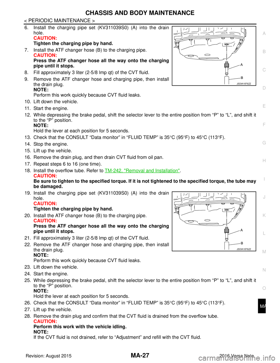
6. Install the charging pipe set (KV311039S0) (A) into the drain
hole.
CAUTION:
Tighten the charging pipe by hand.
7. Install the ATF changer hose (B) to the charging pipe. CAUTION:
Press the ATF changer hose all the way onto the charging
pipe until it stops.
8. Fill approximately 3 liter (2-5 /8 lmp qt) of the CVT fluid.
9. Remove the ATF changer hose and charging pipe, then install the drain plug.
NOTE:
Perform this work quickly because CVT fluid leaks.
10. Lift down the vehicle.
11. Start the engine.
12. While depressing the brake pedal, shift the selector leve r to the entire position from “P” to “L”, and shift it
to the “P” position.
NOTE:
Hold the lever at each position for 5 seconds.
13. Check that the CONSULT “Data monitor” in “FLUID TEMP” is 35°C (95°F) to 45 °C (113 °F).
14. Stop the engine.
15. Lift up the vehicle.
16. Remove the drain plug, and then drain CVT fluid from oil pan.
17. Repeat steps 6 to 16 (one time).
18. Install the overflow tube. Refer to TM-242, "
Removal and Installation".
CAUTION:
Be sure to tighten to the specified torque. If it is not tightened to the specified torque, the tube may
be damaged.
19. Install the charging pipe set (KV311039S0) (A) into the drain hole.
CAUTION:
Tighten the charging pipe by hand.
20. Install the ATF changer hose (B) to the charging pipe. CAUTION:
Press the ATF changer hose all the way onto the charging
pipe until it stops.
21. Fill approximately 3 liter (2-5 /8 lmp qt) of the CVT fluid.
22. Remove the ATF changer hose and charging pipe, then install the drain plug.
NOTE:
Perform this work quickly because CVT fluid leaks.
23. Lift down the vehicle.
24. Start the engine.
25. While depressing the brake pedal, shift the selector leve r to the entire position from “P” to “L”, and shift it
to the “P” position.
NOTE:
Hold the lever at each position for 5 seconds.
26. Check that the CONSULT “Data monitor” in “FLUID TEMP” is 35°C (95°F) to 45 °C (113 °F).
27. Lift up the vehicle.
28. Remove the drain plug and confirm that the CV T fluid is drained from the overflow tube.
CAUTION:
Perform this work with the vehicle idling.
NOTE:
If the CVT fluid is not drained, refer to “Adjustment” and refill with the CVT fluid.
JSDIA1876ZZ
JSDIA1876ZZ
Revision: August 2015 2016 Versa Note
cardiagn.com
Page 2343 of 3641

MA-28
< PERIODIC MAINTENANCE >
CHASSIS AND BODY MAINTENANCE
29. When the flow of CVT fluid slows to a drip, tighten the drain plug to the specified torque. TM-242,
"Removal and Installation".
CAUTION:
Never reuse drain plug gasket.
30. Lift down the vehicle.
31. Select “Work Support” in “TRANSMISSION” using CONSULT.
32. Select “CONFORM CVTF DETERIORTN”.
33. Select “Erase”.
34. Stop the engine.
CVT FLUID : AdjustmentINFOID:0000000012432269
CAUTION:
• Use only Genuine NISSAN CVT Fluid NS-3. Using transmission fluid other than Genuine NISSAN
CVT Fluid NS-3 will damage the CVT, which is not covered by the (NISSAN new vehicle limited) war-
ranty.
• During adjustment of the CVT fluid level, check CO NSULT so that the oil temperature may be main-
tained from 35 to 45 °C (95 to 113 °F).
• Use caution when looking into the drain hole as th ere is a risk of dripping fluid entering the eye.
1. Check that the selector lever is in the “P ” position, then completely engage the parking brake.
2. Start the engine.
3. Adjust the CVT fluid temperature to be approximately 40 °C (104° F).
NOTE:
The CVT fluid is largely affected by temperature. Therefore be sure to use CONSULT and check the
“FLUID TEMP” under “TRANSMISSION” in “Data Monitor” while adjusting.
4. While depressing the brake pedal, shift the selector lever to the entire position from “P” to “L”, and shift it to the “P” position.
NOTE:
Hold the lever at each position for 5 seconds.
5. Lift up the vehicle.
6. Check that there is no CVT fluid leakage.
7. Remove the drain plug. Refer to TM-242, "
Removal and Installation".
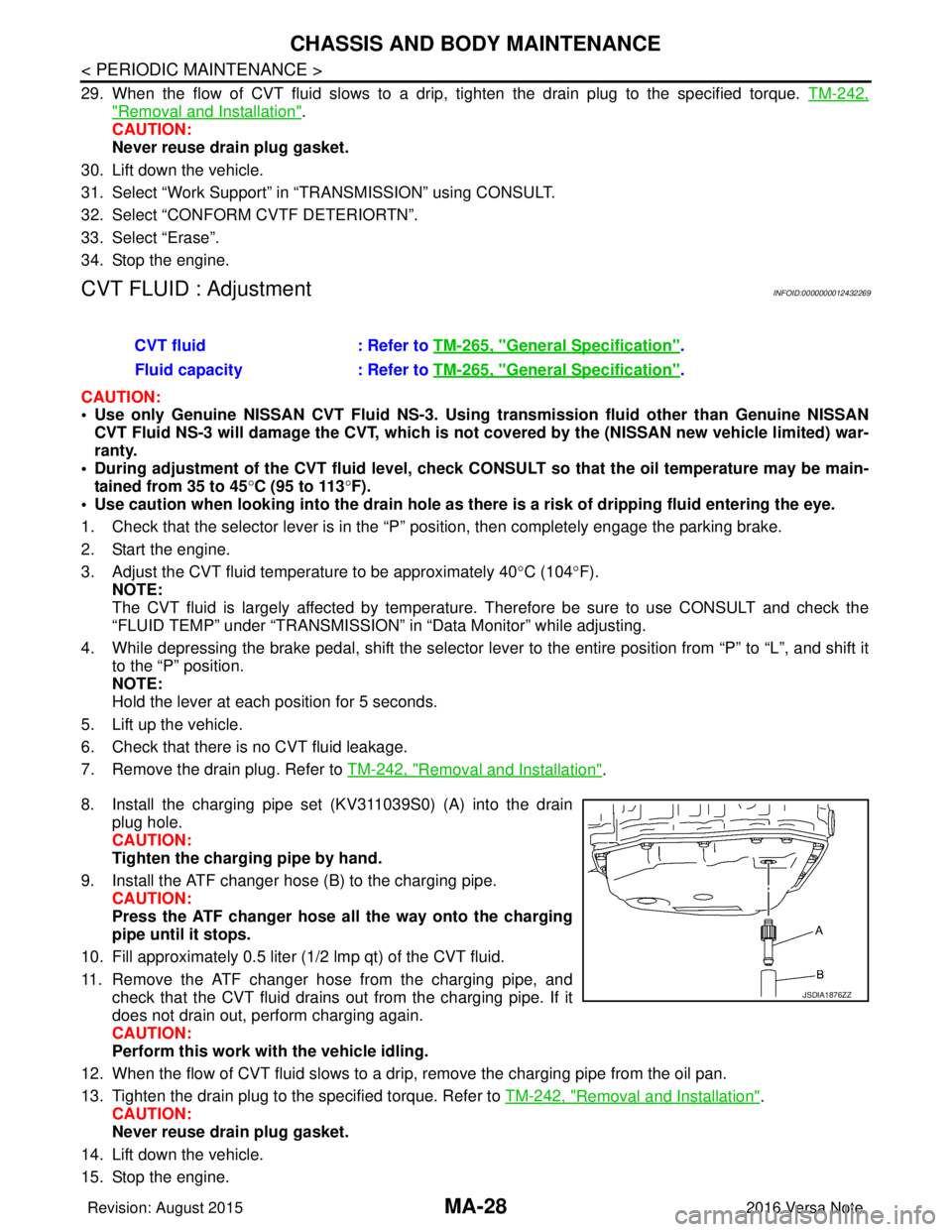
8. Install the charging pipe set (KV311039S0) (A) into the drain plug hole.
CAUTION:
Tighten the charging pipe by hand.
9. Install the ATF changer hose (B) to the charging pipe. CAUTION:
Press the ATF changer hose all the way onto the charging
pipe until it stops.
10. Fill approximately 0.5 liter (1/2 lmp qt) of the CVT fluid.
11. Remove the ATF changer hose from the charging pipe, and check that the CVT fluid drains out from the charging pipe. If it
does not drain out, perform charging again.
CAUTION:
Perform this work with the vehicle idling.
12. When the flow of CVT fluid slows to a drip, remove the charging pipe from the oil pan.
13. Tighten the drain plug to the specified torque. Refer to TM-242, "
Removal and Installation".
CAUTION:
Never reuse drain plug gasket.
14. Lift down the vehicle.
15. Stop the engine. CVT fluid
: Refer to TM-265, "
General Specification".
Fluid capacity : Refer to TM-265, "
General Specification".
JSDIA1876ZZ
Revision: August 2015 2016 Versa Note
cardiagn.com
Page 2346 of 3641

CHASSIS AND BODY MAINTENANCEMA-31
< PERIODIC MAINTENANCE >
C
DE
F
G H
I
J
K L
M B
MA
N
O A
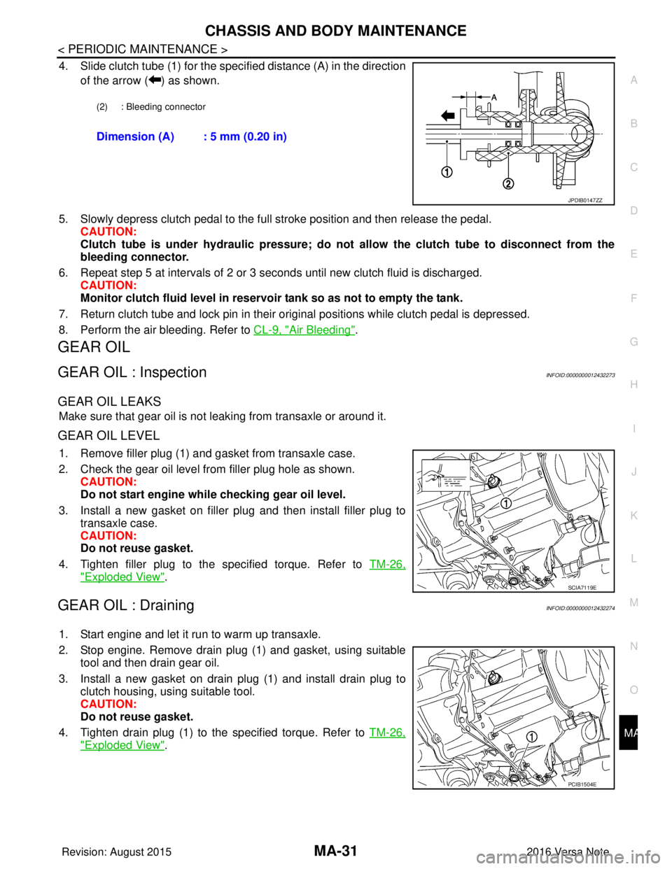
4. Slide clutch tube (1) for the specified distance (A) in the direction
of the arrow ( ) as shown.
5. Slowly depress clutch pedal to the full stroke position and then release the pedal. CAUTION:
Clutch tube is under hydraulic pressure; do not allow the clutch tube to disconnect from the
bleeding connector.
6. Repeat step 5 at intervals of 2 or 3 seconds until new clutch fluid is discharged. CAUTION:
Monitor clutch fluid level in reservoir tank so as not to empty the tank.
7. Return clutch tube and lock pin in their original positions while clutch pedal is depressed.
8. Perform the air bleeding. Refer to CL-9, "
Air Bleeding".
GEAR OIL
GEAR OIL : InspectionINFOID:0000000012432273
GEAR OIL LEAKS
Make sure that gear oil is not leaking from transaxle or around it.
GEAR OIL LEVEL
1. Remove filler plug (1) and gasket from transaxle case.
2. Check the gear oil level from filler plug hole as shown.
CAUTION:
Do not start engine whil e checking gear oil level.
3. Install a new gasket on filler plug and then install filler plug to transaxle case.
CAUTION:
Do not reuse gasket.
4. Tighten filler plug to the specified torque. Refer to TM-26,
"Exploded View".
GEAR OIL : DrainingINFOID:0000000012432274
1. Start engine and let it run to warm up transaxle.
2. Stop engine. Remove drain plug (1) and gasket, using suitable
tool and then drain gear oil.
3. Install a new gasket on drain plug (1) and install drain plug to clutch housing, using suitable tool.
CAUTION:
Do not reuse gasket.
4. Tighten drain plug (1) to the specified torque. Refer to TM-26,
"Exploded View".
(2) : Bleeding connector
Dimension (A) : 5 mm (0.20 in)
JPDIB0147ZZ
SCIA7119E
PCIB1504E
Revision: August 2015 2016 Versa Note
cardiagn.com
Page 2484 of 3641

MIR-10
< SYMPTOM DIAGNOSIS >
SQUEAK AND RATTLE TROUBLE DIAGNOSES
INSTRUMENT PANEL
Most incidents are caused by contact and movement between:
1. Cluster lid A and the instrument panel
2. Acrylic lens and combination meter housing
3. Instrument panel to front pillar finisher
4. Instrument panel to windshield
5. Instrument panel pins
6. Wiring harnesses behind the combination meter
7. A/C defroster duct and duct joint
These incidents can usually be located by tapping or moving the components to duplicate the noise or by
pressing on the components while driving to stop the noise. Most of these incidents can be repaired by apply-
ing felt cloth tape or silicone spray (in hard to reach areas). Urethane pads can be used to insulate wiring har-
ness.
CAUTION:
Do not use silicone spray to isolate a squeak or rattle. If you saturate the ar ea with silicone, you will
not be able to recheck the repair.
CENTER CONSOLE
Components to pay attention to include:
1. Shift selector assembly cover to finisher
2. A/C control unit and cluster lid C
3. Wiring harnesses behind audio and A/C control unit
The instrument panel repair and isolation pr ocedures also apply to the center console.
DOORS
Pay attention to the:
1. Finisher and inner panel making a slapping noise
2. Inside handle escutcheon to door finisher
3. Wiring harnesses tapping
4. Door striker out of alignment causing a popping noise on starts and stops
Tapping or moving the components or pressing on them wh ile driving to duplicate the conditions can isolate
many of these incidents. You can usually insulate the areas with felt cloth tape or insulator foam blocks from
the NISSAN Squeak and Rattle Kit (J-50397) to repair the noise.
TRUNK
Trunk noises are often caused by a loose jack or loose items put into the trunk by the owner.
In addition look for:
1. Trunk lid bumpers out of adjustment
2. Trunk lid striker out of adjustment
3. The trunk lid torsion bars knocking together
4. A loose license plate or bracket
Most of these incidents can be repaired by adjusting, se curing or insulating the item(s) or component(s) caus-
ing the noise.
SUNROOF/HEADLINING
Noises in the sunroof/headlining area c an often be traced to one of the following:
1. Sunroof lid, rail, linkage or seals making a rattle or light knocking noise
2. Sun visor shaft shaking in the holder
3. Front or rear windshield touching headlining and squeaking
Again, pressing on the components to stop the noise while duplicating the conditions can isolate most of these
incidents. Repairs usually consist of insulating with felt cloth tape.
OVERHEAD CONSOLE (FRONT AND REAR)
Overhead console noises are often caused by the c onsole panel clips not being engaged correctly. Most of
these incidents are repaired by pushing up on the c onsole at the clip locations until the clips engage.
In addition look for:
Revision: August 2015 2016 Versa Note
cardiagn.com
Page 2509 of 3641
![NISSAN NOTE 2016 Service Repair Manual PCS-6
< SYSTEM DESCRIPTION >[IPDM E/R]
SYSTEM
RELAY CONTROL SYSTEM : Fail-safe
INFOID:0000000012433269
CAN COMMUNICATION CONTROL
When CAN communication with ECM and BCM is impossible, IPDM E/R perform NISSAN NOTE 2016 Service Repair Manual PCS-6
< SYSTEM DESCRIPTION >[IPDM E/R]
SYSTEM
RELAY CONTROL SYSTEM : Fail-safe
INFOID:0000000012433269
CAN COMMUNICATION CONTROL
When CAN communication with ECM and BCM is impossible, IPDM E/R perform](/manual-img/5/57363/w960_57363-2508.png)
PCS-6
< SYSTEM DESCRIPTION >[IPDM E/R]
SYSTEM
RELAY CONTROL SYSTEM : Fail-safe
INFOID:0000000012433269
CAN COMMUNICATION CONTROL
When CAN communication with ECM and BCM is impossible, IPDM E/R performs fail-safe control. After CAN
communication recovers normally, it also returns to normal control.
If No CAN Communication Is Available With ECM
If No CAN Communication Is Available With BCM
Control relay Input/outputTransmit unit Control part Reference page
• Headlamp low relay
• Headlamp high relay • Low beam request signal
• High beam request signal
BCM (CAN)
• Headlamp LO
• Headlamp HI EXL-8
Tail lamp relay
Position light request signal BCM (CAN) •Parking lamp
• Side marker lamp
• License plate lamp
• Tail lamp
EXL-11
Illuminations
INL-9
• Front wiper relay
• Front wiper high relayFront wiper request signal BCM (CAN)
Front wiper motorWW-8Front wiper stop position sig-
nal Front wiper motor
Starter control relay Starter control relay signal BCM (CAN)
Starter motorSTR-8
(without Intelli-
gent Key)
STR-9
(with Intelligent
Key)
Transmission range switch
signal (CVT models)
Transmission range
switch
Clutch interlock switch signal
(M/T models) Clutch interlock switch
• Cooling fan low relay
• Cooling fan high relay Cooling fan speed request sig-
nal
ECM (CAN)
Cooling fan EC-38
A/C relayA/C compressor request sig-
nal
ECM (CAN)A/C compressor
(Magnet clutch)
HAC-11
Ignition relay-1Ignition switch ON signal BCM (CAN)
Each control unit,
sensor, actuator and
relay (Ignition power
supply) EC-35Vehicle speed signal (Meter)
Combination meter
(CAN)
Push-button ignition switch
signal Push-button ignition
switch
Control part
Fail-safe operation
Cooling fan • The cooling fan relay turn ON when the ignition switch is turned ON (Cooling fan HI operation)
• The cooling fan relay turn OFF when the ignition switch is turned OFF
A/C compressor A/C relay OFF
Generator Outputs the power generation command signal (PWM signal) 0%
Control part Fail-safe operation
Headlamp • Turns ON the headlamp low relay when the ignition switch is turned ON
• Turns OFF the headlamp low relay when the ignition switch is turned OFF
• Headlamp high relay OFF
•Parking lamp
• Side marker lamp
• License plate lamp
• Illumination
• Tail lamp • Turns ON the tail lamp relay when the ignition switch is turned ON
• Turns OFF the tail lamp relay when the ignition switch is turned OFF
Revision: August 2015
2016 Versa Note
cardiagn.com
Page 2510 of 3641
![NISSAN NOTE 2016 Service Repair Manual PCS
SYSTEMPCS-7
< SYSTEM DESCRIPTION > [IPDM E/R]
C
D
E
F
G H
I
J
K L
B A
O P
N
IGNITION RELAY MALFUNCTION DETECTION FUNCTION
• IPDM E/R monitors the voltage at the contact circuit and excitation co NISSAN NOTE 2016 Service Repair Manual PCS
SYSTEMPCS-7
< SYSTEM DESCRIPTION > [IPDM E/R]
C
D
E
F
G H
I
J
K L
B A
O P
N
IGNITION RELAY MALFUNCTION DETECTION FUNCTION
• IPDM E/R monitors the voltage at the contact circuit and excitation co](/manual-img/5/57363/w960_57363-2509.png)
PCS
SYSTEMPCS-7
< SYSTEM DESCRIPTION > [IPDM E/R]
C
D
E
F
G H
I
J
K L
B A
O P
N
IGNITION RELAY MALFUNCTION DETECTION FUNCTION
• IPDM E/R monitors the voltage at the contact circuit and excitation coil circuit of the ignition relay inside it.
• IPDM E/R judges the ignition relay error if the voltage differs between the contact circuit and the excitation
coil circuit.
• If the ignition relay cannot turn OFF due to contact seizure, it activates the tail lamp relay for 10 minutes to
alert the user to the ignition relay malfunction when the ignition switch is turned OFF.
NOTE:
The tail lamp turns OFF when the ignition switch is turned ON.
FRONT WIPER CONTROL
IPDM E/R detects front wiper stop posit ion by a front wiper auto stop signal.
When a front wiper auto stop signal is in the conditions listed below, IPDM E/R stops power supply to wiper
after repeating a front wiper 10 second activation and 20 second stop five times.
NOTE:
This operation status can be confirmed on the IPDM E/ R “Data Monitor” that displays “BLOCK” for the item
“WIP PROT” while the wiper is stopped.
STARTER MOTOR PROTECTION FUNCTION
IPDM E/R turns OFF the starter control relay to protect the starter motor when the starter control relay remains
active for 90 seconds.
POWER CONSUMPTIO N CONTROL SYSTEM
Front wiper motor • The status just before activation of fail-safe control is maintained until the ignition switch is
turned OFF while the front wiper is operating at LO or HI speed.
• The wiper is operated at LO speed until the ignition switch is turned OFF if the fail-safe control is activated while the front wiper is set in the INT mode and the front wiper motor is operating.
• Returns automatically wiper to stop position when ignition switch is turned ON if fail-safe control
is activated while front wiper motor is operated and wiper stop in the other position than stop
position.
Front fog lamp (if equipped) Front fog lamp relay OFF
Horn Horn OFF
Ignition relay The status just before activation of fail-safe is maintained.
Starter motor Starter control relay OFF
Control part
Fail-safe operation
DTCIgnition switch Ignition relayTail lamp relay
—O NON—
—O FFO FF—
B2098: IGN RELAY ON OFFONON (10 minutes)
B2099: IGN RELAY OFF ONOFF —
Ignition switch Front wiper switch Auto stop signal
ON OFF
Front wiper stop position signal cannot be
input 10 seconds.
ON The signal does not change for 10 seconds.
Revision: August 2015 2016 Versa Note
cardiagn.com
Page 2511 of 3641
![NISSAN NOTE 2016 Service Repair Manual PCS-8
< SYSTEM DESCRIPTION >[IPDM E/R]
SYSTEM
POWER CONSUMPTION CONTROL SY STEM : System Description
INFOID:0000000012433270
SYSTEM DIAGRAM
DESCRIPTION
Outline
• IPDM E/R incorporates a power consum NISSAN NOTE 2016 Service Repair Manual PCS-8
< SYSTEM DESCRIPTION >[IPDM E/R]
SYSTEM
POWER CONSUMPTION CONTROL SY STEM : System Description
INFOID:0000000012433270
SYSTEM DIAGRAM
DESCRIPTION
Outline
• IPDM E/R incorporates a power consum](/manual-img/5/57363/w960_57363-2510.png)
PCS-8
< SYSTEM DESCRIPTION >[IPDM E/R]
SYSTEM
POWER CONSUMPTION CONTROL SY STEM : System Description
INFOID:0000000012433270
SYSTEM DIAGRAM
DESCRIPTION
Outline
• IPDM E/R incorporates a power consumption control function that reduces the power consumption accord-
ing to the vehicle status.
• IPDM E/R changes its status (control mode) with the sleep wake up signal received from BCM via CAN com- munication.
Normal mode (wake-up)- CAN communication is normally performed with other control units.
- Individual unit control by IPDM E/R is normally performed.
Low power consumption mode (sleep)- Low power consumption control is active.
- CAN transmission is stopped.
Sleep Mode Activation
• IPDM E/R judges that the sleep-ready conditions are fulfilled when the ignition switch is OFF and none of theconditions below are present. Then it transmits a sleep-ready signal (ready) to BCM via CAN communica-
tion:
- Outputting signals to actuators
- Switches or relays operating
- Output requests are being received from control units via CAN communication.
• IPDM E/R stops CAN communication and enters the low power consumption mode when it receives a sleep
wake up signal (sleep) from BCM and the sleep-ready conditions are fulfilled.
Wake-up Operation
• IPDM E/R changes from the low power consumption mode to the normal mode when it receives a sleep
wake-up signal (wake up) from BCM or any of the following conditions is fulfilled. In addition, it transmits a
sleep-ready signal (not-ready) to BCM via CAN communication to report the CAN communication start:
- Ignition switch ON
- An output request is received from a control unit via CAN communication.
AWMIA1529GB
Revision: August 2015 2016 Versa Note
cardiagn.com