2016 NISSAN NOTE stop start
[x] Cancel search: stop startPage 2044 of 3641

REFRIGERANTHA-19
< PERIODIC MAINTENANCE >
C
DE
F
G H
J
K L
M A
B
HA
N
O P
4. Press UV lamp switch (5) and check A/C system for re frigerant leaks. (Where refrigerant leaks occur, flu-
orescent leak detection dye appears green in color.)
WARNING:
Do not look directly into UV lamp light source.
NOTE:
• For continuous operating time of UV lamp, fo llow the manufacturer’s operating instructions.
• Illuminate pipe joints from different angles using UV lamp to check for leaks.
• Use a mirror in areas that are di fficult to see to check for leaks.
• Refrigerant leaks from the evaporator can be detected by soaking a cotton swab or similar material with
drain hose water and illuminating it using the UV lamp.
• Dust, dirt, and packing material adhesives used for condenser, evaporator, and other components may fluoresce. Be careful not to misidentify leaks.
5. Repair or replace parts where refrigerant lea ks occur and wipe off fluorescent leak detection dye.
NOTE:
Completely wipe off fluorescent leak detection dye from gaps between parts, screw threads, and other
components using a cotton swab or similar material.
6. Use a UV lamp to check that no fluorescent leak detection dye remains after finishing work. WARNING:
Do not look directly into UV lamp light source.
NOTE:
• For continuous operating time of UV lamp, fo llow the manufacturer’s operating instructions.
• Dust, dirt, and packing material adhesives used for condenser, evaporator, and other components may
fluoresce. Be careful not to misidentify leaks.
CHECK REFRIGERANT LEAKS USING ELECTRONIC LEAK DETECTOR
WARNING:
Do not check for refrigerant leaks while the engine is running.
CAUTION:
Be careful of the following items so that in accurate checks or misidentifications are avoided.
• Do not allow refrigerant vapor, shop chemical vapors, cigarette smoke or other contaminates around the vehicle.
• Always check refrigerant leaks in a low air flow en vironment so that refrigerant may not disperse.
1. Stop the engine.
2. Connect recovery/recycling/recharging equipment or manifold gauge set to the A/C service valves.
3. Check that A/C refrigerant pressure is 345 kPa (3.52 kg/cm
2, 50 psi) or more when temperature is 16 °C
(61 °F) or more. When pressure is lower than the specified value, recycle refrigerant completely and
recharge refrigerant to the specified level.
NOTE:
Leaks may not be detected if A/C refriger ant pressure is 345 kPa (3.52 kg/cm
2, 50 psi) or less when tem-
perature is less than 16° C (61°F).
4. Clean the area where the refrigerant leak check is performed and check for refrigerant leaks along all sur- faces of pipe connections and A/C system co mponents using electronic leak detector probe.
CAUTION:
• Continue checking once leaks are found. Always co ntinue and complete checking along all pipe
connections and A/C system comp onents for additional leaks.
• When leaks are detected, clean leak ar ea using compressed air and re-check.
• When checking the evaporator for leaks, always clean inside of drain hose so that the probe sur-
face may not be exposed to water or dirt.
NOTE:
• Always check for leaks starting from the high-pressure side and continue to the low-pressure side.
• When checking the evaporator for leaks, operate blower motor for 15 minut\
es or more at the maximum speed while the engine is stopped. Insert electronic leak detector probe into drain hose and hold for 10
minutes or more.
• When disconnecting shut-off valve that is connected to A/C service valve, always evacuate remaining
refrigerant so that misidentification can be avoided.
5. Repair or replace parts where refrigerant leaks occur.
6. Start the engine and set A/C control in the following conditions. • A/C switch: ON
Revision: August 2015 2016 Versa Note
cardiagn.com
Page 2045 of 3641

HA-20
< PERIODIC MAINTENANCE >
REFRIGERANT
• Air flow: VENT (ventilation)
• Intake door position: Recirculation
• Temperature setting: Full cold
• Blower speed: Maximum
7. Run the engine at approximately 1,500 rpm for two minutes or more.
8. Stop the engine. Check for refrigerant leaks. Go to step 4. WARNING:
Be careful not to get burned when the engine is hot.
NOTE:
• Start refrigerant leak check immediately after the engine is stopped.
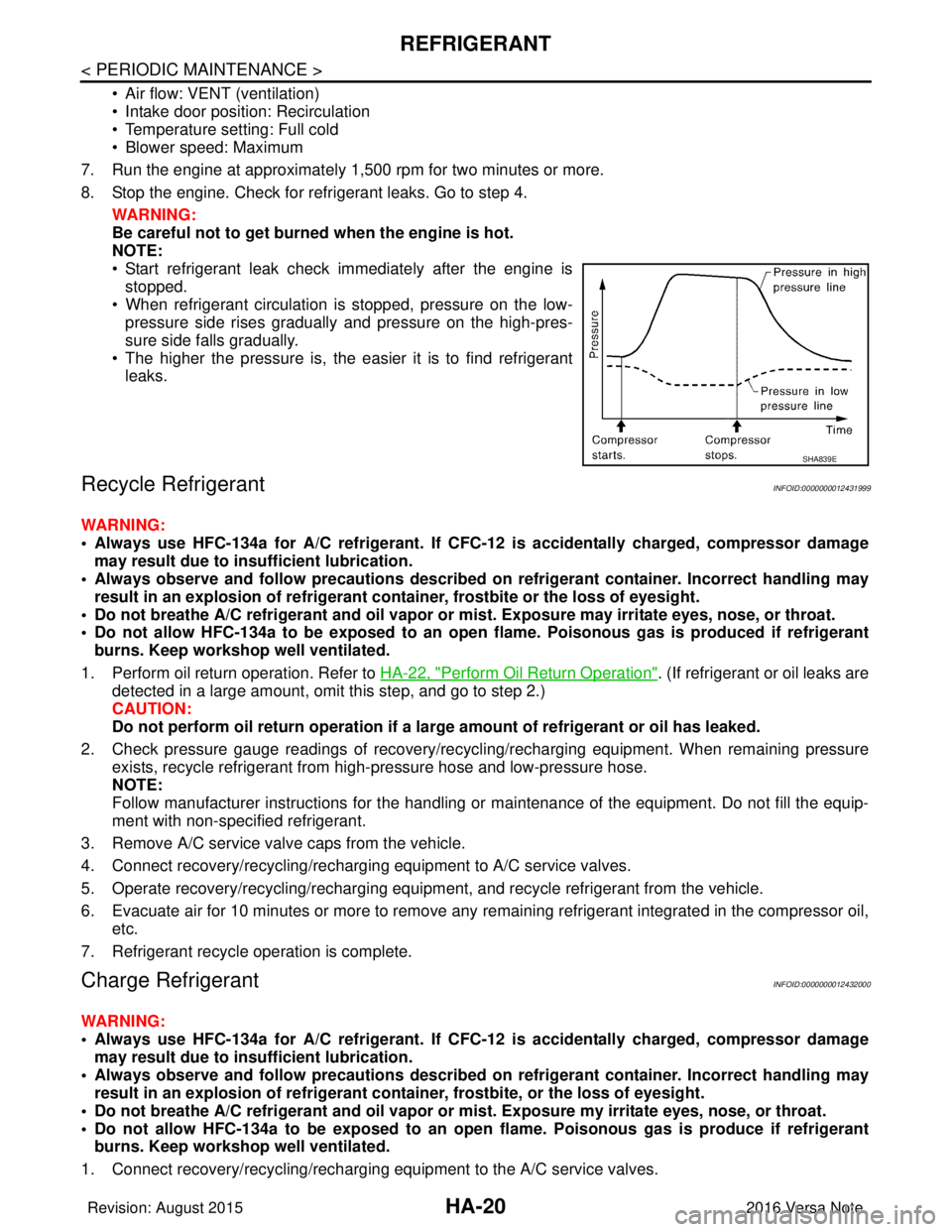
• When refrigerant circulation is stopped, pressure on the low- pressure side rises gradually and pressure on the high-pres-
sure side falls gradually.
• The higher the pressure is, the easier it is to find refrigerant leaks.
Recycle RefrigerantINFOID:0000000012431999
WARNING:
• Always use HFC-134a for A/C refrigerant. If CFC- 12 is accidentally charged, compressor damage
may result due to in sufficient lubrication.
• Always observe and follow precaution s described on refrigerant container. Incorrect handling may
result in an explosion of refrigerant container, frostbite or the loss of eyesight.
• Do not breathe A/C refrigerant and oil vapor or mi st. Exposure may irritate eyes, nose, or throat.
• Do not allow HFC-134a to be exposed to an open flame. Poisonous gas is produced if refrigerant
burns. Keep workshop well ventilated.
1. Perform oil return operation. Refer to HA-22, "
Perform Oil Return Operation". (If refrigerant or oil leaks are
detected in a large amount, omit this step, and go to step 2.)
CAUTION:
Do not perform oil return operation if a la rge amount of refrigerant or oil has leaked.
2. Check pressure gauge readings of recovery/recyc ling/recharging equipment. When remaining pressure
exists, recycle refrigerant from high-pressure hose and low-pressure hose.
NOTE:
Follow manufacturer instructions for the handling or maintenance of the equipment. Do not fill the equip-
ment with non-specified refrigerant.
3. Remove A/C service valve caps from the vehicle.
4. Connect recovery/recycling/recharging equipment to A/C service valves.
5. Operate recovery/recycling/recharging equipm ent, and recycle refrigerant from the vehicle.
6. Evacuate air for 10 minutes or more to remove any remaining refrigerant integrated in the compressor oil,
etc.
7. Refrigerant recycle operation is complete.
Charge RefrigerantINFOID:0000000012432000
WARNING:
• Always use HFC-134a for A/C refrigerant. If CFC- 12 is accidentally charged, compressor damage
may result due to in sufficient lubrication.
• Always observe and follow precaution s described on refrigerant container. Incorrect handling may
result in an explosion of refrigerant co ntainer, frostbite, or the loss of eyesight.
• Do not breathe A/C refrigerant and oil vapor or mi st. Exposure my irritate eyes, nose, or throat.
• Do not allow HFC-134a to be exposed to an open flame. Poisonous gas is produce if refrigerant burns. Keep workshop well ventilated.
1. Connect recovery/recycling/recharging equipment to the A/C service valves.
SHA839E
Revision: August 2015 2016 Versa Note
cardiagn.com
Page 2047 of 3641

HA-22
< PERIODIC MAINTENANCE >
OIL
OIL
DescriptionINFOID:0000000012432001
MAINTENANCE OF OIL LEVEL
The compressor oil circulates in the system together with the refrigerant. It is necessary to add oil to the com-
pressor when replacing A/C system components or when a large amount of refrigerant leaks from the system.
It is important to always maintain oil level within t he specified level. Otherwise, the following conditions may
occur.
• Insufficient oil amount: Stuck compressor
• Excessive oil amount: Insufficient cooling (caused by insufficient heat exchange)
InspectionINFOID:0000000012432002
If a compressor is malfunctioning (internal noise, insufficient cooling), check the compressor oil.
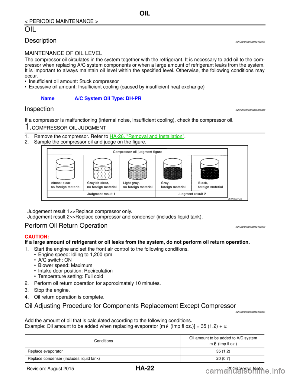
1.COMPRESSOR OIL JUDGMENT
1. Remove the compressor. Refer to HA-26, "
Removal and Installation".
2. Sample the compressor oil and judge on the figure.
Judgement result 1>>Replace compressor only.
Judgement result 2>>Replace compressor and condenser (includes liquid tank).
Perform Oil Retu rn OperationINFOID:0000000012432003
CAUTION:
If a large amount of refrigerant or oil leaks from the system, do not perform oil return operation.
1. Start the engine and set the front air control to the following conditions. • Engine speed: Idling to 1,200 rpm
• A/C switch: ON
• Blower speed: Maximum
• Intake door position: Recirculation
• Temperature setting: Full cold
2. Perform oil return operation for approximately 10 minutes.
3. Stop the engine.
4. Oil return operation is complete.
Oil Adjusting Procedure for Compon ents Replacement Except Compressor
INFOID:0000000012432004
Add the amount of oil that is calculated according to the following conditions.
Example: Oil amount to be added when replacing evaporator [m (Imp fl oz.)] = 35 (1.2) + α
Name A/C System Oil Type: DH-PR
JSIIA0927GB
Conditions
Oil amount to be added to A/C system
m (Imp fl oz.)
Replace evaporator 35 (1.2)
Replace condenser (includes liquid tank) 20 (0.7)
Revision: August 20152016 Versa Note
cardiagn.com
Page 2078 of 3641

IP-10
< SYMPTOM DIAGNOSIS >
SQUEAK AND RATTLE TROUBLE DIAGNOSES
INSTRUMENT PANEL
Most incidents are caused by contact and movement between:
1. Cluster lid A and the instrument panel
2. Acrylic lens and combination meter housing
3. Instrument panel to front pillar finisher
4. Instrument panel to windshield
5. Instrument panel pins
6. Wiring harnesses behind the combination meter
7. A/C defroster duct and duct joint
These incidents can usually be located by tapping or moving the components to duplicate the noise or by
pressing on the components while driving to stop the noise. Most of these incidents can be repaired by apply-
ing felt cloth tape or silicone spray (in hard to reach areas). Urethane pads can be used to insulate wiring har-
ness.
CAUTION:
Do not use silicone spray to isolate a squeak or rattle. If you saturate the ar ea with silicone, you will
not be able to recheck the repair.
CENTER CONSOLE
Components to pay attention to include:
1. Shift selector assembly cover to finisher
2. A/C control unit and cluster lid C
3. Wiring harnesses behind audio and A/C control unit
The instrument panel repair and isolation pr ocedures also apply to the center console.
DOORS
Pay attention to the:
1. Finisher and inner panel making a slapping noise
2. Inside handle escutcheon to door finisher
3. Wiring harnesses tapping
4. Door striker out of alignment causing a popping noise on starts and stops
Tapping or moving the components or pressing on them wh ile driving to duplicate the conditions can isolate
many of these incidents. You can usually insulate the areas with felt cloth tape or insulator foam blocks from
the NISSAN Squeak and Rattle Kit (J-50397) to repair the noise.
TRUNK
Trunk noises are often caused by a loose jack or loose items put into the trunk by the owner.
In addition look for:
1. Trunk lid bumpers out of adjustment
2. Trunk lid striker out of adjustment
3. The trunk lid torsion bars knocking together
4. A loose license plate or bracket
Most of these incidents can be repaired by adjusting, se curing or insulating the item(s) or component(s) caus-
ing the noise.
SUNROOF/HEADLINING
Noises in the sunroof/headlining area c an often be traced to one of the following:
1. Sunroof lid, rail, linkage or seals making a rattle or light knocking noise
2. Sun visor shaft shaking in the holder
3. Front or rear windshield touching headlining and squeaking
Again, pressing on the components to stop the noise while duplicating the conditions can isolate most of these
incidents. Repairs usually consist of insulating with felt cloth tape.
OVERHEAD CONSOLE (FRONT AND REAR)
Overhead console noises are often caused by the c onsole panel clips not being engaged correctly. Most of
these incidents are repaired by pushing up on the c onsole at the clip locations until the clips engage.
In addition look for:
Revision: August 2015 2016 Versa Note
cardiagn.com
Page 2107 of 3641
![NISSAN NOTE 2016 Service Repair Manual DIAGNOSIS SYSTEM (BCM) (WITH INTELLIGENT KEY SYSTEM)
INL-13
< SYSTEM DESCRIPTION >
C
D E
F
G H
I
J
K
M A
B
INL
N
O P
ACTIVE TEST
BRAKE SW 2 [On/Off] Indicates condition of brake switch.
DETE/CANCL SW NISSAN NOTE 2016 Service Repair Manual DIAGNOSIS SYSTEM (BCM) (WITH INTELLIGENT KEY SYSTEM)
INL-13
< SYSTEM DESCRIPTION >
C
D E
F
G H
I
J
K
M A
B
INL
N
O P
ACTIVE TEST
BRAKE SW 2 [On/Off] Indicates condition of brake switch.
DETE/CANCL SW](/manual-img/5/57363/w960_57363-2106.png)
DIAGNOSIS SYSTEM (BCM) (WITH INTELLIGENT KEY SYSTEM)
INL-13
< SYSTEM DESCRIPTION >
C
D E
F
G H
I
J
K
M A
B
INL
N
O P
ACTIVE TEST
BRAKE SW 2 [On/Off] Indicates condition of brake switch.
DETE/CANCL SW [On/Off] ×Indicates condition of P (park) position.
SFT PN/N SW [On/Off] ×Indicates condition of P (park) or N (neutral) position.
UNLK SEN -DR [On/Off] ×Indicates condition of door unlock sensor.
PUSH SW -IPDM [On/Off] Indicates condition of push-button ignition switch received from IPDM E/R on
CAN communication line.
IGN RLY1 -F/B [On/Off] Indicates condition of ignition relay 1 received from IPDM E/R on CAN commu-
nication line.
DETE SW -IPDM [On/Off] Indicates condition of detent switch received from TCM on CAN communication
line.
SFT PN -IPDM [On/Off] Indicates condition of P (park) or N (neutral) position from TCM on CAN com-
munication line.
SFT P -MET [On/Off] Indicates condition of P (park) position from TCM on CAN communication line.
SFT N -MET [On/Off] Indicates condition of N (neutral) position from IPDM E/R on CAN communica-
tion line.
ENGINE STATE [Stop/Start/Crank/Run] ×Indicates condition of engine state from ECM on CAN communication line.
VEH SPEED 1 [mph/km/h] ×Indicates condition of vehicle speed si
gnal received from ABS on CAN commu-
nication line.
VEH SPEED 2 [mph/km/h] ×Indicates condition of vehicle speed signal received from combination meter on
CAN communication line.
DOOR STAT -DR [LOCK/READY/UNLK] ×Indicates condition of driver side door status.
DOOR STAT -AS [LOCK/READY/UNLK] ×Indicates condition of passenger side door status.
ID OK FLAG [Set/Reset] Indicates condition of Intelligent Key ID.
PRMT ENG STRT [Set/Reset] Indicates condition of engine start possibility.
RKE OPE COUN1 [0-19] ×When remote keyless entry receiver receives the signal transmitted while oper-
ating on Intelligent Key, the numerical value start changing.
RKE OPE COUN2 [0-19] ×When remote keyless entry receiver receives the signal transmitted while oper-
ating on Intelligent Key, the numerical value start changing.
RKE-LOCK [On/Off] Indicates condition of lock signal from Intelligent Key.
RKE-UNLOCK [On/Off] Indicates condition of unlock signal from Intelligent Key.
RKE-PANIC [On/Off] Indicates condition of panic signal from Intelligent Key.
RKE-MODE CHG [On/Off] Indicates condition of mode change signal from Intelligent Key.
Monitor Item [Unit]
Main Description
Test Item Description
INSIDE BUZZER This test is able to check combination meter warning chime operation [Take Out/Knob/Key/
Off].
LCD This test is able to check combination me
ter display information [Off/LK WN/OUTKEY/NO
KY/BATT/INSRT/SFT P/ROTAT/ID NG/B&P I/B&P N].
BATTERY SAVER This test is able to check battery saver operation [On/Off].
ENGINE SW ILLUMI This test is able to check push-button ignition switch START indicator operation [On/Off].
PUSH SWITCH INDICATOR This test is able to check push-button ignition switch indicator operation [On/Off].
INT LAMP This test is able to check interior room lamp operation [On/Off].
INDICATOR This test is able to check combination mete r warning lamp operation [KEY ON/KEY IND/Off].
FLASHER This test is able to check hazard lamp operation [LH/RH/Off].
OUTSIDE BUZZER This test is able to check Intelligent Key warning buzzer operation [On/Off].
HORN This test is able to check horn operation [On].
P RANGE This test is able to check CVT shift selector illumination operation [On/Off].
Revision: August 2015 2016 Versa Note
cardiagn.com
Page 2162 of 3641

SQUEAK AND RATTLE TROUBLE DIAGNOSESINT-11
< SYMPTOM DIAGNOSIS >
C
DE
F
G H
I
K L
M A
B
INT
N
O P
INSTRUMENT PANEL
Most incidents are caused by contact and movement between:
1. Cluster lid A and the instrument panel
2. Acrylic lens and combination meter housing
3. Instrument panel to front pillar finisher
4. Instrument panel to windshield
5. Instrument panel pins
6. Wiring harnesses behind the combination meter
7. A/C defroster duct and duct joint
These incidents can usually be located by tapping or moving the components to duplicate the noise or by
pressing on the components while driving to stop the noi se. Most of these incidents can be repaired by apply-
ing felt cloth tape or silicone spray (in hard to reach areas). Urethane pads can be used to insulate wiring har-
ness.
CAUTION:
Do not use silicone spray to isolate a squeak or ra ttle. If you saturate the area with silicone, you will
not be able to recheck the repair.
CENTER CONSOLE
Components to pay attention to include:
1. Shift selector assembly cover to finisher
2. A/C control unit and cluster lid C
3. Wiring harnesses behind audio and A/C control unit
The instrument panel repair and isolation pr ocedures also apply to the center console.
DOORS
Pay attention to the:
1. Finisher and inner panel making a slapping noise
2. Inside handle escutcheon to door finisher
3. Wiring harnesses tapping
4. Door striker out of alignment causing a popping noise on starts and stops
Tapping or moving the components or pressing on them while driving to duplicate the conditions can isolate
many of these incidents. You can usually insulate the ar eas with felt cloth tape or insulator foam blocks from
the NISSAN Squeak and Rattle Kit (J-50397) to repair the noise.
TRUNK
Trunk noises are often caused by a loose jack or loose items put into the trunk by the owner.
In addition look for:
1. Trunk lid bumpers out of adjustment
2. Trunk lid striker out of adjustment
3. The trunk lid torsion bars knocking together
4. A loose license plate or bracket
Most of these incidents can be repaired by adjusting, se curing or insulating the item(s) or component(s) caus-
ing the noise.
SUNROOF/HEADLINING
Noises in the sunroof/headlining area can often be traced to one of the following:
1. Sunroof lid, rail, linkage or seals making a rattle or light knocking noise
2. Sun visor shaft shaking in the holder
3. Front or rear windshield touching headlining and squeaking
Again, pressing on the components to stop the noise while duplicating the conditions can isolate most of these
incidents. Repairs usually consist of insulating with felt cloth tape.
OVERHEAD CONSOLE (FRONT AND REAR)
Overhead console noises are often caused by the cons ole panel clips not being engaged correctly. Most of
these incidents are repaired by pushing up on the c onsole at the clip locations until the clips engage.
In addition look for:
Revision: August 2015 2016 Versa Note
cardiagn.com
Page 2219 of 3641
![NISSAN NOTE 2016 Service Repair Manual LAN
SYSTEMLAN-31
< SYSTEM DESCRIPTION > [CAN]
C
D
E
F
G H
I
J
K L
B A
O P
N
Vehicle speed signal (ABS)
TR R R R R
Brake warning lamp signal TR
Detention switch signal TR
Front wiper stop position sign NISSAN NOTE 2016 Service Repair Manual LAN
SYSTEMLAN-31
< SYSTEM DESCRIPTION > [CAN]
C
D
E
F
G H
I
J
K L
B A
O P
N
Vehicle speed signal (ABS)
TR R R R R
Brake warning lamp signal TR
Detention switch signal TR
Front wiper stop position sign](/manual-img/5/57363/w960_57363-2218.png)
LAN
SYSTEMLAN-31
< SYSTEM DESCRIPTION > [CAN]
C
D
E
F
G H
I
J
K L
B A
O P
N
Vehicle speed signal (ABS)
TR R R R R
Brake warning lamp signal TR
Detention switch signal TR
Front wiper stop position signal TR
High beam status signal RT
Ignition switch ON signal TR
RT
Interlock/PNP switch signal TR
RT
Low beam status signal RT
Push-button ignition switch status signal TR
OD OFF indicator signal RT
RT
Starter control relay signal TR
RT
Starter relay status signal TR
RT
Sleep-ready signal TR
TR
Wake up signal TR
Input shaft revolution signal RT
O/D OFF indicator signal TR
Output shaft revolution signal RT
Shift position signal RT RR
Target gear ratio signal RT
EPS warning lamp signal TR
Overdrive control switch signal RT
Fuel filler cap warning reset signal RT
O/D OFF switch signal RT
Odometer signal TR
Vehicle speed signal (Meter) RR TR
Wake up signal TR
Steering angle sensor signal RR T
A/C ON signal R T
Blower fan ON signal R T
Buzzer output signal RT
Dimmer signal RT
Door switch signal RRT
Engine start operation indicator lamp signal RT
Front wiper request signal RT
High beam request signal RRT
Key warning lamp signal RT
Low beam request signal RRT
Signal name
ECM
ABS
IPDM-E
TCMAV M
EPS
M&A
STRG
BCM
Revision: August 2015 2016 Versa Note
cardiagn.com
Page 2335 of 3641

MA-20
< PERIODIC MAINTENANCE >
ENGINE MAINTENANCE
2. Remove the air cleaner filter (1) from the air cleaner body.
INSTALLATION
Installation is in the reverse order of removal.
NOTE:
Check that the air cleaner filter is securely placed in the air cleaner body.
ENGINE OIL
ENGINE OIL : InspectionINFOID:0000000012432259
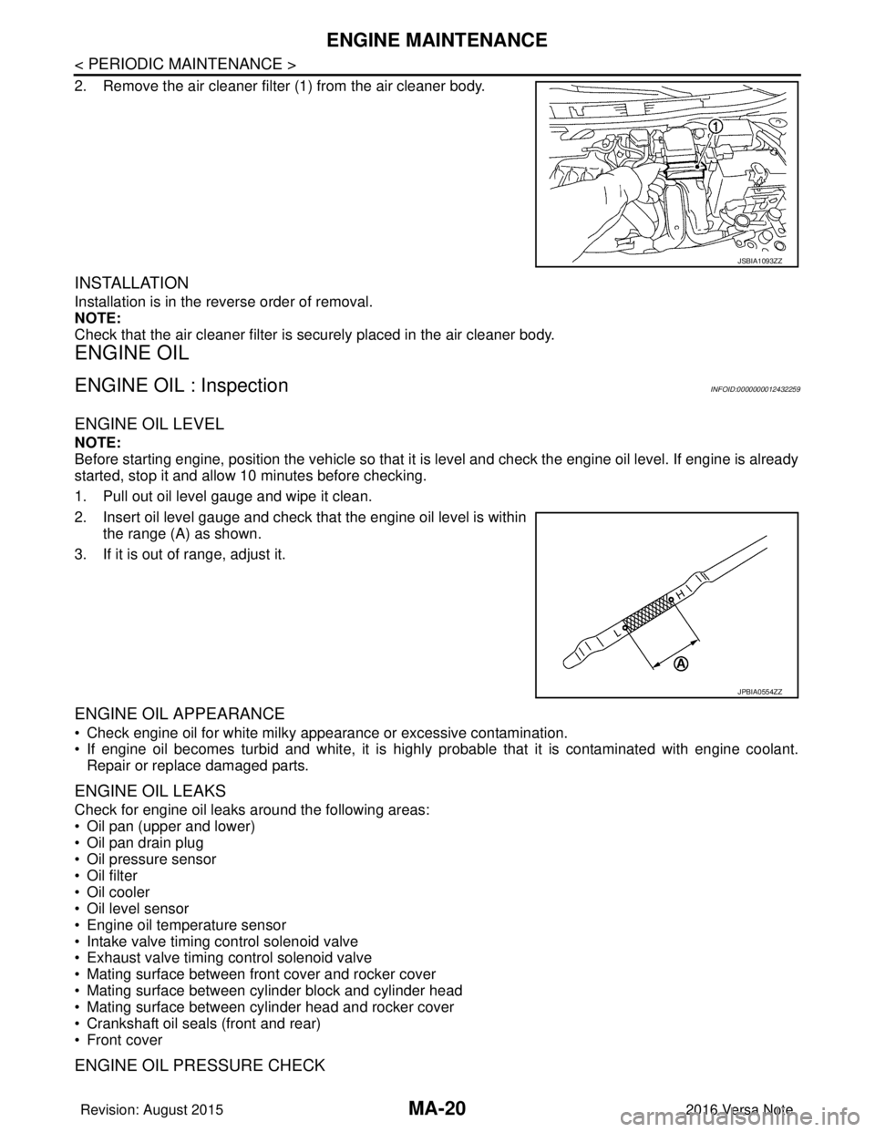
ENGINE OIL LEVEL
NOTE:
Before starting engine, position the vehicle so that it is level and check the engine oil level. If engine is already
started, stop it and allow 10 minutes before checking.
1. Pull out oil level gauge and wipe it clean.
2. Insert oil level gauge and check that the engine oil level is withinthe range (A) as shown.
3. If it is out of range, adjust it.
ENGINE OIL APPEARANCE
• Check engine oil for white milky appearance or excessive contamination.
• If engine oil becomes turbid and white, it is highl y probable that it is contaminated with engine coolant.
Repair or replace damaged parts.
ENGINE OIL LEAKS
Check for engine oil leaks around the following areas:
• Oil pan (upper and lower)
• Oil pan drain plug
• Oil pressure sensor
• Oil filter
• Oil cooler
• Oil level sensor
• Engine oil temperature sensor
• Intake valve timing control solenoid valve
• Exhaust valve timing control solenoid valve
• Mating surface between front cover and rocker cover
• Mating surface between cylinder block and cylinder head
• Mating surface between cylinder head and rocker cover
• Crankshaft oil seals (front and rear)
• Front cover
ENGINE OIL PRESSURE CHECK
JSBIA1093ZZ
JPBIA0554ZZ
Revision: August 2015 2016 Versa Note
cardiagn.com