Page 3536 of 3641

WCS
DIAGNOSIS SYSTEM (BCM) (WITH INTELLIGENT KEY SYSTEM)
WCS-21
< SYSTEM DESCRIPTION >
C
D E
F
G H
I
J
K L
M B A
O P
DIAGNOSIS SYSTEM (BCM) (WIT H INTELLIGENT KEY SYSTEM)
COMMON ITEM
COMMON ITEM : CONSULT Function (BCM - COMMON ITEM)INFOID:0000000012542986
APPLICATION ITEM
CONSULT performs the following functions via CAN communication with BCM.
SYSTEM APPLICATION
BCM can perform the following functions.
Direct Diagnostic Mode Description
ECU Identification The BCM part number is displayed.
Self Diagnostic Result The BCM self diagnostic results are displayed.
Data Monitor The BCM input/output data is displayed in real time.
Active Test The BCM activates outputs to test components.
Work support The settings for BCM functions can be changed.
Configuration • The vehicle specification can be read and saved.
• The vehicle specification can be written when replacing BCM.
CAN DIAG SUPPORT MNTR The result of transmit/receive diagnosis of CAN communication is displayed.
System Sub System Direct Diagnostic Mode
ECU Identification
Self Diagnostic Result
Data Monitor
Active Test
Work support
Configuration
CAN DIAG SUPPORT MNTR
Door lock
DOOR LOCK ×××
Rear window defogger REAR DEFOGGER ××
Warning chime BUZZER ××
Interior room lamp timer INT LAMP ×××
Exterior lamp HEAD LAMP ×××
Wiper and washer WIPER ×××
Turn signal and hazard warning lamps FLASHER ×××
Air conditioner AIR CONDITIONER ×
Intelligent Key system INTELLIGENT KEY ××××
Combination switch COMB SW ×
BCM BCM× × ×××
Immobilizer IMMU ××××
Interior room lamp battery saver BATTERY SAVER ×××
Vehicle security system THEFT ALM ××
RAP system RETAINED PWR ×
Signal buffer system SIGNAL BUFFER ×
TPMS AIR PRESSURE MONITOR ××××
Panic alarm system PANIC ALARM ×
Revision: August 2015 2016 Versa Note
cardiagn.com
Page 3537 of 3641
![NISSAN NOTE 2016 Service Repair Manual WCS-22
< SYSTEM DESCRIPTION >
DIAGNOSIS SYSTEM (BCM) (WITH INTELLIGENT KEY SYSTEM)
BUZZER
BUZZER : CONSULT Function (BCM - BUZZER)INFOID:0000000012542987
DATA MONITOR
ACTIVE TEST
Monitor Item [Unit] D NISSAN NOTE 2016 Service Repair Manual WCS-22
< SYSTEM DESCRIPTION >
DIAGNOSIS SYSTEM (BCM) (WITH INTELLIGENT KEY SYSTEM)
BUZZER
BUZZER : CONSULT Function (BCM - BUZZER)INFOID:0000000012542987
DATA MONITOR
ACTIVE TEST
Monitor Item [Unit] D](/manual-img/5/57363/w960_57363-3536.png)
WCS-22
< SYSTEM DESCRIPTION >
DIAGNOSIS SYSTEM (BCM) (WITH INTELLIGENT KEY SYSTEM)
BUZZER
BUZZER : CONSULT Function (BCM - BUZZER)INFOID:0000000012542987
DATA MONITOR
ACTIVE TEST
Monitor Item [Unit] Description
PUSH SW [On/Off] Indicates condition of push-button ignition switch.
UNLK SEN -DR [On/Off] Indicates condition of door unlock sensor.
VEH SPEED 1 [km/h] Indicates vehicle speed signal received from ABS on CAN communication line.
TAIL LAMP SW [On/Off] Indicates condition of combination switch.
FR FOG SW [On/Off] Indicates condition of front fog lamp switch.
DOOR SW-DR [On/Off] Indicates condition of front door switch LH.
CDL LOCK SW [On/Off] Indicates condition of lock signal from door lock and unlock switch.
Test Item Description
ID REGIST WARNING This test is able to check TPMS transmitter ID regist warning chime operation [On/Off].
SEAT BELT WARN TEST This test is able to check seat belt warning chime operation [On/Off].
LIGHT WARN ALM This test is able to check light warning chime operation [On/Off].
Revision: August 2015 2016 Versa Note
cardiagn.com
Page 3538 of 3641

WCS
DIAGNOSIS SYSTEM (BCM) (WITHOUT INTELLIGENT KEY SYSTEM)WCS-23
< SYSTEM DESCRIPTION >
C
DE
F
G H
I
J
K L
M B A
O P
DIAGNOSIS SYSTEM (BCM) (WITHO UT INTELLIGENT KEY SYSTEM)
COMMON ITEM
COMMON ITEM : CONSULT Function (BCM - COMMON ITEM)INFOID:0000000012542988
APPLICATION ITEM
CONSULT performs the following functions via CAN communication with BCM.
SYSTEM APPLICATION
BCM can perform the following functions.
Direct Diagnostic Mode Description
ECU Identification The BCM part number is displayed.
Self Diagnostic Result The BCM self diagnostic results are displayed.
Data Monitor The BCM input/output data is displayed in real time.
Active Test The BCM activates outputs to test components.
Work support The settings for BCM functions can be changed.
Configuration • The vehicle specification can be read and saved.
• The vehicle specification can be written when replacing BCM.
CAN DIAG SUPPORT MNTR The result of transmit/receive diagnosis of CAN communication is displayed.
System Sub System Direct Diagnostic Mode
ECU Identification
Self Diagnostic Result
Data Monitor
Active Test
Work support
Configuration
CAN DIAG SUPPORT MNTR
Door lock
DOOR LOCK ×××
Rear window defogger REAR DEFOGGER ××
Warning chime BUZZER ××
Interior room lamp timer INT LAMP ×××
Remote keyless entry system MULTI REMOTE ENT ×××
Exterior lamp HEAD LAMP ×××
Wiper and washer WIPER ×××
Turn signal and hazard warning lamps FLASHER ××
Air conditioner AIR CONDITIONER ×
Combination switch COMB SW ×
BCM BCM× × ×××
Immobilizer IMMU ×××
Interior room lamp battery saver BATTERY SAVER ×××
Vehicle security system THEFT ALM ××
RAP system RETAINED PWR ××
Signal buffer system SIGNAL BUFFER ×
TPMS AIR PRESSURE MONITOR ××××
Panic alarm system PANIC ALARM ×
Revision: August 2015 2016 Versa Note
cardiagn.com
Page 3539 of 3641

WCS-24
< SYSTEM DESCRIPTION >
DIAGNOSIS SYSTEM (BCM) (WITHOUT INTELLIGENT KEY SYSTEM)
BUZZER
BUZZER : CONSULT Function (BCM - BUZZER)INFOID:0000000012542989
DATA MONITOR
ACTIVE TEST
Monitor Item [Unit] Description
IGN ON SW [On/Off] Indicates condition of ignition switch ON position.
KEY ON SW [On/Off] Indicates condition of key switch.
DOOR SW-DR [On/Off] Indicates condition of front door switch LH.
REVERSE SW CAN [On/Off] Indicates reverse switch sign al received from TCM on CAN communication line.
TAIL LAMP SW [On/Off] Indicates condition of combination switch.
FR FOG SW [On/Off] Indicates condition of front fog lamp switch.
VEHICLE SPEED [km/h/mph] Indicates vehicle speed signal received from combination meter on CAN communication line.
Test Item Description
IGN KEY WARN ALM This test is able to check key warning chime operation [On/Off].
SEAT BELT WARN TEST This test is able to check seat belt warning chime operation [On/Off].
LIGHT WARN ALM This test is able to check light warning chime operation [On/Off].
Revision: August 2015 2016 Versa Note
cardiagn.com
Page 3540 of 3641
WCS
BCM, COMBINATION METERWCS-25
< ECU DIAGNOSIS INFORMATION >
C
DE
F
G H
I
J
K L
M B A
O P
ECU DIAGNOSIS INFORMATION
BCM, COMBINATION METER
List of ECU ReferenceINFOID:0000000012432683
ECU Reference
BCM
(with Intelligent Key system) BCS-30, "
Reference Value"
BCS-48, "Fail-safe"
BCS-49, "DTCInspectionPriorityChart"
BCS-50, "DTCIndex"
BCM
(without Intelligent Key system)BCS-101, "
Reference Value"
BCS-115, "Fail-safe"
BCS-115, "DTCInspectionPriorityChart"
BCS-115, "DTCIndex"
COMBINATION METER
(TYPE A)
MWI-21, "
Reference Value"
MWI-23, "Fail-safe"
MWI-24, "DTC Index"
COMBINATION METER
(TYPE B)MWI-74, "
Reference Value"
MWI-77, "Fail-safe"
MWI-77, "DTC Index"
Revision: August 2015
2016 Versa Note
cardiagn.com
Page 3550 of 3641

WCS
POWER SUPPLY AND GROUND CIRCUITWCS-35
< DTC/CIRCUIT DIAGNOSIS >
C
DE
F
G H
I
J
K L
M B A
O P
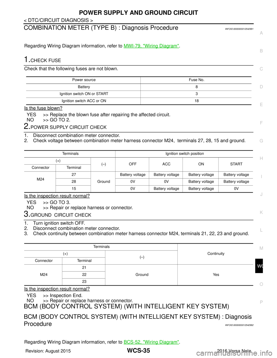
COMBINATION METER (TYPE B) : Diagnosis ProcedureINFOID:0000000012542991
Regarding Wiring Diagram information, refer to MWI-79, "Wiring Diagram".
1.CHECK FUSE
Check that the following fuses are not blown.
Is the fuse blown?
YES >> Replace the blown fuse after repairing the affected circuit.
NO >> GO TO 2.
2.POWER SUPPLY CIRCUIT CHECK
1. Disconnect combination meter connector.
2. Check voltage between combination meter harness connector M24, terminals 27, 28, 15 and ground.
Is the inspection result normal?
YES >> GO TO 3.
NO >> Repair or replace harness or connector.
3.GROUND CIRCUIT CHECK
1. Turn ignition switch OFF.
2. Disconnect combination meter connector.
3. Check continuity between combination meter harness connector M24, terminals 21, 22, 23 and ground.
Is the inspection result normal?
YES >> Inspection End.
NO >> Repair or replace harness or connector.
BCM (BODY CONTROL SYSTEM) (W ITH INTELLIGENT KEY SYSTEM)
BCM (BODY CONTROL SYSTEM) (WITH IN TELLIGENT KEY SYSTEM) : Diagnosis
Procedure
INFOID:0000000012542992
Regarding Wiring Diagram information, refer to BCS-52, "Wiring Diagram".
Power source Fuse No.
Battery 8
Ignition switch ON or START 3
Ignition switch ACC or ON 18
TerminalsIgnition switch position
(+) (–)OFF ACC ONSTART
Connector Terminal
M24 27
GroundBattery voltage Battery voltage Battery voltage Battery voltage
28 0V0VBattery voltage Battery voltage
15 0V Battery voltage Battery voltage 0V
Te r m i n a l s
Continuity
(+)
(–)
Connector Terminal
M24 21
Ground Yes
22
23
Revision: August 2015 2016 Versa Note
cardiagn.com
Page 3551 of 3641

WCS-36
< DTC/CIRCUIT DIAGNOSIS >
POWER SUPPLY AND GROUND CIRCUIT
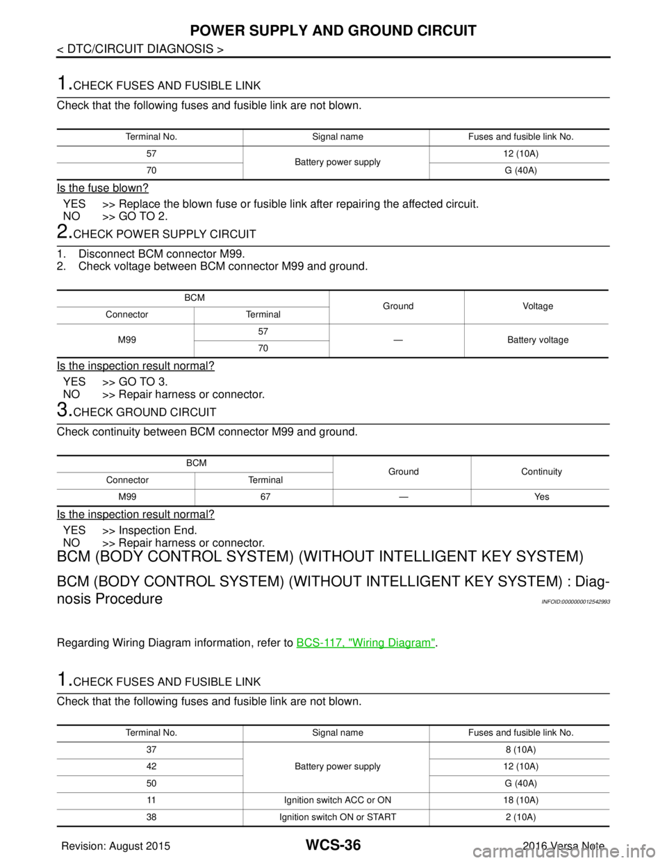
1.CHECK FUSES AND FUSIBLE LINK
Check that the following fuses and fusible link are not blown.
Is the fuse blown?
YES >> Replace the blown fuse or fusible link after repairing the affected circuit.
NO >> GO TO 2.
2.CHECK POWER SUPPLY CIRCUIT
1. Disconnect BCM connector M99.
2. Check voltage between BCM connector M99 and ground.
Is the inspection result normal?
YES >> GO TO 3.
NO >> Repair harness or connector.
3.CHECK GROUND CIRCUIT
Check continuity between BCM connector M99 and ground.
Is the inspection result normal?
YES >> Inspection End.
NO >> Repair harness or connector.
BCM (BODY CONTROL SYSTEM) (WIT HOUT INTELLIGENT KEY SYSTEM)
BCM (BODY CONTROL SYSTEM) (WITHOUT INTELLIGENT KEY SYSTEM) : Diag-
nosis Procedure
INFOID:0000000012542993
Regarding Wiring Diagram information, refer to BCS-117, "Wiring Diagram".
1.CHECK FUSES AND FUSIBLE LINK
Check that the following fuses and fusible link are not blown.
Terminal No. Signal nameFuses and fusible link No.
57 Battery power supply 12 (10A)
70 G (40A)
BCM
Ground Voltage
Connector Terminal
M99 57
— Battery voltage
70
BCM GroundContinuity
Connector Terminal
M99 67—Yes
Terminal No. Signal nameFuses and fusible link No.
37 Battery power supply 8 (10A)
42 12 (10A)
50 G (40A)
11 Ignition switch ACC or ON 18 (10A)
38 Ignition switch ON or START 2 (10A)
Revision: August 2015 2016 Versa Note
cardiagn.com
Page 3553 of 3641

WCS-38
< DTC/CIRCUIT DIAGNOSIS >
METER BUZZER CIRCUIT
METER BUZZER CIRCUIT
Component Function CheckINFOID:0000000012432690
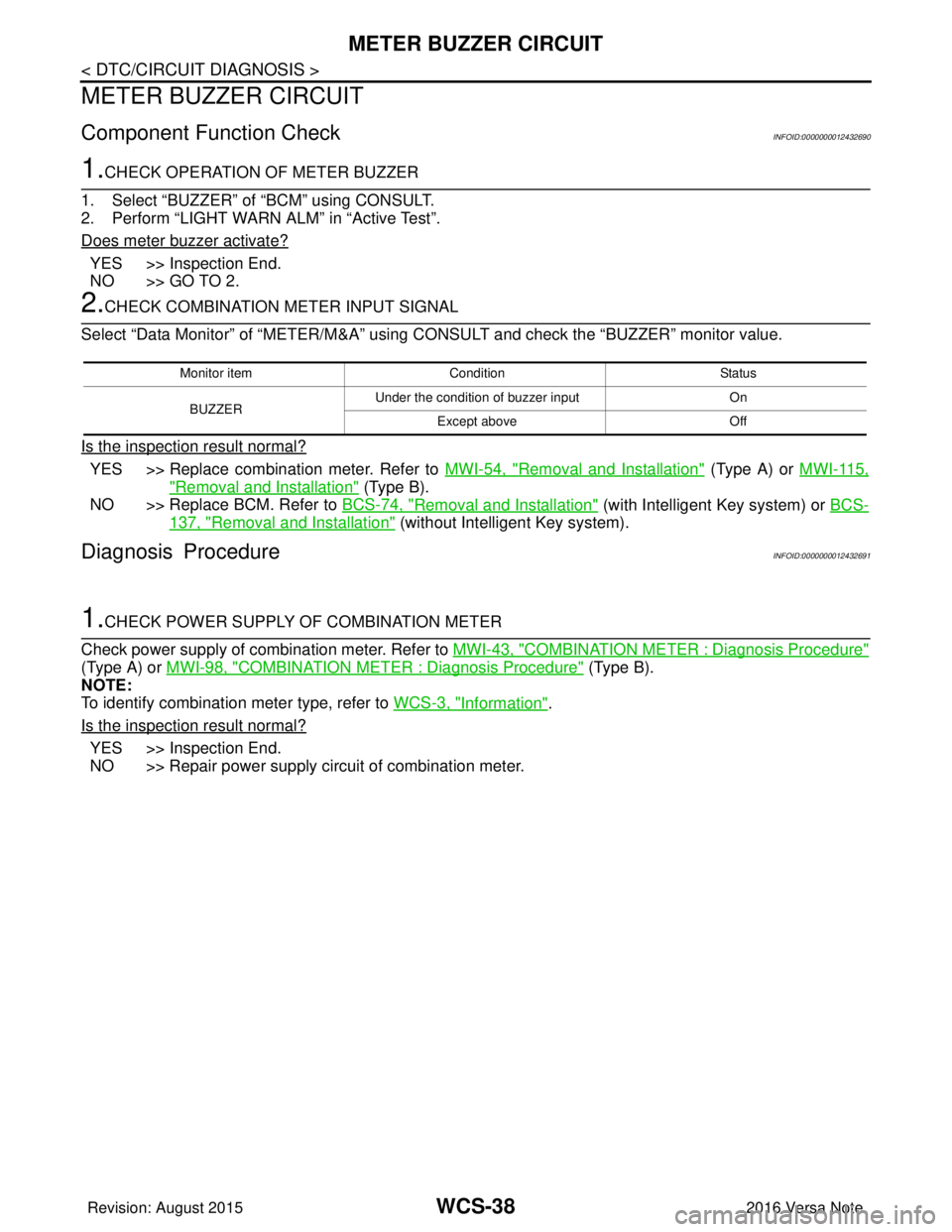
1.CHECK OPERATION OF METER BUZZER
1. Select “BUZZER” of “BCM” using CONSULT.
2. Perform “LIGHT WARN ALM” in “Active Test”.
Does meter buzzer activate?
YES >> Inspection End.
NO >> GO TO 2.
2.CHECK COMBINATION METER INPUT SIGNAL
Select “Data Monitor” of “METER/M&A” using CONSULT and check the “BUZZER” monitor value.
Is the inspection result normal?
YES >> Replace combination meter. Refer to MWI-54, "Removal and Installation" (Type A) or MWI-115,
"Removal and Installation" (Type B).
NO >> Replace BCM. Refer to BCS-74, "
Removal and Installation" (with Intelligent Key system) or BCS-
137, "Removal and Installation" (without Intelligent Key system).
Diagnosis ProcedureINFOID:0000000012432691
1.CHECK POWER SUPPLY OF COMBINATION METER
Check power supply of combination meter. Refer to MWI-43, "
COMBINATION METER : Diagnosis Procedure"
(Type A) or MWI-98, "COMBINATION METER : Diagnosis Procedure" (Type B).
NOTE:
To identify combination meter type, refer to WCS-3, "
Information".
Is the inspection result normal?
YES >> Inspection End.
NO >> Repair power supply circuit of combination meter.
Monitor item Condition Status
BUZZER Under the condition of buzzer input
On
Except above Off
Revision: August 2015 2016 Versa Note
cardiagn.com