Page 3156 of 3641
STR-4
< SYSTEM DESCRIPTION >
COMPONENT PARTS
SYSTEM DESCRIPTION
COMPONENT PARTS
STARTING SYSTEM (WITHOUT INTELLIGENT KEY)
STARTING SYSTEM (WITHOUT INTELLIGENT KEY) : Component Parts Location
INFOID:0000000012432060
:Vehicle front
A. Enginr room left side. B. View with CVT removed. C. View with engine removed.
D. Clutch pedal area.
ALBIA1229ZZ
Revision: August 2015 2016 Versa Note
cardiagn.com
Page 3157 of 3641
COMPONENT PARTSSTR-5
< SYSTEM DESCRIPTION >
C
DE
F
G H
I
J
K L
M A
STR
NP
O
STARTING SYSTEM (WITHOUT INTELL
IGENT KEY) : Component Description
INFOID:0000000012432061
STARTING SYSTEM (WITH INTELLIGENT KEY)
No.Component part Description
1. IPDM E/R CPU inside IPDM E/R operates the starter control relay when
the ignition switch is in the start position.
2. Transmission range switch (CVT Models) Supplies power to the starter co
ntrol relay (inside IPDM E/R)
when the selector lever is shifted into the P or N position.
3. Starter motor The starter motor plunger closes and the motor is supplied
with battery power, which in turn cranks the engine, when the
S terminal is supplied with electric power.
4. Clutch interlock switch (M/T Models) Clutch interlock switch supplies power to the coil side of the
starter control relay when the clutch pedal is depressed to
crank the engine.
Revision: August 2015
2016 Versa Note
cardiagn.com
Page 3158 of 3641
STR-6
< SYSTEM DESCRIPTION >
COMPONENT PARTS
STARTING SYSTEM (WITH INTELLIGEN T KEY) : Component Parts Location
INFOID:0000000012432062
STARTING SYSTEM (WITH INTELLIGENT KEY) : Component Description
INFOID:0000000012432063
Vehicle front
A. Engine room left side. B. View with CVT removed. C. View with engine removed.
D. Clutch pedal area. E. Left side of instrument panel.
ALBIA1230ZZ
No. Component part Description
1. IPDM E/R CPU inside IPDM E/R operates the starter control relay when the ig-
nition switch is in the start position.
2. Transmission range switch Supplies power to the starter relay
and starter control relay (inside
IPDM E/R) when the selector lever is shifted into the P or N position.
Revision: August 2015 2016 Versa Note
cardiagn.com
Page 3160 of 3641
STR-8
< SYSTEM DESCRIPTION >
SYSTEM
SYSTEM
STARTING SYSTEM (WITHOUT INTELLIGENT KEY)
STARTING SYSTEM (WITHOUT INTELLIGENT KEY) : System DiagramINFOID:0000000012432064
STARTING SYSTEM (WITHOUT INTELLI GENT KEY) : System Description
INFOID:0000000012432065
The starter motor plunger closes and provides a closed circuit between the battery and the starter motor. The
starter motor is grounded to the cylinder block. With power and ground supplied, the starter motor operates.
STARTING SYSTEM (WITH INTELLIGENT KEY)
ALBIA1161GB
Revision: August 2015 2016 Versa Note
cardiagn.com
Page 3161 of 3641
SYSTEMSTR-9
< SYSTEM DESCRIPTION >
C
DE
F
G H
I
J
K L
M A
STR
NP
O
STARTING SYSTEM (WITH INTELL
IGENT KEY) : System DiagramINFOID:0000000012432066
STARTING SYSTEM (WITH INTELLIG ENT KEY) : System DescriptionINFOID:0000000012432067
• When the selector lever is in the P or N position, power is supplied to starter relay and starter control relay by
the transmission range switch. The BCM and IPDM E/R (C PU) will detect the selector lever position by the
input signal.
• When the starter operating condition is met, the IPDM E/R will turn the starter control relay ON by starter
control relay control signal.
• When engine cranking condition is met, the BCM turns ON the starter relay by starter control relay signal.
• Then battery power is supplied to starter motor (“S” terminal) through the starter control relay and starter
relay.
ALBIA1231GB
Revision: August 2015 2016 Versa Note
cardiagn.com
Page 3162 of 3641
STR-10
< WIRING DIAGRAM >
STARTING SYSTEM
WIRING DIAGRAM
STARTING SYSTEM
Wiring Diagram - With Intelligent Key SystemINFOID:0000000012432068
ABBWA1633GB
Revision: August 2015 2016 Versa Note
cardiagn.com
Page 3168 of 3641
STR-16
< WIRING DIAGRAM >
STARTING SYSTEM
Wiring Diagram - Without Intelligent Key System
INFOID:0000000012432069
ABBWA1634GB
Revision: August 2015 2016 Versa Note
cardiagn.com
Page 3179 of 3641

B TERMINAL CIRCUITSTR-27
< DTC/CIRCUIT DIAGNOSIS >
C
DE
F
G H
I
J
K L
M A
STR
NP
O
DTC/CIRCUIT DIAGNOSIS
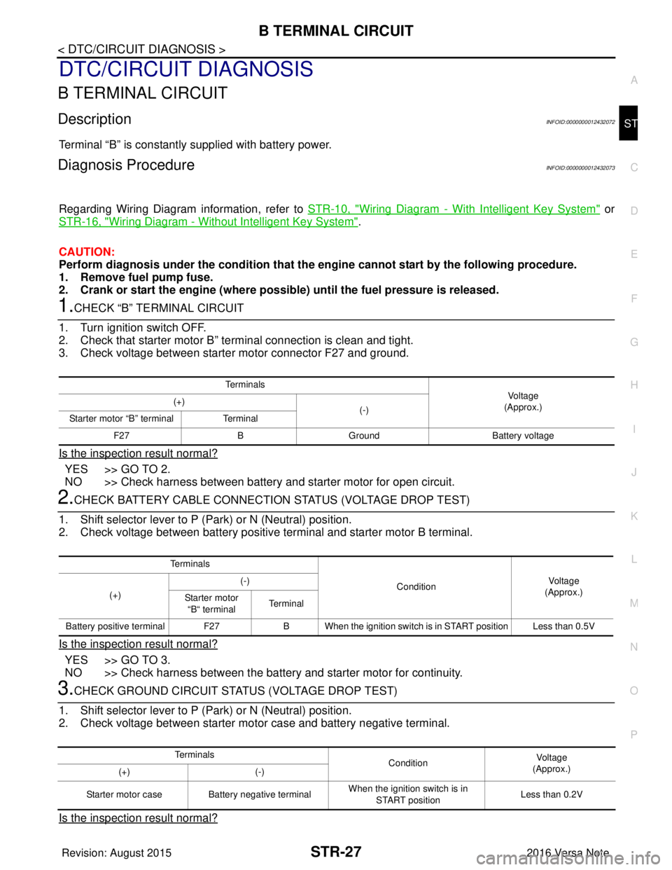
B TERMINAL CIRCUIT
DescriptionINFOID:0000000012432072
Terminal “B” is constantly supplied with battery power.
Diagnosis ProcedureINFOID:0000000012432073
Regarding Wiring Diagram information, refer to
STR-10, "Wiring Diagram - With Intelligent Key System" or
STR-16, "
Wiring Diagram - Without Intelligent Key System".
CAUTION:
Perform diagnosis under the cond ition that the engine cannot start by the following procedure.
1. Remove fuel pump fuse.
2. Crank or start the engine (where possi ble) until the fuel pressure is released.
1.CHECK “B” TERMINAL CIRCUIT
1. Turn ignition switch OFF.
2. Check that starter motor B” terminal connection is clean and tight.
3. Check voltage between starter motor connector F27 and ground.
Is the inspection result normal?
YES >> GO TO 2.
NO >> Check harness between battery and starter motor for open circuit.
2.CHECK BATTERY CABLE CONNECTION STATUS (VOLTAGE DROP TEST)
1. Shift selector lever to P (P ark) or N (Neutral) position.
2. Check voltage between battery positive terminal and starter motor B terminal.
Is the inspection result normal?
YES >> GO TO 3.
NO >> Check harness between the battery and starter motor for continuity.
3.CHECK GROUND CIRCUIT STATUS (VOLTAGE DROP TEST)
1. Shift selector lever to P (P ark) or N (Neutral) position.
2. Check voltage between starter motor case and battery negative terminal.
Is the inspection result normal?
Te r m i n a l s
Voltage
(Approx.)
(+)
(-)
Starter motor “B” terminal Terminal
F27 BGround Battery voltage
Te r m i n a l s
ConditionVoltage
(Approx.)
(+) (-)
Starter motor “B“ terminal Terminal
Battery positive terminal F27 B When the ignition switch is in START position Less than 0.5V
Te r m i n a l s
ConditionVoltage
(Approx.)
(+) (-)
Starter motor case Battery negative terminal When the ignition switch is in
START position Less than 0.2V
Revision: August 2015
2016 Versa Note
cardiagn.com