2016 NISSAN NOTE key
[x] Cancel search: keyPage 3516 of 3641

WCS
WCS-1
DRIVER INFORMATION & MULTIMEDIA
C
DE
F
G H
I
J
K L
M B
SECTION WCS
A
O P
CONTENTS
WARNING CHIME SYSTEM
HOW TO USE THIS MANU AL ......................3
APPLICATION NOTICE ................................. .....3
Information .......................................................... ......3
PRECAUTION ...............................................4
PRECAUTIONS .............................................. .....4
Precaution for Supplemental Restraint System
(SRS) "AIR BAG" and "SEAT BELT PRE-TEN-
SIONER" ............................................................. ......
4
SYSTEM DESCRIPTION ..............................5
COMPONENT PARTS ................................... .....5
Component Parts Location .................................. ......5
Combination Meter ....................................................5
SYSTEM ..............................................................7
WARNING CHIME SYSTEM .......................................7
WARNING CHIME SYSTEM : System Description
......
7
WARNING CHIME SYSTEM : Fail-safe ....................8
LIGHT REMINDER WARNING CHIME ................. ......8
LIGHT REMINDER WARNING CHIME : Light Re-
minder Warning .........................................................
8
PARKING BRAKE RELEASE WARNING CHIME ......9
PARKING BRAKE RELEASE WARNING CHIME
: Parking Brake Release Warning Chime ............ ......
9
SEAT BELT REMINDER WARNING CHIME ........ ....10
SEAT BELT REMINDER WARNING CHIME :
Seat belt Warning ....................................................
10
KEY WARNING CHIME (WITHOUT INTELLIGENT
KEY) ....................................................................... ....
11
KEY WARNING CHIME (WITHOUT INTELLI-
GENT KEY) : Key Warning Chime ..........................
11
DIAGNOSIS SYSTEM (COMBINATION
METER) .............................................................
13
TYPE A ............................................ ...........................13
TYPE A : On Board Diagnosis Function .............. ....13
TYPE A : CONSULT Function (METER/M&A) ........14
TYPE B ............................................ ...........................16
TYPE B : On Board Diagnosis Function .............. ....16
TYPE B : CONSULT Function (METER/M&A) ........18
DIAGNOSIS SYSTEM (BCM) (WITH INTELLI-
GENT KEY SYSTEM) .......................................
21
COMMON ITEM ..................................................... ....21
COMMON ITEM : CONSULT Function (BCM -
COMMON ITEM) .....................................................
21
BUZZER ................................................................. ....22
BUZZER : CONSULT Function (BCM - BUZZER) ....22
DIAGNOSIS SYSTEM (BCM) (WITHOUT IN-
TELLIGENT KEY SYSTEM) .............................
23
COMMON ITEM ..................................................... ....23
COMMON ITEM : CONSULT Function (BCM -
COMMON ITEM) .....................................................
23
BUZZER ................................................................. ....24
BUZZER : CONSULT Function (BCM - BUZZER) ....24
ECU DIAGNOSIS INFORMATION ..............25
BCM, COMBINATION METER .........................25
List of ECU Reference ......................................... ....25
WIRING DIAGRAM ......................................26
WARNING CHIME SYSTEM .............................26
Wiring Diagram .................................................... ....26
BASIC INSPECTION ...................................32
DIAGNOSIS AND REPAIR WORK FLOW .......32
Revision: August 2015 2016 Versa Note
cardiagn.com
Page 3517 of 3641

WCS-2
Work Flow ...............................................................32
DTC/CIRCUIT DIAGNOSIS ...................... ...34
POWER SUPPLY AND GROUND CIRCUIT .. ...34
COMBINATION METER (TYPE A) ........................ ...34
COMBINATION METER (TYPE A) : Diagnosis
Procedure ............................................................ ...
34
COMBINATION METER (TYPE B) ........................ ...34
COMBINATION METER (TYPE B) : Diagnosis
Procedure ............................................................ ...
35
BCM (BODY CONTROL SYSTEM) (WITH INTEL-
LIGENT KEY SYSTEM) ..... .......................................
35
BCM (BODY CONTROL S YSTEM) (WITH INTEL-
LIGENT KEY SYSTEM) : Dia gnosis Procedure .....
35
BCM (BODY CONTROL SYST EM) (WITHOUT IN-
TELLIGENT KEY SYSTEM) . ....................................
36
BCM (BODY CONTROL SYSTEM) (WITHOUT
INTELLIGENT KEY SYSTEM) : Diagnosis Proce-
dure ..................................................................... ...
36
METER BUZZER CIRCUIT ................................38
Component Function Check ................................ ...38
Diagnosis Procedure .............................................38
SEAT BELT BUCKLE SWITCH SIGNAL CIR-
CUIT ...................................................................
39
TYPE A ................................................................... ...39
TYPE A : Description ..............................................39
TYPE A : Component Func tion Check ..................39
TYPE A : Diagnosis Procedu re ..............................39
TYPE A : Component Inspec tion ............................40
TYPE B ............... .................................................... ...40
TYPE B : Description ..............................................40
TYPE B : Component Func tion Check ..................40
TYPE B : Diagnosis Procedu re ..............................40
TYPE B : Component Inspec tion ............................41
PARKING BRAKE SWITCH SIGNAL CIR-
CUIT ................................................................ ...
42
TYPE A ............................................ ..........................42
TYPE A : Component Functi on Check ....................42
TYPE A : Diagnosis Procedur e ...............................42
TYPE A : Component Inspec tion ............................43
TYPE B ............ ................................ ..........................43
TYPE B : Component Functi on Check ....................43
TYPE B : Diagnosis Procedur e ...............................43
TYPE B : Component Inspec tion ............................44
KEY SWITCH SIGNAL CIRCUIT (WITHOUT
INTELLIGENT KEY) ....................................... ...
45
Description ........................................................... ...45
Component Function Check ..................................45
Diagnosis Procedure ..............................................45
Component Inspection ............................................46
SYMPTOM DIAGNOSIS ............................47
THE PARKING BRAKE RELEASE WARNING
CONTINUES SOUNDING, OR DOES NOT
SOUND ........................................................... ...
47
Description ........................................................... ...47
Diagnosis Procedure ...............................................47
THE SEAT BELT REMINDER WARNING
CONTINUES SOUNDING, OR DOES NOT
SOUND ..............................................................
48
Description ........................................................... ...48
Diagnosis Procedure ...............................................48
THE LIGHT REMINDER WARNING DOES
NOT SOUND ......................................................
49
Description ........................................................... ...49
Diagnosis Procedure ...............................................49
THE KEY WARNING DOES NOT SOUND
(WITHOUT INTELLIGENT KEY) .......................
50
Description ..............................................................50
Diagnosis Procedure ...............................................50
Revision: August 2015 2016 Versa Note
cardiagn.com
Page 3520 of 3641
WCS
COMPONENT PARTSWCS-5
< SYSTEM DESCRIPTION >
C
DE
F
G H
I
J
K L
M B A
O P
SYSTEM DESCRIPTION
COMPONENT PARTS
Component Parts LocationINFOID:0000000012432667
Combination MeterINFOID:0000000012432668
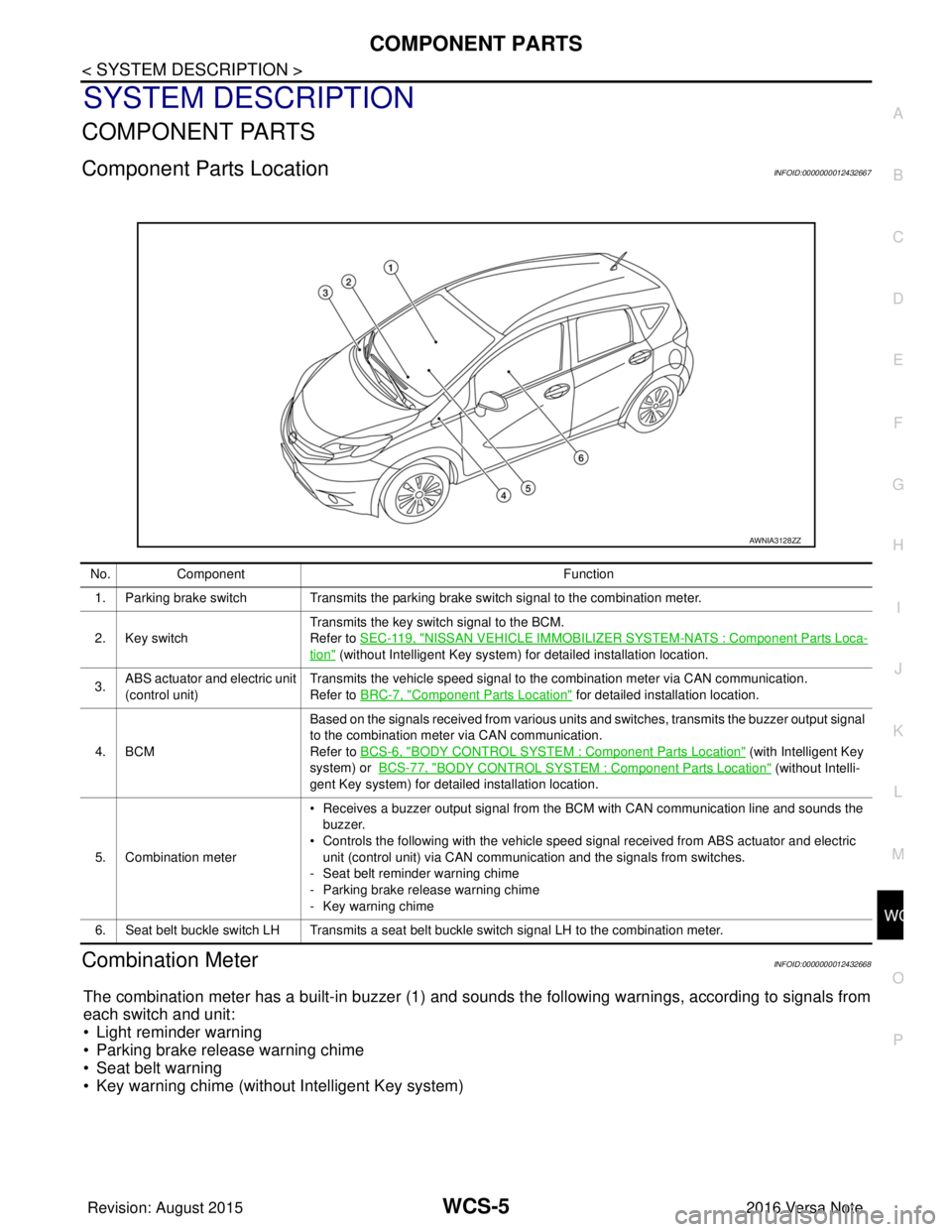
The combination meter has a built-in buzzer (1) and sounds the following warnings, according to signals from
each switch and unit:
• Light reminder warning
• Parking brake release warning chime
• Seat belt warning
• Key warning chime (without Intelligent Key system)
AWNIA3128ZZ
No. Component Function
1. Parking brake switch Transmits the parking brake switch signal to the combination meter.
2. Key switch Transmits the key switch signal to the BCM.
Refer to
SEC-119, "
NISSAN VEHICLE IMMOBILIZER SYSTEM -NATS : Component Parts Loca-
tion" (without Intelligent Key system) for detailed installation location.
3. ABS actuator and electric unit
(control unit) Transmits the vehicle speed signal to the combination meter via CAN communication.
Refer to BRC-7, "
Component Parts Location" for detailed installation location.
4. BCM Based on the signals received from various units and switches, transmits the buzzer output signal
to the combination meter via CAN communication.
Refer to BCS-6, "
BODY CONTROL SYSTEM : Co
mponent Parts Location" (with Intelligent Key
system) or BCS-77, "
BODY CONTROL SYSTEM : Component Parts Location" (without Intelli-
gent Key system) for detailed installation location.
5. Combination meter • Receives a buzzer output signal from the BCM with CAN communication line and sounds the
buzzer.
• Controls the following with the vehicle speed signal received from ABS actuator and electric
unit (control unit) via CAN communication and the signals from switches.
- Seat belt reminder warning chime
- Parking brake release warning chime
- Key warning chime
6. Seat belt buckle switch LH Transmits a seat belt buckle switch signal LH to the combination meter.
Revision: August 2015 2016 Versa Note
cardiagn.com
Page 3522 of 3641
WCS
SYSTEMWCS-7
< SYSTEM DESCRIPTION >
C
DE
F
G H
I
J
K L
M B A
O P
SYSTEM
WARNING CHIME SYSTEM
WARNING CHIME SYSTEM : System DescriptionINFOID:0000000012432669
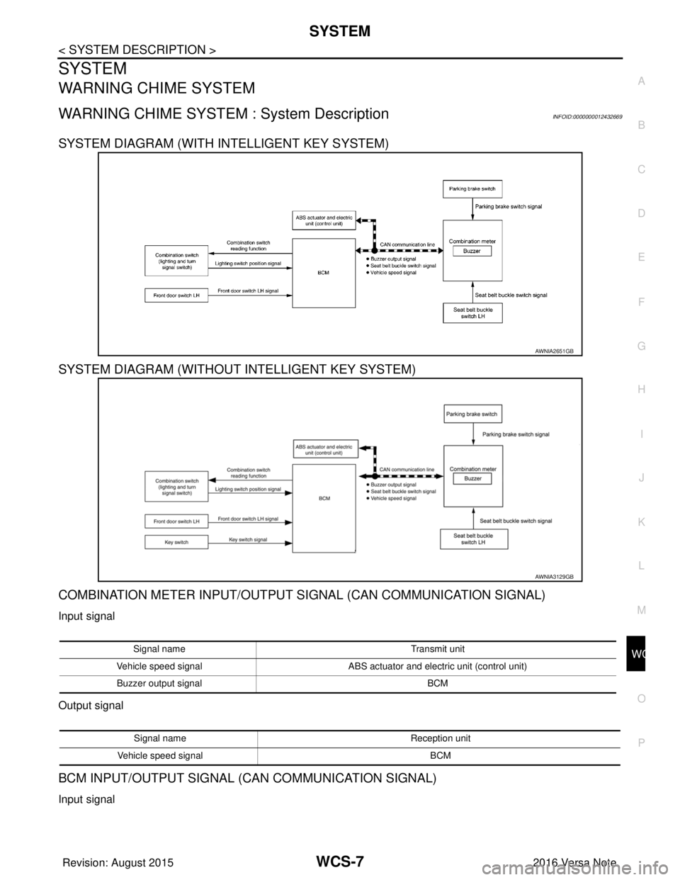
SYSTEM DIAGRAM (WITH INTELLIGENT KEY SYSTEM)
SYSTEM DIAGRAM (WITHOUT INTELLIGENT KEY SYSTEM)
COMBINATION METER INPUT/OUTPUT SIGNAL (CAN COMMUNICATION SIGNAL)
Input signal
Output signal
BCM INPUT/OUTPUT SIGNAL (CAN COMMUNICATION SIGNAL)
Input signal
AWNIA2651GB
AWNIA3129GB
Signal name Transmit unit
Vehicle speed signal ABS actuator and electric unit (control unit)
Buzzer output signal BCM
Signal nameReception unit
Vehicle speed signal BCM
Revision: August 2015 2016 Versa Note
cardiagn.com
Page 3523 of 3641
WCS-8
< SYSTEM DESCRIPTION >
SYSTEM
Output signal
DESCRIPTION
Combination Meter
The combination meter sounds the alarm buzzer installed in the combination meter when receiving the buzzer
output signal transmitted from each unit.
BCM
BCM receives signals from various units and transmits a buzzer output signal to the combination meter via
CAN communication if it judges that the warning buzzer should be activated.
WARNING CHIME FUNCTION LIST
WARNING CHIME SYSTEM : Fail-safeINFOID:0000000012432670
The combination meter activates the fail-safe contro l if CAN communication with each unit is malfunctioning.
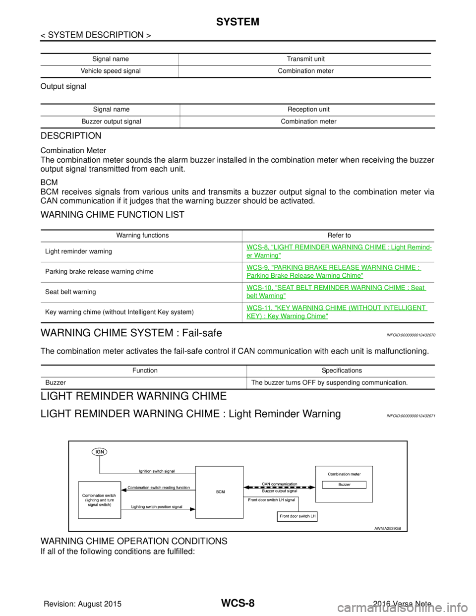
LIGHT REMINDER WARNING CHIME
LIGHT REMINDER WARNING CHIME : Light Reminder WarningINFOID:0000000012432671
WARNING CHIME OPERATION CONDITIONS
If all of the following conditions are fulfilled:
Signal name Transmit unit
Vehicle speed signal Combination meter
Signal nameReception unit
Buzzer output signal Combination meter
Warning functions Refer to
Light reminder warning WCS-8, "
LIGHT REMINDER WARNING CHIME : Light Remind-
er Warning"
Parking brake release warning chimeWCS-9, "PARKING BRAKE RELEASE WARNING CHIME :
Parking Brake Release Warning Chime"
Seat belt warningWCS-10, "SEAT BELT REMINDER WARNING CHIME : Seat
belt Warning"
Key warning chime (without Intelligent Key system)
WCS-11, "KEY WARNING CHIME (WITHOUT INTELLIGENT
KEY) : Key Warning Chime"
Function
Specifications
Buzzer The buzzer turns OFF by suspending communication.
AWNIA2539GB
Revision: August 2015 2016 Versa Note
cardiagn.com
Page 3526 of 3641
WCS
SYSTEMWCS-11
< SYSTEM DESCRIPTION >
C
DE
F
G H
I
J
K L
M B A
O P
1. BCM requires warning chime output to combination meter when it judges seat belt warning chime is nec- essary from signals below.
2. Combination meter sounds integrated buzzer, followi ng the warning chime output requirement (below sig-
nal) from BCM.
KEY WARNING CHIME (WITHOUT INTELLIGENT KEY)
KEY WARNING CHIME (WITHOUT INTELLIGENT KEY) : Key Warning Chime
INFOID:0000000012432674
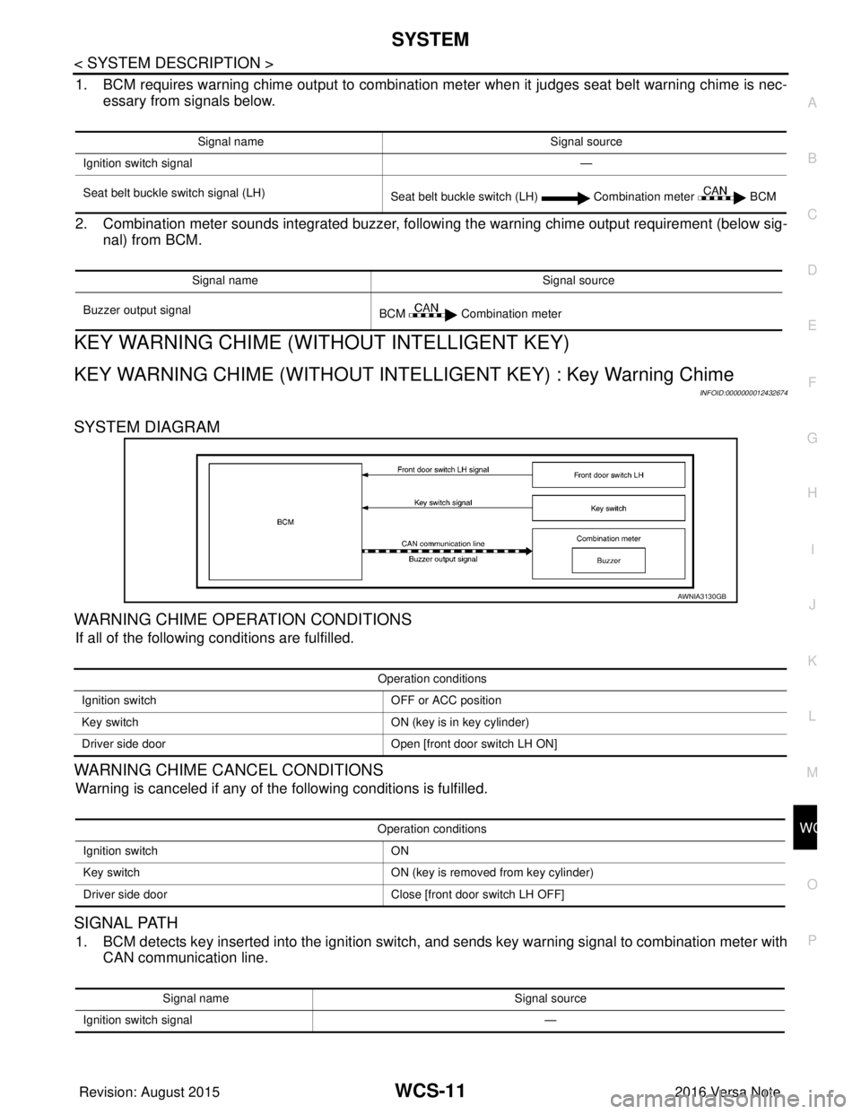
SYSTEM DIAGRAM
WARNING CHIME OPERATION CONDITIONS
If all of the following conditions are fulfilled.
WARNING CHIME CANCEL CONDITIONS
Warning is canceled if any of the following conditions is fulfilled.
SIGNAL PATH
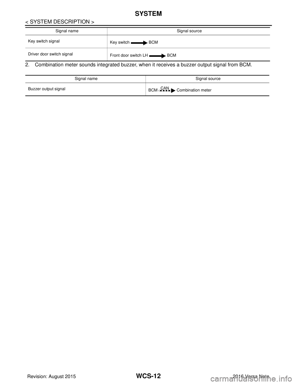
1. BCM detects key inserted into the ignition switch, and sends key warning signal to combination meter with CAN communication line.
Signal name Signal source
Ignition switch signal —
Seat belt buckle switch signal (LH) Seat belt buckle switch (LH) Combination meter BCM
Signal name Signal source
Buzzer output signal BCM Combination meter
AWNIA3130GB
Operation conditions
Ignition switch OFF or ACC position
Key switch ON (key is in key cylinder)
Driver side door Open [front door switch LH ON]
Operation conditions
Ignition switch ON
Key switch ON (key is removed from key cylinder)
Driver side door Close [front door switch LH OFF]
Signal name Signal source
Ignition switch signal —
Revision: August 2015 2016 Versa Note
cardiagn.com
Page 3527 of 3641
WCS-12
< SYSTEM DESCRIPTION >
SYSTEM
2. Combination meter sounds integrated buzzer, when it receives a buzzer output signal from BCM.
Key switch signal
Key switch BCM
Driver door switch signal Front door switch LH BCM
Signal name Signal source
Buzzer output signal BCM Combination meter
Signal name
Signal source
Revision: August 2015 2016 Versa Note
cardiagn.com
Page 3534 of 3641
![NISSAN NOTE 2016 Service Repair Manual WCS
DIAGNOSIS SYSTEM (COMBINATION METER)WCS-19
< SYSTEM DESCRIPTION >
C
DE
F
G H
I
J
K L
M B A
O P
X: Applicable
Display item [Unit] MAIN
SIGNALS Description
SPEED METER
[mph] or [km/h] X Displays the NISSAN NOTE 2016 Service Repair Manual WCS
DIAGNOSIS SYSTEM (COMBINATION METER)WCS-19
< SYSTEM DESCRIPTION >
C
DE
F
G H
I
J
K L
M B A
O P
X: Applicable
Display item [Unit] MAIN
SIGNALS Description
SPEED METER
[mph] or [km/h] X Displays the](/manual-img/5/57363/w960_57363-3533.png)
WCS
DIAGNOSIS SYSTEM (COMBINATION METER)WCS-19
< SYSTEM DESCRIPTION >
C
DE
F
G H
I
J
K L
M B A
O P
X: Applicable
Display item [Unit] MAIN
SIGNALS Description
SPEED METER
[mph] or [km/h] X Displays the value of vehicle speed signal.
SPEED OUTPUT
[mph] or [km/h] X
Displays the value of vehicle speed signal, which is transmitted to each unit with
CAN communication.
ODO OUTPUT
[mph] or [km/h] Displays odometer signal value transmitted to other units via CAN communica-
tion.
TACHO METER
[rpm] X Displays the value of engine speed signal, which is input from ECM.
FUEL METER
[L] X Displays the fuel level.
W TEMP METER
[ ° C] or [ °F] X Displays the value of engine coolant temperature signal, which is input from ECM.
ABS W/L
[On/Off] Displays [ON/OFF] condition of ABS warning indicator
VDC/TCS IND
[ON/OFF] Displays [ON/OFF] condition of VDC OFF indicator lamp.
SLIP IND
[ON/OFF] Displays [ON/OFF] condition of SLIP indicator lamp.
BRAKE W/L
[On/Off] Displays [ON/OFF] condition of brake warning indicator.
DOOR W/L
[On/Off] Displays [ON/OFF] condition of door warning indicator.
HI-BEAM IND
[On/Off] Displays [ON/OFF] condition of high beam indicator.
TURN IND
[On/Off] Displays [ON/OFF] condition of turn indicator.
LIGHT IND
[On/Off] Displays [ON/OFF] condition of light indicator.
OIL W/L
[On/Off] Displays [ON/OFF] condition of engine oil pressure warning indicator.
MIL
[On/Off] Displays [ON/OFF] condition of malfunction indicator.
CRUISE IND
[Off] Displays [ON/OFF] cond
ition of CRUISE indicator.
O/D OFF IND
[On/Off] Displays [ON/OFF] condition of O/D OFF indicator.
FUEL W/L
[On/Off] Displays [ON/OFF] condition of low-fuel warning indicator.
PASS BUCKLE SW
[On/Off] Status of seat belt buckle switch RH.
AIR PRES W/L
[ON/OFF] Displays [ON/OFF] condition of tire pressure warning lamp.
KEY G/Y W/L
[ON/OFF] Displays [ON/OFF] condition of key warning lamp.
EPS W/L
[On/Off] Displays [ON/OFF] condition of EPS indicator.
FUEL CAP W/L
[Off] Displays [ON/OFF] condition of loose fuel cap warning message.
PKB SW
[On/Off] Status of parking brake switch.
Revision: August 2015
2016 Versa Note
cardiagn.com