2016 NISSAN NOTE key
[x] Cancel search: keyPage 3610 of 3641
WASHER SWITCHWW-45
< DTC/CIRCUIT DIAGNOSIS >
C
DE
F
G H
I
J
K
M A
B
WW
N
O P
Is the inspection result normal?
YES >> Wiper and washer switch is normal.
NO >> Replace combination switch (wiper and washer switch). Refer to BCS-75, "
Removal and Installa-
tion" (with Intelligent Key system) or BCS-138, "Removal and Installation" (without Intelligent Key
system).
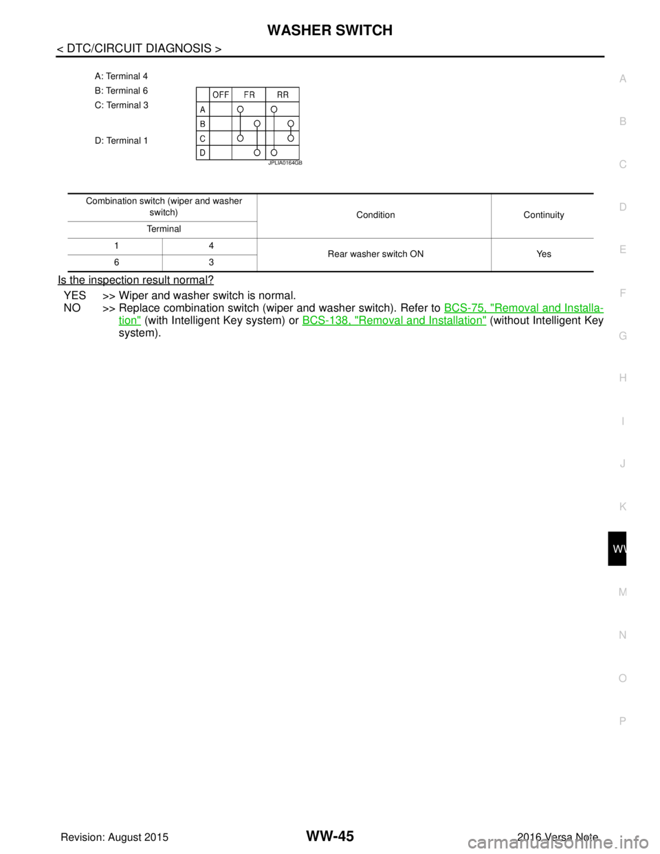
A: Terminal 4
B: Terminal 6
C: Terminal 3
D: Terminal 1
JPLIA0164GB
Combination switch (wiper and washer
switch) ConditionContinuity
Te r m i n a l
14 Rear washer switch ONYes
63
Revision: August 2015 2016 Versa Note
cardiagn.com
Page 3611 of 3641
WW-46
< DTC/CIRCUIT DIAGNOSIS >
REAR WIPER MOTOR CIRCUIT
REAR WIPER MOTOR CIRCUIT
Component Function CheckINFOID:0000000012433225
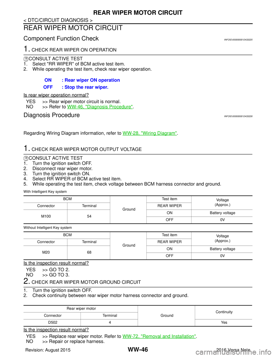
1. CHECK REAR WIPER ON OPERATION
CONSULT ACTIVE TEST
1. Select "RR WIPER" of BCM active test item.
2. While operating the test item, check rear wiper operation.
Is rear wiper operation normal?
YES >> Rear wiper motor circuit is normal.
NO >> Refer to WW-46, "
Diagnosis Procedure".
Diagnosis ProcedureINFOID:0000000012433226
Regarding Wiring Diagram information, refer to WW-28, "Wiring Diagram".
1. CHECK REAR WIPER MOTOR OUTPUT VOLTAGE
CONSULT ACTIVE TEST
1. Turn the ignition switch OFF.
2. Disconnect rear wiper motor.
3. Turn the ignition switch ON.
4. Select RR WIPER of BCM active test item.
5. While operating the test item, check voltage between BCM harness connector and ground.
With Intelligent Key system
Without Intelligent Key system
Is the inspection result normal?
YES >> GO TO 2.
NO >> GO TO 3.
2. CHECK REAR WIPER MOTOR GROUND CIRCUIT
1. Turn the ignition switch OFF.
2. Check continuity between rear wiper motor harness connector and ground.
Is the inspection result normal?
YES >> Replace rear wiper motor. Refer to WW-72, "Removal and Installation".
NO >> Repair or replace harness. ON : Rear wiper ON operation
OFF : Stop the rear wiper.
BCM
GroundTe s t i t e m
Vo l ta g e
(Approx.)
Connector Terminal REAR WIPER
M100 54 ON
Battery voltage
OFF 0V
BCM GroundTe s t i t e m
Vo l ta g e
(Approx.)
Connector Terminal REAR WIPER
M20 68 ON
Battery voltage
OFF 0V
Rear wiper motor
GroundContinuity
Connector Terminal
D502 4 Yes
Revision: August 2015 2016 Versa Note
cardiagn.com
Page 3612 of 3641
REAR WIPER MOTOR CIRCUITWW-47
< DTC/CIRCUIT DIAGNOSIS >
C
DE
F
G H
I
J
K
M A
B
WW
N
O P
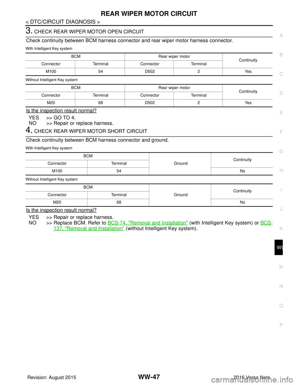
3. CHECK REAR WIPER MOTOR OPEN CIRCUIT
Check continuity between BCM harness connector and rear wiper motor harness connector.
With Intelligent Key system
Without Intelligent Key system
Is the inspection result normal?
YES >> GO TO 4.
NO >> Repair or replace harness.
4. CHECK REAR WIPER MOTOR SHORT CIRCUIT
Check continuity between BCM harness connector and ground.
With Intelligent Key system
Without Intelligent Key system
Is the inspection result normal?
YES >> Repair or replace harness.
NO >> Replace BCM. Refer to BCS-74, "
Removal and Installation" (with Intelligent Key system) or BCS-
137, "Removal and Installation" (without Intelligent Key system).
BCM Rear wiper motor
Continuity
Connector TerminalConnector Terminal
M100 54D502 2Yes
BCM Rear wiper motor
Continuity
Connector TerminalConnector Terminal
M20 68D502 2Yes
BCM
GroundContinuity
Connector Terminal
M100 54 No
BCM GroundContinuity
Connector Terminal
M20 68 No
Revision: August 2015 2016 Versa Note
cardiagn.com
Page 3613 of 3641

WW-48
< DTC/CIRCUIT DIAGNOSIS >
REAR WIPER AUTO STOP SIGNAL CIRCUIT
REAR WIPER AUTO STOP SIGNAL CIRCUIT
Component Function CheckINFOID:0000000012433227
1. CHECK REAR WIPER (AUTO STOP) OPERATION
CONSULT DATA MONITOR
1. Select WIPER of BCM data monitor item.
2. Operate the rear wiper.
3. Check that RR WIPER STOP changes to ON and OFF linked with the wiper operation.
Is the inspection result normal?
YES >> Rear wiper auto stop signal circuit is normal.
NO >> Refer to WW-48, "
Diagnosis Procedure".
Diagnosis ProcedureINFOID:0000000012433228
Regarding Wiring Diagram information, refer to WW-28, "Wiring Diagram".
1. CHECK REAR WIPER MOTOR AUTO STOP CIRCUITS FOR OPEN
1. Turn ignition switch OFF.
2. Disconnect BCM and rear wiper motor.
3. Check continuity between BCM harness connector terminal and rear wiper motor harness connector ter- minal.
With Intelligent Key system
Without Intelligent Key system
Is inspection result normal?
YES >> GO TO 2.
NO >> Repair or replace harness.
2. CHECK AUTO STOP CIRCUITS FOR SHORT TO GROUND
Check continuity between BCM harness connector terminal and ground.
With Intelligent Key system
Without Intelligent Key system
Monitor item ConditionMonitor status
RR WIPER STOP Rear wiper motorStop position
ON
Except stop position OFF
BCM Rear wiper motor
Continuity
Connector Terminal Connector Terminal
M100 44D502 3Yes
BCM Rear wiper motor
Continuity
Connector Terminal Connector Terminal
M20 56D502 3Yes
BCM
GroundContinuity
Connector Terminal
M100 44 No
BCM GroundContinuity
Connector Terminal
M20 56 No
Revision: August 2015 2016 Versa Note
cardiagn.com
Page 3614 of 3641
REAR WIPER AUTO STOP SIGNAL CIRCUITWW-49
< DTC/CIRCUIT DIAGNOSIS >
C
DE
F
G H
I
J
K
M A
B
WW
N
O P
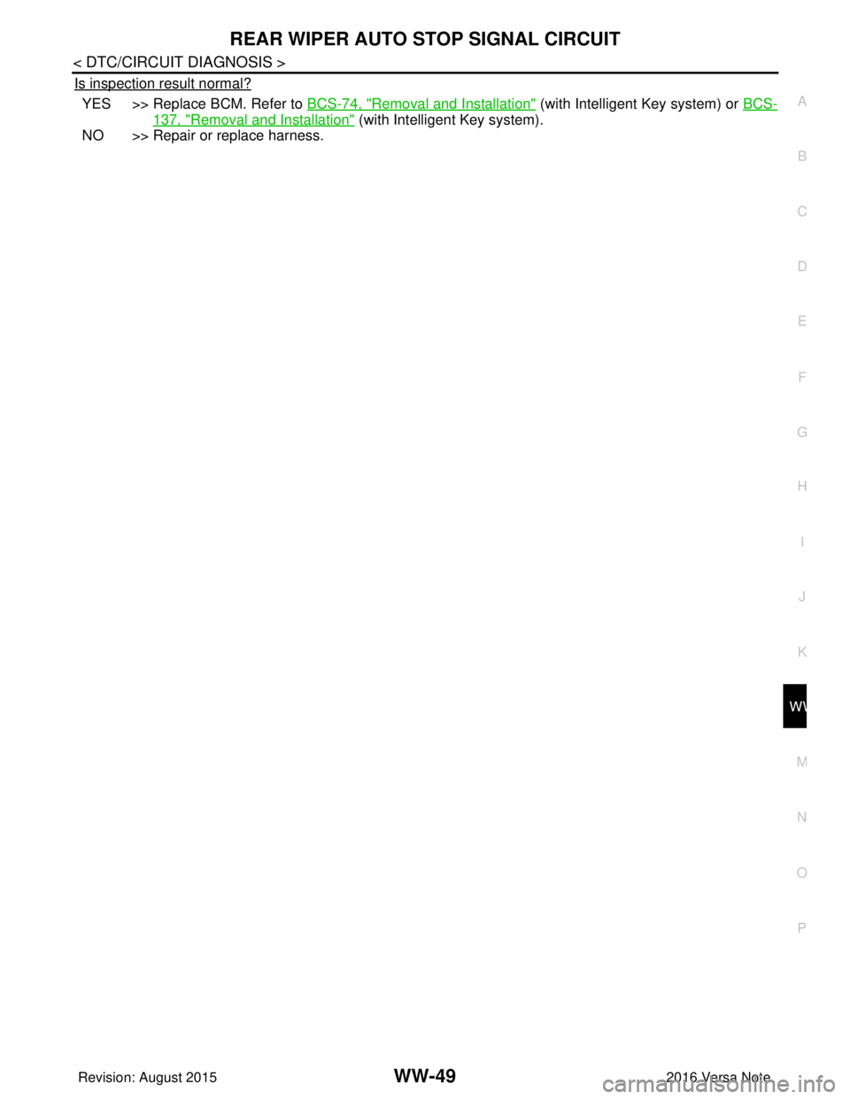
Is inspection result normal?
YES >> Replace BCM. Refer to BCS-74, "Removal and Installation" (with Intelligent Key system) or BCS-
137, "Removal and Installation" (with Intelligent Key system).
NO >> Repair or replace harness.
Revision: August 2015 2016 Versa Note
cardiagn.com
Page 3615 of 3641
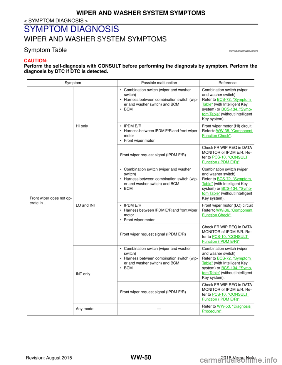
WW-50
< SYMPTOM DIAGNOSIS >
WIPER AND WASHER SYSTEM SYMPTOMS
SYMPTOM DIAGNOSIS
WIPER AND WASHER SYSTEM SYMPTOMS
Symptom TableINFOID:0000000012433229
CAUTION:
Perform the self-diagnosis with CONSULT before performing the diagnosis by symptom. Perform the
diagnosis by DTC if DTC is detected.
SymptomPossible malfunction Reference
Front wiper does not op-
erate in... HI only
• Combination switch (wiper and washer
switch)
• Harness between combination switch (wip- er and washer switch) and BCM
•BCM Combination switch (wiper
and washer switch)
Refer to BCS-72, "
Symptom
Ta b l e" (with Intelligent Key
system) or BCS-134, "
Symp-
tom Table" (without Intelligent
Key system).
• IPDM E/R
• Harness between IPDM E/R and front wiper motor
• Front wiper motor Front wiper motor (HI) circuit
Refer to WW-38, "
Component
Function Check".
Front wiper request signal (IPDM E/R) Check FR WIP REQ in DATA
MONITOR of IPDM E/R. Re-
fer to PCS-10, "
CONSULT
Function (IPDM E/R)".
LO and INT • Combination switch (wiper and washer
switch)
• Harness between combination switch (wip- er and washer switch) and BCM
•BCM Combination switch (wiper
and washer switch)
Refer to BCS-72, "
Symptom
Ta b l e" (with Intelligent Key
system) or BCS-134, "
Symp-
tom Table" (without Intelligent
Key system).
• IPDM E/R
• Harness between IPDM E/R and front wiper motor
• Front wiper motor Front wiper motor (LO) circuit
Refer to WW-36, "
Component
Function Check".
Front wiper request signal (IPDM E/R) Check FR WIP REQ in DATA
MONITOR of IPDM E/R. Re-
fer to PCS-10, "
CONSULT
Function (IPDM E/R)".
INT only • Combination switch (wiper and washer
switch)
• Harness between combination switch (wip- er and washer switch) and BCM
•BCM Combination switch (wiper
and washer switch)
Refer to BCS-72, "
Symptom
Ta b l e" (with Intelligent Key
system) or BCS-134, "
Symp-
tom Table" (without Intelligent
Key system).
Front wiper request signal (IPDM E/R) Check FR WIP REQ in DATA
MONITOR of IPDM E/R. Re-
fer to PCS-10, "
CONSULT
Function (IPDM E/R)".
Any mode —Refer to WW-53, "
Diagnosis
Procedure".
Revision: August 2015
2016 Versa Note
cardiagn.com
Page 3616 of 3641
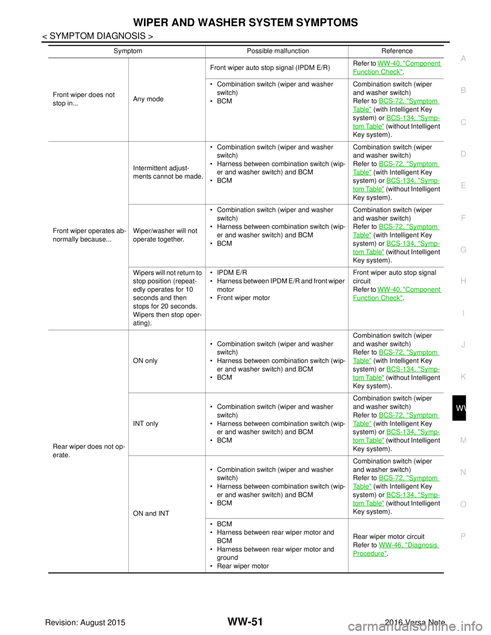
WIPER AND WASHER SYSTEM SYMPTOMSWW-51
< SYMPTOM DIAGNOSIS >
C
DE
F
G H
I
J
K
M A
B
WW
N
O P
Front wiper does not
stop in... Any modeFront wiper auto stop signal (IPDM E/R)
Refer to
WW-40, "
Component
Function Check".
• Combination switch (wiper and washer switch)
•BCM Combination switch (wiper
and washer switch)
Refer to
BCS-72, "
Symptom
Ta b l e" (with Intelligent Key
system) or BCS-134, "
Symp-
tom Table" (without Intelligent
Key system).
Front wiper operates ab-
normally because... Intermittent adjust-
ments cannot be made.
• Combination switch (wiper and washer
switch)
• Harness between combination switch (wip- er and washer switch) and BCM
•BCM Combination switch (wiper
and washer switch)
Refer to
BCS-72, "
Symptom
Ta b l e" (with Intelligent Key
system) or BCS-134, "
Symp-
tom Table" (without Intelligent
Key system).
Wiper/washer will not
operate together. • Combination switch (wiper and washer
switch)
• Harness between combination switch (wip- er and washer switch) and BCM
•BCM Combination switch (wiper
and washer switch)
Refer to
BCS-72, "
Symptom
Ta b l e" (with Intelligent Key
system) or BCS-134, "
Symp-
tom Table" (without Intelligent
Key system).
Wipers will not return to
stop position (repeat-
edly operates for 10
seconds and then
stops for 20 seconds.
Wipers then stop oper-
ating). • IPDM E/R
• Harness between IPDM E/R and front wiper
motor
• Front wiper motor Front wiper auto stop signal
circuit
Refer to
WW-40, "
Component
Function Check".
Rear wiper does not op-
erate. ON only
• Combination switch (wiper and washer
switch)
• Harness between combination switch (wip-
er and washer switch) and BCM
•BCM Combination switch (wiper
and washer switch)
Refer to
BCS-72, "
Symptom
Ta b l e" (with Intelligent Key
system) or BCS-134, "
Symp-
tom Table" (without Intelligent
Key system).
INT only • Combination switch (wiper and washer
switch)
• Harness between combination switch (wip- er and washer switch) and BCM
•BCM Combination switch (wiper
and washer switch)
Refer to
BCS-72, "
Symptom
Ta b l e" (with Intelligent Key
system) or BCS-134, "
Symp-
tom Table" (without Intelligent
Key system).
ON and INT • Combination switch (wiper and washer
switch)
• Harness between combination switch (wip- er and washer switch) and BCM
•BCM Combination switch (wiper
and washer switch)
Refer to
BCS-72, "
Symptom
Ta b l e" (with Intelligent Key
system) or BCS-134, "
Symp-
tom Table" (without Intelligent
Key system).
•BCM
• Harness between rear wiper motor and BCM
• Harness between rear wiper motor and ground
• Rear wiper motor Rear wiper motor circuit
Refer to
WW-46, "
Diagnosis
Procedure".
Symptom
Possible malfunction Reference
Revision: August 2015 2016 Versa Note
cardiagn.com
Page 3617 of 3641
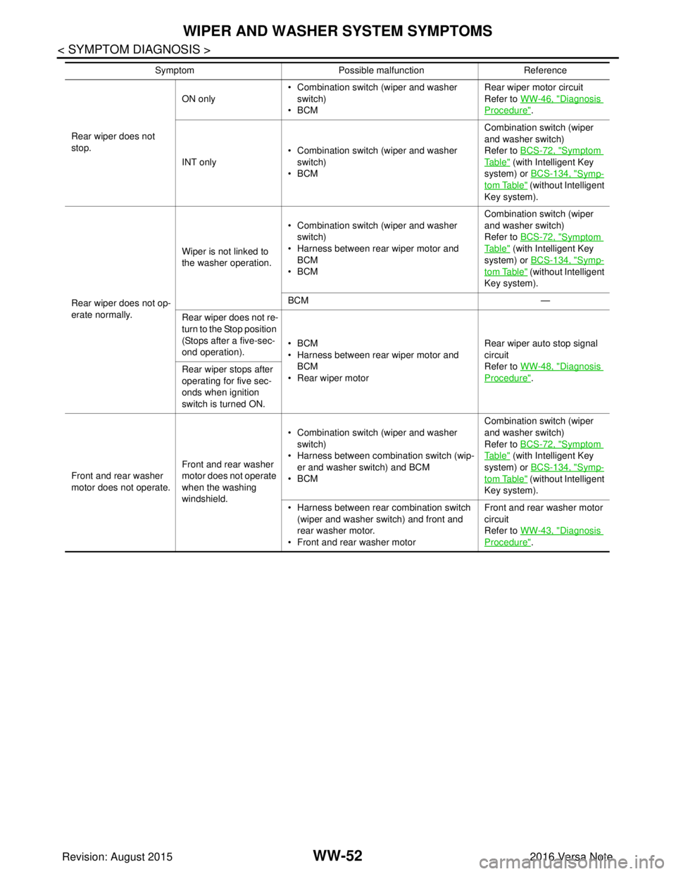
WW-52
< SYMPTOM DIAGNOSIS >
WIPER AND WASHER SYSTEM SYMPTOMS
Rear wiper does not
stop.ON only
• Combination switch (wiper and washer
switch)
•BCM Rear wiper motor circuit
Refer to WW-46, "
Diagnosis
Procedure".
INT only • Combination switch (wiper and washer
switch)
•BCM Combination switch (wiper
and washer switch)
Refer to BCS-72, "
Symptom
Ta b l e" (with Intelligent Key
system) or BCS-134, "
Symp-
tom Table" (without Intelligent
Key system).
Rear wiper does not op-
erate normally. Wiper is not linked to
the washer operation.
• Combination switch (wiper and washer
switch)
• Harness between rear wiper motor and BCM
•BCM Combination switch (wiper
and washer switch)
Refer to BCS-72, "
Symptom
Ta b l e" (with Intelligent Key
system) or BCS-134, "
Symp-
tom Table" (without Intelligent
Key system).
BCM —
Rear wiper does not re-
turn to the Stop position
(Stops after a five-sec-
ond operation). •BCM
• Harness between rear wiper motor and
BCM
• Rear wiper motor Rear wiper auto stop signal
circuit
Refer to WW-48, "
Diagnosis
Procedure".
Rear wiper stops after
operating for five sec-
onds when ignition
switch is turned ON.
Front and rear washer
motor does not operate. Front and rear washer
motor does not operate
when the washing
windshield.• Combination switch (wiper and washer
switch)
• Harness between combination switch (wip- er and washer switch) and BCM
•BCM Combination switch (wiper
and washer switch)
Refer to BCS-72, "
Symptom
Ta b l e" (with Intelligent Key
system) or BCS-134, "
Symp-
tom Table" (without Intelligent
Key system).
• Harness between rear combination switch (wiper and washer switch) and front and
rear washer motor.
• Front and rear washer motor Front and rear washer motor
circuit
Refer to WW-43, "
Diagnosis
Procedure".
Symptom
Possible malfunction Reference
Revision: August 2015 2016 Versa Note
cardiagn.com