2016 NISSAN NOTE key
[x] Cancel search: keyPage 3560 of 3641
WCS
KEY SWITCH SIGNAL CIRCUIT (WITHOUT INTELLIGENT KEY)
WCS-45
< DTC/CIRCUIT DIAGNOSIS >
C
D E
F
G H
I
J
K L
M B A
O P
KEY SWITCH SIGNAL CIRCUIT (WITHOUT INTELLIGENT KEY)
DescriptionINFOID:0000000012432706
Transmits a key switch signal to the BCM.
Component Function CheckINFOID:0000000012432707
1. CHECK BCM INPUT SIGNAL
Select Data Monitor for BCM and check the KEY ON SW monitor value.
Is the inspection result normal?
YES >> Inspection End.
NO >> Refer to WCS-45, "
DiagnosisProcedure".
Diagnosis ProcedureINFOID:0000000012432708
Regarding Wiring Diagram information, refer to WCS-26, "Wiring Diagram".
1. CHECK FUSE
Check if the key switch 10A fuse [No. 8, located in the fuse block (J/B)] is blown.
Is the fuse blown?
YES >> Replace the fuse after repairing the affected circuit.
NO >> GO TO 2.
2. CHECK BCM INPUT SIGNAL
Check voltage between BCM harness connector M18 terminal 37 and ground.
Is the inspection result normal?
YES >> Inspection End.
NO >> GO TO 3.
3. CHECK KEY SWITCH CIRCUIT
1. Disconnect BCM connector M18 and key switch.
2. Check continuity between BCM harness connector M18 terminal 37 and key switch harness connector M27 terminal 1.
3. Check continuity between BCM harness connector M18 terminal 37 and ground.
Monitor Item Condition Status
KEY ON SW When key is removed from key cylinder
OFF
When key is inserted into key cylinder ON
Te r m i n a l s
ConditionVol tag e
(Approx.)
(+)
(−)
BCM
connector Te r m i n a l
M18 37Ground Key is inserted
Battery voltage
Key is removed 0V
BCM Key switch
Continuity
Connector TerminalConnector Terminal
M 183 7M 27 1 Y es
Revision: August 2015 2016 Versa Note
cardiagn.com
Page 3561 of 3641

WCS-46
< DTC/CIRCUIT DIAGNOSIS >
KEY SWITCH SIGNAL CIRCUIT (WITHOUT INTELLIGENT KEY)
Is the inspection result normal?
YES >> GO TO 4.
NO >> Repair or replace harness.
4. CHECK KEY SWITCH POWER SUPPLY CIRCUIT
Check voltage between key switch harness connector M27 terminal 2 and ground.
Is the inspection result normal?
YES >> Replace key switch.
NO >> Repair or replace harness.
Component InspectionINFOID:0000000012432709
1. CHECK KEY SWITCH
1. Turn ignition switch OFF.
2. Disconnect key switch.
3. Check continuity between key switch terminals 1 and 2.
Is the inspection result normal?
YES >> Inspection End.
NO >> Replace key switch.
BCM
GroundContinuity
Connector Terminal
M18 37 No
Te r m i n a l s
Vo l ta g e
(Approx.)
(+)
(–)
Key switch Terminal
M27 2Ground Battery voltage
Terminal ConditionContinuity
12 When key is removed from key cylinder
No
When key is inserted into key cylinder Yes
Revision: August 2015 2016 Versa Note
cardiagn.com
Page 3563 of 3641
WCS-48
< SYMPTOM DIAGNOSIS >
THE SEAT BELT REMINDER WARNING CONTINUES SOUNDING, OR DOES
NOT SOUND
THE SEAT BELT REMINDER WARN ING CONTINUES SOUNDING, OR
DOES NOT SOUND
DescriptionINFOID:0000000012432712
• Seat belt reminder warning does not sound.
• Seat belt reminder warning sounds continuously.
Diagnosis ProcedureINFOID:0000000012432713
NOTE:
To identify combination meter type, refer to WCS-3, "
Information".
1.CHECK WARNING CHIME OPERATION
1. Select “BUZZER” of “BCM” using CONSULT.
2. Perform “SEAT BELT WARN TEST” in “Active Test”.
Is the inspection result normal?
YES >> GO TO 2.
NO >> Replace combination meter. Refer to MWI-54, "
Removal and Installation" (Type A) or MWI-115,
"Removal and Installation" (Type B).
2.CHECK SEAT BELT WARNING LAMP
1. Turn ignition switch ON.
2. Check the operation of the seat belt warning lamp in the combination meter.
Is the inspection result normal?
YES >> Replace BCM. Refer to BCS-74, "Removal and Installation" (with Intelligent Key system) or BCS-
137, "Removal and Installation" (without Intelligent Key system).
NO >> GO TO 3.
3.CHECK SEAT BELT BUCKLE SWITCH LH CIRCUIT
Check the seat belt buckle switch LH circuit. Refer to WCS-39, "
TYPE A : DiagnosisProcedure" (Type A) or
WCS-40, "
TYPE B : DiagnosisProcedure" (Type B).
Is the inspection result normal?
YES >> GO TO 4.
NO >> Repair or replace harness or connector.
4.CHECK SEAT BELT BUCKLE SWITCH LH
Check the seat belt buckle switch LH. Refer to WCS-40, "
TYPE A : Component Inspection" (Type A) or WCS-
41, "TYPE B : Component Inspection" (Type B).
Is the inspection result normal?
YES >> Replace combination meter. Refer to MWI-54, "Removal and Installation" (Type A) or MWI-115,
"Removal and Installation" (Type B).
NO >> Replace the seat belt buckle switch LH. Refer to SR-35, "
Removal and Installation".
Condition Seat belt warning lamp
Driver seat belt fastened OFF
Driver seat belt not fastened ON
Revision: August 2015 2016 Versa Note
cardiagn.com
Page 3564 of 3641
WCS
THE LIGHT REMINDER WARNING DOES NOT SOUNDWCS-49
< SYMPTOM DIAGNOSIS >
C
DE
F
G H
I
J
K L
M B A
O P
THE LIGHT REMINDER WA RNING DOES NOT SOUND
DescriptionINFOID:0000000012432714
Light reminder warning chime does not sound even though headlamps are illuminated.
Diagnosis ProcedureINFOID:0000000012432715
1.CHECK COMBINATION SWITCH (L IGHTING SWITCH) OPERATION
Check that the headlamps operate normally by operat ing the combination switch (lighting switch).
Do they operate normally?
YES >> GO TO 2.
NO >> Refer to WCS-32, "
Work Flow".
2.CHECK FRONT DOOR SWITCH LH SIGNAL CIRCUIT
Check the front door switch LH signal circuit. Refer to DLK-98, "
Diagnosis Procedure" (with Intelligent Key
system) or DLK-232, "
Diagnosis Procedure" (without Intelligent Key system).
Is the inspection result normal?
YES >> GO TO 3.
NO >> Repair or replace harness or connector.
3.CHECK FRONT DOOR SWITCH LH
Check the front door switch LH. Refer to DLK-99, "
Component Inspection" (with Intelligent Key system) or
DLK-234, "
Component Inspection" (without Intelligent Key system).
Is the inspection result normal?
YES >> Replace BCM. Refer to BCS-74, "Removal and Installation" (with Intelligent Key system) or BCS-
137, "Removal and Installation" (without Intelligent Key system).
NO >> Replace front door switch LH. Refer to DLK-181, "
Removal and Installation" (with Intelligent Key
system) or DLK-308, "
Removal and Installation" (without Intelligent Key system).
Revision: August 2015 2016 Versa Note
cardiagn.com
Page 3565 of 3641
WCS-50
< SYMPTOM DIAGNOSIS >
THE KEY WARNING DOES NOT SOUND (WITHOUT INTELLIGENT KEY)
THE KEY WARNING DOES NOT SOUN D (WITHOUT INTELLIGENT KEY)
DescriptionINFOID:0000000012432716
The key warning chime does not sound, when all of the following conditions are fulfilled.
• Key inserted into the key cylinder (key switch signal ON).
• Ignition switch is in ACC or OFF (ignition switch signal OFF).
• Driver side door is open (front door switch LH ON)
Diagnosis ProcedureINFOID:0000000012432717
1.CHECK BCM INPUT SIGNAL
1. Connect CONSULT.
2. Select the “Data Monitor” of “BCM (BUZZER)” and check t he “KEY ON SW” monitor value.
Is the inspection result normal?
YES >> Replace BCM. Refer to BCS-137, "Removal and Installation".
NO >> GO TO 2.
2.CHECK KEY SWITCH SIGNAL CIRCUIT
Check the key switch signal circuit. Refer to WCS-45, "
DiagnosisProcedure".
Is the inspection result normal?
YES >> GO TO 3.
NO >> Repair or replace harness or connector.
3.CHECK KEY SWITCH
Check the key switch. Refer to WCS-46, "
Component Inspection".
Is the inspection result normal?
YES >> Replace BCM. Refer to BCS-137, "Removal and Installation".
NO >> Replace key switch.
Monitor item Condition Status
KEY ON SW Under the condition of buzzer input
On
Except above Off
Revision: August 2015 2016 Versa Note
cardiagn.com
Page 3566 of 3641

WW-1
DRIVER CONTROLS
C
DE
F
G H
I
J
K
M
SECTION WW
A
B
WW
N
O P
CONTENTS
WIPER & WASHER
PRECAUTION ....... ........................................3
PRECAUTIONS .............................................. .....3
Precaution for Supplemental Restraint System
(SRS) "AIR BAG" and "SEAT BELT PRE-TEN-
SIONER" ............................................................. ......
3
Procedure without Cowl Top Cover .......................3
Precaution for Work ..................................................3
PREPARATION ............................................5
PREPARATION .............................................. .....5
Special Service Tools .......................................... ......5
Commercial Service Tool ..........................................5
SYSTEM DESCRIPTION ..............................6
COMPONENT PARTS ................................... .....6
Component Parts Location .................................. ......6
SYSTEM ..............................................................8
FRONT WIPER AND WASHER SYSTEM ............. ......8
FRONT WIPER AND WASHER SYSTEM : Sys-
tem Diagram ..............................................................
8
FRONT WIPER AND WASHER SYSTEM : Sys-
tem Description .........................................................
8
FRONT WIPER AND WASHER SYSTEM : Fail-
Safe .........................................................................
10
REAR WIPER AND WASHER SYSTEM ............... ....10
REAR WIPER AND WASHER SYSTEM : System
Diagram ...................................................................
10
REAR WIPER AND WASHER SYSTEM : System
Description ..............................................................
10
DIAGNOSIS SYSTEM (BCM) (WITH INTELLI-
GENT KEY SYSTEM) .........................................
13
COMMON ITEM ..................................................... ....13
COMMON ITEM : CONSULT Function (BCM -
COMMON ITEM) .....................................................
13
WIPER .................................................................... ....14
WIPER : CONSULT Function (BCM - WIPER) .......14
DIAGNOSIS SYSTEM (BCM) (WITHOUT IN-
TELLIGENT KEY SYSTEM) .............................
15
COMMON ITEM ..................................................... ....15
COMMON ITEM : CONSULT Function (BCM -
COMMON ITEM) .....................................................
15
WIPER .................................................................... ....16
WIPER : CONSULT Function (BCM - WIPER) .......16
DIAGNOSIS SYSTEM (IPDM E/R) ...................17
Diagnosis Description ..............................................17
CONSULT Function (IPDM E/R) .............................18
ECU DIAGNOSIS INFORMATION ..............21
BCM, IPDM E/R .................................................21
List of ECU Reference ......................................... ....21
WIRING DIAGRAM ......................................22
FRONT WIPER AND WASHER SYSTEM ........22
Wiring Diagram .................................................... ....22
REAR WIPER AND WASHER SYSTEM ..........28
Wiring Diagram ........................................................28
BASIC INSPECTION ...................................33
DIAGNOSIS AND REPAIR WORKFLOW ........33
Work Flow ............................................................ ....33
DTC/CIRCUIT DIAGNOSIS .........................35
WIPER AND WASHER FUSE ...........................35
Description ........................................................... ....35
Diagnosis Procedure ...............................................35
FRONT WIPER MOTOR LO CIRCUIT ..............36
Component Function Check ....................................36
Diagnosis Procedure ...............................................36
Revision: August 2015 2016 Versa Note
cardiagn.com
Page 3572 of 3641
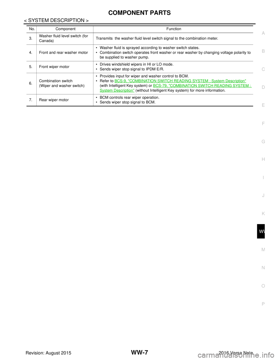
COMPONENT PARTSWW-7
< SYSTEM DESCRIPTION >
C
DE
F
G H
I
J
K
M A
B
WW
N
O P
3. Washer fluid level switch (for
Canada) Transmits the washer fluid level switch signal to the combination meter.
4. Front and rear washer motor • Washer fluid is sprayed according to washer switch states.
• Combination switch operates front washer or rear washer by changing voltage polarity to
be supplied to washer pump.
5. Front wiper motor • Drives windshield wipers in HI or LO mode.
• Sends wiper stop signal to IPDM E/R.
6. Combination switch
(Wiper and washer switch) • Provides input for wiper and washer control to BCM.
• Refer to
BCS-9, "
COMBINATION SWITCH READING SYSTEM : System Description"
(with Intelligent Key system) or BCS-79, "
COMBINATION SWITCH READING SYSTEM :
System Description" (without Intelligent Key system) for more information.
7. Rear wiper motor • BCM controls rear wiper operation.
• Sends wiper stop signal to BCM.
No.
Component Function
Revision: August 2015 2016 Versa Note
cardiagn.com
Page 3577 of 3641

WW-12
< SYSTEM DESCRIPTION >
SYSTEM
BCM performs the fail-safe function when the rear wiper auto stop circuit is malfunctioning. Refer to BCS-48,
"Fail-safe" (with Intelligent Key system) or BCS-115, "Fail-safe" (without Intelligent Key system).
Revision: August 2015 2016 Versa Note
cardiagn.com