2016 NISSAN NOTE key
[x] Cancel search: keyPage 3181 of 3641

S CONNECTOR CIRCUITSTR-29
< DTC/CIRCUIT DIAGNOSIS >
C
DE
F
G H
I
J
K L
M A
STR
NP
O
S CONNECTOR CIRCUIT
DescriptionINFOID:0000000012432074
The starter motor magnetic switch is supplied with power when the ignition switch is turned to the START posi-
tion while the selector lever is in the P (Park) or N (Neutral) position.
Diagnosis ProcedureINFOID:0000000012432075
Regarding Wiring Diagram information, refer to
STR-10, "Wiring Diagram - With Intelligent Key System" or
STR-16, "
Wiring Diagram - Without Intelligent Key System".
CAUTION:
Perform diagnosis under the cond ition that engine cannot start by the following procedure.
1. Remove fuel pump fuse.
2. Crank or start the engine (where possi ble) until the fuel pressure is released.
1.CHECK “S” CONNECTOR CIRCUIT
1. Turn ignition switch OFF.
2. Disconnect starter motor connector.
3. Shift selector lever to “P” (Park) or “N” (Neutral) position.
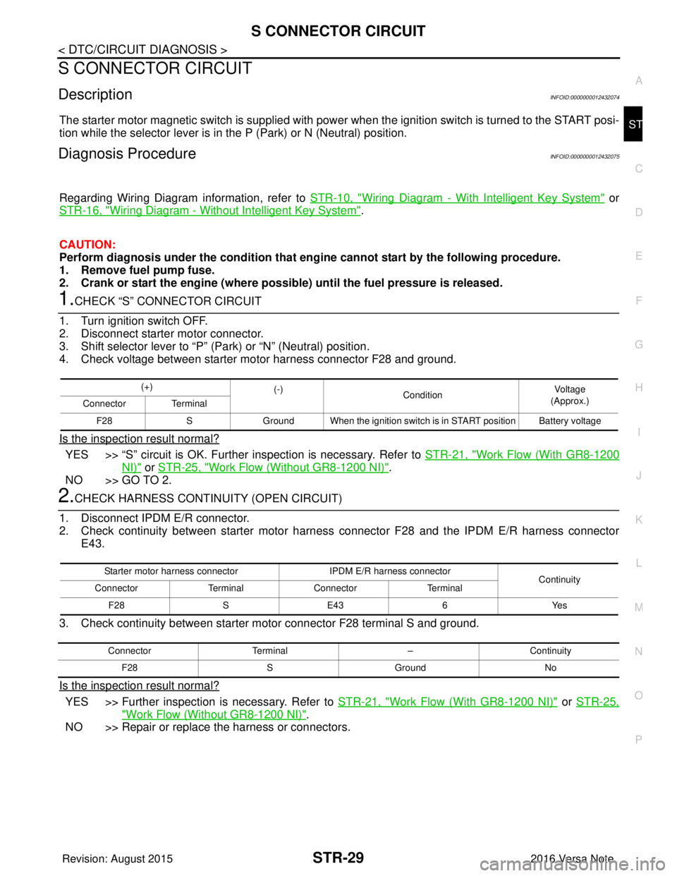
4. Check voltage between starter motor harness connector F28 and ground.
Is the inspection result normal?
YES >> “S” circuit is OK. Further inspection is necessary. Refer to STR-21, "Work Flow (With GR8-1200
NI)" or STR-25, "Work Flow (Without GR8-1200 NI)".
NO >> GO TO 2.
2.CHECK HARNESS CONTINUI TY (OPEN CIRCUIT)
1. Disconnect IPDM E/R connector.
2. Check continuity between starter motor harnes s connector F28 and the IPDM E/R harness connector
E43.
3. Check continuity between starter motor connector F28 terminal S and ground.
Is the inspection result normal?
YES >> Further inspection is necessary. Refer to STR-21, "Work Flow (With GR8-1200 NI)" or STR-25,
"Work Flow (Without GR8-1200 NI)".
NO >> Repair or replace the harness or connectors.
(+) (-)
Condition Voltage
(Approx.)
Connector Terminal
F28 SGround When the ignition switch is in START position Battery voltage
Starter motor harness connector IPDM E/R harness connector
Continuity
Connector TerminalConnector Terminal
F28 SE43 6Yes
Connector Terminal –Continuity
F28 SGround No
Revision: August 2015 2016 Versa Note
cardiagn.com
Page 3230 of 3641

STEERING COLUMNST-9
< REMOVAL AND INSTALLATION >
C
DE
F
H I
J
K L
M A
B
ST
N
O P
STEERING COLUMN
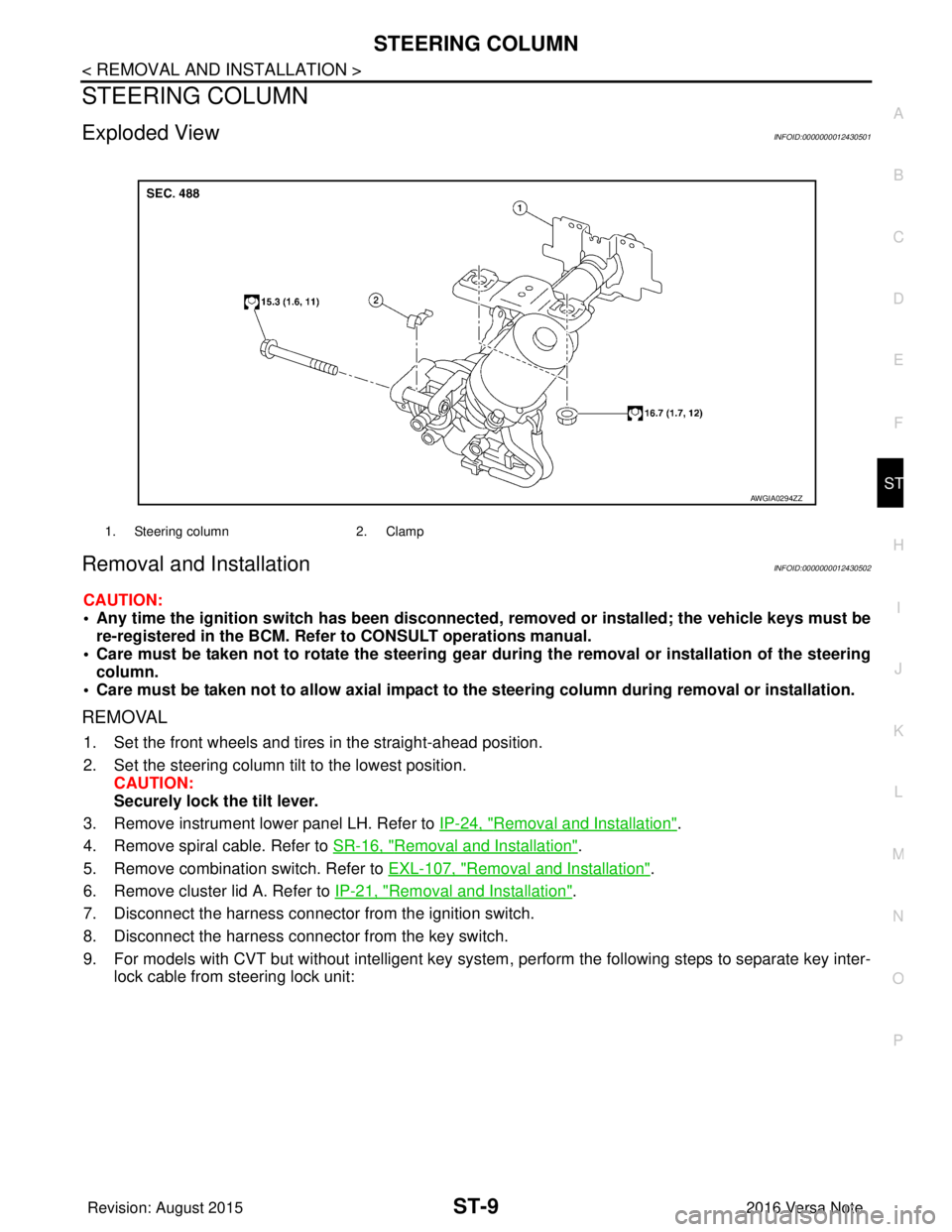
Exploded ViewINFOID:0000000012430501
Removal and InstallationINFOID:0000000012430502
CAUTION:
• Any time the ignition switch has been disconnected, removed or installed; the vehicle keys must be
re-registered in the BCM. Refer to CONSULT operations manual.
• Care must be taken not to rotate the steering gear during the removal or inst allation of the steering
column.
• Care must be taken not to allow axial impact to the steering column during removal or installation.
REMOVAL
1. Set the front wheels and tires in the straight-ahead position.
2. Set the steering column tilt to the lowest position.
CAUTION:
Securely lock the tilt lever.
3. Remove instrument lower panel LH. Refer to IP-24, "
Removal and Installation".
4. Remove spiral cable. Refer to SR-16, "
Removal and Installation".
5. Remove combination switch. Refer to EXL-107, "
Removal and Installation".
6. Remove cluster lid A. Refer to IP-21, "
Removal and Installation".
7. Disconnect the harness connector from the ignition switch.
8. Disconnect the harness connector from the key switch.
9. For models with CVT but without intelligent key system , perform the following steps to separate key inter-
lock cable from steering lock unit:
1. Steering column 2. Clamp
AWGIA0294ZZ
Revision: August 2015 2016 Versa Note
cardiagn.com
Page 3231 of 3641

ST-10
< REMOVAL AND INSTALLATION >
STEERING COLUMN
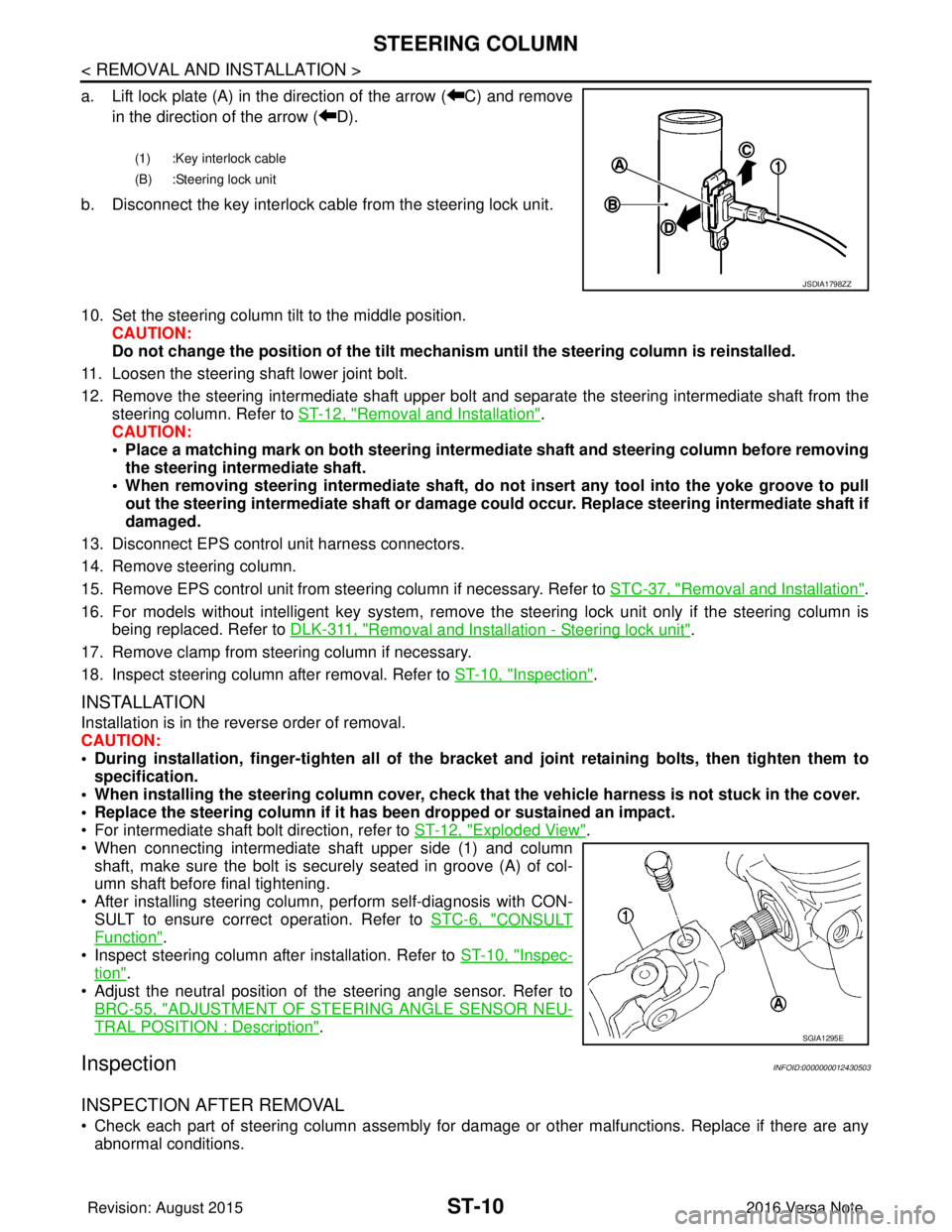
a. Lift lock plate (A) in the direction of the arrow ( C) and removein the direction of the arrow ( D).
b. Disconnect the key interlock cable from the steering lock unit.
10. Set the steering column tilt to the middle position. CAUTION:
Do not change the position of the tilt mechanism until the steering column is reinstalled.
11. Loosen the steering shaft lower joint bolt.
12. Remove the steering intermediate shaft upper bolt and separate the steering intermediate shaft from the
steering column. Refer to ST-12, "
Removal and Installation".
CAUTION:
• Place a matching mark on both steering interme diate shaft and steering column before removing
the steering intermediate shaft.
• When removing steering intermedi ate shaft, do not insert any tool into the yoke groove to pull
out the steering intermediate shaft or damage could occur. Replace steering intermediate shaft if
damaged.
13. Disconnect EPS control unit harness connectors.
14. Remove steering column.
15. Remove EPS control unit from steering column if necessary. Refer to STC-37, "
Removal and Installation".
16. For models without intelligent key system, remove the steering lock unit only if the steering column is being replaced. Refer to DLK-311, "
Removal and Installation - Steering lock unit".
17. Remove clamp from steering column if necessary.
18. Inspect steering column after removal. Refer to ST-10, "
Inspection".
INSTALLATION
Installation is in the reverse order of removal.
CAUTION:
• During installation, finger-tighten all of the bracket and joint retaining bolts, then tighten them to
specification.
• When installing the steering colu mn cover, check that the vehicle harness is not stuck in the cover.
• Replace the steering column if it has been dropped or sustained an impact.
• For intermediate shaft bolt direction, refer to ST-12, "
Exploded View".
• When connecting intermediate shaft upper side (1) and column shaft, make sure the bolt is securely seated in groove (A) of col-
umn shaft before final tightening.
• After installing steering column, perform self-diagnosis with CON- SULT to ensure correct operation. Refer to STC-6, "
CONSULT
Function".
• Inspect steering column after installation. Refer to ST-10, "
Inspec-
tion".
• Adjust the neutral position of the steering angle sensor. Refer to
BRC-55, "
ADJUSTMENT OF STEERI NG ANGLE SENSOR NEU-
TRAL POSITION : Description".
InspectionINFOID:0000000012430503
INSPECTION AFTER REMOVAL
• Check each part of steering column assembly for damage or other malfunctions. Replace if there are any
abnormal conditions.
(1) :Key interlock cable
(B) :Steering lock unit
JSDIA1798ZZ
SGIA1295E
Revision: August 2015 2016 Versa Note
cardiagn.com
Page 3243 of 3641

TM-2
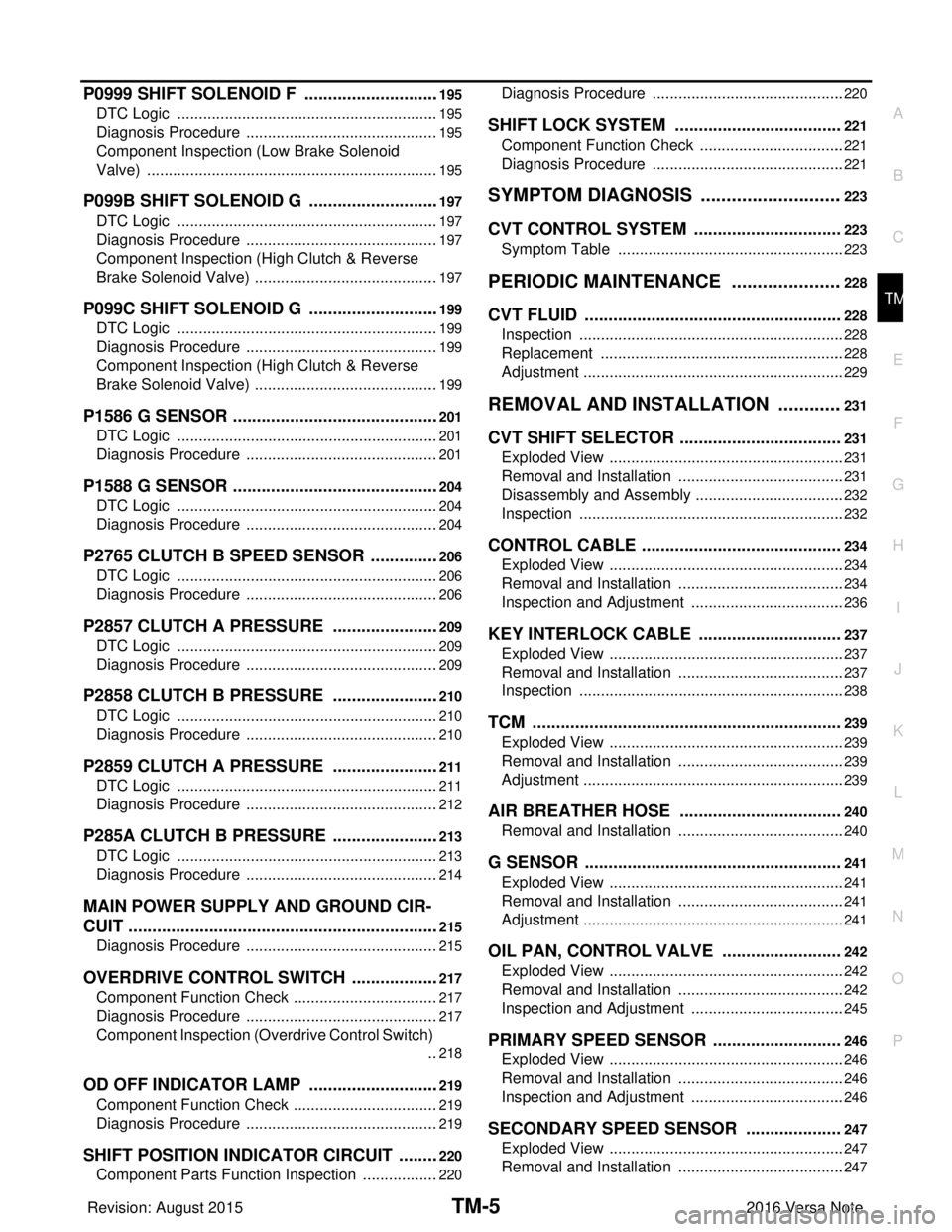
INPUT SHAFT AND GEAR ...............................45
Exploded View ..................................................... ...45
Disassembly ...........................................................45
Assembly ................................................................45
Inspection ...............................................................45
MAINSHAFT AND GEAR ..................................47
Exploded View ..................................................... ...47
Disassembly ...........................................................47
Assembly ................................................................49
Inspection ...............................................................50
FINAL DRIVE .....................................................52
Exploded View ..................................................... ...52
Disassembly ...........................................................52
Assembly ................................................................52
Inspection ...............................................................52
SERVICE DATA AND SPECIFICATIONS
(SDS) ........................................................ ...
54
SERVICE DATA AND SPECIFICATIONS
(SDS) ............................................................... ...
54
General Specifications ......................................... ...54
CVT: RE0F11A
PRECAUTION .............. ...............................
55
PRECAUTIONS .............................................. ...55
Precaution for Supplemental Restraint System
(SRS) "AIR BAG" and "SEAT BELT PRE-TEN-
SIONER" .............................................................. ...
55
Precaution for Procedure without Cowl Top Cover ...55
Precaution for TCM, Transaxle Assembly or Con-
trol Valve Replacement ..........................................
55
Precaution for G Sensor Removal/Installation or
Replacement ..........................................................
55
General Precautions ...............................................56
On Board Diagnosis (OBD) System of CVT and
Engine ....................................................................
57
Removal and Installation Procedure for CVT Unit
Connector ...............................................................
57
PREPARATION ...........................................59
PREPARATION .............................................. ...59
Special Service Tools .......................................... ...59
Commercial Service Tools ......................................59
SYSTEM DESCRIPTION ............................61
COMPONENT PARTS .................................... ...61
CVT CONTROL SYSTEM ...................................... ...61
CVT CONTROL SYSTEM : Component Parts Lo-
cation ......................................................................
61
CVT CONTROL SYSTEM : TCM ...........................63
CVT CONTROL SYSTEM : ROM Assembly ....... ...63
CVT CONTROL SYSTEM : Transmission Range
Switch .................................................................. ...
63
CVT CONTROL SYSTEM : Primary Speed Sen-
sor ........................................................................ ...
63
CVT CONTROL SYSTEM : Secondary Speed
Sensor .....................................................................
63
CVT CONTROL SYSTEM : Output Speed Sensor ...64
CVT CONTROL SYSTEM : CVT Fluid Tempera-
ture Sensor .......................................................... ...
64
CVT CONTROL SYSTEM : Secondary Pressure
Sensor .................................................................. ...
65
CVT CONTROL SYSTEM : Primary Pressure So-
lenoid Valve ......................................................... ...
65
CVT CONTROL SYSTEM : Low Brake Solenoid
Valve .......................................................................
65
CVT CONTROL SYSTEM : High Clutch & Re-
verse Brake Solenoid Valve ....................................
66
CVT CONTROL SYSTEM : Torque Converter
Clutch Solenoid Valve .............................................
66
CVT CONTROL SYSTEM : Line Pressure Sole-
noid Valve ............................................................ ...
66
CVT CONTROL SYSTEM : G Sensor ....................66
CVT CONTROL SYSTEM : Overdrive Control
Switch .....................................................................
66
CVT CONTROL SYSTEM : O/D OFF Indicator
Lamp .......................................................................
66
CVT CONTROL SYSTEM : Shift Position Indica-
tor ............................................................................
68
CVT CONTROL SYSTEM : Malfunction Indicator
Lamp (MIL) ..............................................................
68
SHIFT LOCK SYSTEM ..............................................68
SHIFT LOCK SYSTEM : Co mponent Parts Loca-
tion ....................................................................... ...
68
STRUCTURE AND OPERATION ......................70
TRANSAXLE .......................................................... ...70
TRANSAXLE : Cross-Sectional View .....................70
TRANSAXLE : Transaxle Mechanism ... .................70
TRANSAXLE : Operation Stat us .............................72
TRANSAXLE : Oil Pressure System .......................73
TRANSAXLE : Component De scription ..................73
FLUID COOLER & FLUID WARMER SYSTEM ..... ...74
FLUID COOLER & FLUID WARMER SYSTEM :
System Description .................................................
74
SHIFT LOCK SYSTEM ..............................................74
SHIFT LOCK SYSTEM : Syst em Description .........75
KEY LOCK SYSTEM .............................................. ...75
KEY LOCK SYSTEM : System Description ............75
SYSTEM ......................................................... ...76
CVT CONTROL SYSTEM .........................................76
CVT CONTROL SYSTEM : System Description . ...76
CVT CONTROL SYSTEM : Fail-safe ......................78
CVT CONTROL SYSTEM : Protection Control .......80
LINE PRESSURE CONTROL ................................ ...81
LINE PRESSURE CONTROL : System Descrip-
tion ....................................................................... ...
82
Revision: August 2015 2016 Versa Note
cardiagn.com
Page 3246 of 3641

TM-5
CEF
G H
I
J
K L
M A
B
TM
N
O P
P0999 SHIFT SOLENOID F .............................195
DTC Logic ........................................................... ..195
Diagnosis Procedure .............................................195
Component Inspection (Low Brake Solenoid
Valve) ....................................................................
195
P099B SHIFT SOLENOID G ............................197
DTC Logic ........................................................... ..197
Diagnosis Procedure .............................................197
Component Inspection (High Clutch & Reverse
Brake Solenoid Valve) ...........................................
197
P099C SHIFT SOLENOID G ............................199
DTC Logic ........................................................... ..199
Diagnosis Procedure .............................................199
Component Inspection (High Clutch & Reverse
Brake Solenoid Valve) ...........................................
199
P1586 G SENSOR ............................................201
DTC Logic .............................................................201
Diagnosis Procedure .............................................201
P1588 G SENSOR ............................................204
DTC Logic .............................................................204
Diagnosis Procedure .............................................204
P2765 CLUTCH B SPEED SENSOR ...............206
DTC Logic ........................................................... ..206
Diagnosis Procedure .............................................206
P2857 CLUTCH A PRESSURE .......................209
DTC Logic ........................................................... ..209
Diagnosis Procedure .............................................209
P2858 CLUTCH B PRESSURE .......................210
DTC Logic ........................................................... ..210
Diagnosis Procedure .............................................210
P2859 CLUTCH A PRESSURE .......................211
DTC Logic ........................................................... ..211
Diagnosis Procedure .............................................212
P285A CLUTCH B PRESSURE .......................213
DTC Logic ........................................................... ..213
Diagnosis Procedure .............................................214
MAIN POWER SUPPLY AND GROUND CIR-
CUIT ..................................................................
215
Diagnosis Procedure ........................................... ..215
OVERDRIVE CONTROL SWITCH ...................217
Component Function Check ................................ ..217
Diagnosis Procedure .............................................217
Component Inspection (Overdrive Control Switch)
..
218
OD OFF INDICATOR LAMP ............................219
Component Function Check ..................................219
Diagnosis Procedure .............................................219
SHIFT POSITION INDICATOR CIRCUIT .........220
Component Parts Function Inspection ................ ..220
Diagnosis Procedure ........................................... ..220
SHIFT LOCK SYSTEM ...................................221
Component Function Check ..................................221
Diagnosis Procedure .............................................221
SYMPTOM DIAGNOSIS ............................223
CVT CONTROL SYSTEM ...............................223
Symptom Table ................................................... ..223
PERIODIC MAINTENANCE ......................228
CVT FLUID ......................................................228
Inspection ............................................................ ..228
Replacement .........................................................228
Adjustment .............................................................229
REMOVAL AND INSTALLATION .............231
CVT SHIFT SELECTOR ..................................231
Exploded View ..................................................... ..231
Removal and Installation .......................................231
Disassembly and Assembly ...................................232
Inspection ..............................................................232
CONTROL CABLE ..........................................234
Exploded View .......................................................234
Removal and Installation .......................................234
Inspection and Adjustment ....................................236
KEY INTERLOCK CABLE ..............................237
Exploded View .......................................................237
Removal and Installation .......................................237
Inspection ..............................................................238
TCM .................................................................239
Exploded View .......................................................239
Removal and Installation .......................................239
Adjustment .............................................................239
AIR BREATHER HOSE ..................................240
Removal and Installation .......................................240
G SENSOR ......................................................241
Exploded View .......................................................241
Removal and Installation .......................................241
Adjustment .............................................................241
OIL PAN, CONTROL VALVE .........................242
Exploded View .......................................................242
Removal and Installation .......................................242
Inspection and Adjustment ....................................245
PRIMARY SPEED SENSOR ...........................246
Exploded View .......................................................246
Removal and Installation .......................................246
Inspection and Adjustment ....................................246
SECONDARY SPEED SENSOR ....................247
Exploded View .......................................................247
Removal and Installation .......................................247
Revision: August 2015 2016 Versa Note
cardiagn.com
Page 3269 of 3641
![NISSAN NOTE 2016 Service Repair Manual TM-28
< UNIT DISASSEMBLY AND ASSEMBLY >[5MT: RS5F91R]
TRANSAXLE ASSEMBLY
SHIFT FORK AND FORK ROD
1. Mainshaft front bearing
2. Mainshaft 3. 1st main gear
4. 1st inner baulk ring 5. 1st synchronizer co NISSAN NOTE 2016 Service Repair Manual TM-28
< UNIT DISASSEMBLY AND ASSEMBLY >[5MT: RS5F91R]
TRANSAXLE ASSEMBLY
SHIFT FORK AND FORK ROD
1. Mainshaft front bearing
2. Mainshaft 3. 1st main gear
4. 1st inner baulk ring 5. 1st synchronizer co](/manual-img/5/57363/w960_57363-3268.png)
TM-28
< UNIT DISASSEMBLY AND ASSEMBLY >[5MT: RS5F91R]
TRANSAXLE ASSEMBLY
SHIFT FORK AND FORK ROD
1. Mainshaft front bearing
2. Mainshaft 3. 1st main gear
4. 1st inner baulk ring 5. 1st synchronizer cone 6. 1st outer baulk ring
7. 1st-2nd synchronizer hub 8. 1st-2nd coupling sleeve 9. Spring
10. Insert key 11. 2nd outer baulk ring 12. 2nd synchronizer cone
13. 2nd inner baulk ring 14. Snap ring 15. Thrust washer
16. 2nd main gear 17. 3rd main gear 18. 3rd baulk ring
19. 3rd-4th synchronizer hub 20. 3rd-4th coupling sleeve 21. 4th baulk ring
22. 4th main gear 23. Spacer 24. Mainshaft rear bearing
25. 5th main gear
: Apply gear oil.
: Replace the parts as a set.
JPDIC0531GB
Revision: August 2015 2016 Versa Note
cardiagn.com
Page 3273 of 3641
![NISSAN NOTE 2016 Service Repair Manual TM-32
< UNIT DISASSEMBLY AND ASSEMBLY >[5MT: RS5F91R]
TRANSAXLE ASSEMBLY
10. Remove transaxle case bolts ( ).
11. Remove transaxle case from clutch housing.
12. Remove spacer (1) and 4th main gear (2) NISSAN NOTE 2016 Service Repair Manual TM-32
< UNIT DISASSEMBLY AND ASSEMBLY >[5MT: RS5F91R]
TRANSAXLE ASSEMBLY
10. Remove transaxle case bolts ( ).
11. Remove transaxle case from clutch housing.
12. Remove spacer (1) and 4th main gear (2)](/manual-img/5/57363/w960_57363-3272.png)
TM-32
< UNIT DISASSEMBLY AND ASSEMBLY >[5MT: RS5F91R]
TRANSAXLE ASSEMBLY
10. Remove transaxle case bolts ( ).
11. Remove transaxle case from clutch housing.
12. Remove spacer (1) and 4th main gear (2) from mainshaft.
13. Remove 5th-reverse fork rod (1).
a. Pull 5th-reverse fork rod up until it contacts claw ( ) of reverse
gear (2).
b. Press gear portion of reverse gear down, and then remove 5th- reverse fork rod from clutch housing.
14. Remove 3rd-4th fork rod assembly (1), 3rd-4th coupling sleeve (2), and input shaft assembly (3).
a. Remove 4th baulk ring, insert keys, and springs from mainshaft.
b. Pull gear of reverse gear (4) up.
c. Pull 1st-2nd fork rod (5) up, and then maintain the neutral posi- tion.
d. Remove 3rd-4th fork rod assembly, 3rd-4th coupling sleeve, and input shaft assembly from clutch housing at the same time.
15. Remove retaining pin from 3rd-4th shift fork, using a pin punch.
16. Remove 3rd-4th shift fork from 3rd-4th shift fork rod.
17. Remove lock pins ( ) from clutch housing.
JPDIC0610ZZ
PCIB1529E
PCIB1530E
PCIB1531E
JPDIC0534ZZ
Revision: August 2015 2016 Versa Note
cardiagn.com
Page 3281 of 3641
![NISSAN NOTE 2016 Service Repair Manual TM-40
< UNIT DISASSEMBLY AND ASSEMBLY >[5MT: RS5F91R]
TRANSAXLE ASSEMBLY
• Be careful with the orientat
ion of 3rd-4th coupling sleeve.
• Install 3rd input gear of in put shaft assembly so that it NISSAN NOTE 2016 Service Repair Manual TM-40
< UNIT DISASSEMBLY AND ASSEMBLY >[5MT: RS5F91R]
TRANSAXLE ASSEMBLY
• Be careful with the orientat
ion of 3rd-4th coupling sleeve.
• Install 3rd input gear of in put shaft assembly so that it](/manual-img/5/57363/w960_57363-3280.png)
TM-40
< UNIT DISASSEMBLY AND ASSEMBLY >[5MT: RS5F91R]
TRANSAXLE ASSEMBLY
• Be careful with the orientat
ion of 3rd-4th coupling sleeve.
• Install 3rd input gear of in put shaft assembly so that it is
set under reverse main gear of 3rd-4th coupling sleeve.
• Replace 3rd-4th coupling sleeve and 3rd-4th synchronizer hub as a set.
c. Install springs and insert keys to 3rd-4th synchronizer hub.
d. Apply gear oil to 4th baulk ring.
e. Install 4th baulk ring.
27. Install 5th-reverse fork rod (1) to clutch housing. CAUTION:
Replace 5th-reverse fork rod and 5th-reverse shift fork as a
set.
a. Pull gear of reverse gear (2) up.
b. Temporarily install 5th-reverse fork rod to clutch housing.
c. Press gear of reverse gear (1) down and then install 5th-reverse fork rod (2) to clutch housing.
CAUTION:
Set levers of 5th-reverse fork rod so as to align with reverse
gear groove ( ).
28. Install 4th main gear (2) and spacer (1) to mainshaft. CAUTION:
Install spacer so that spacer protrusion faces rear side of
transaxle.
29. Press 3rd-4th shift fork down and then shift 3rd-4th coupling sleeve to 3rd gear side.
(A) : 4th main gear side
(B) : 3rd main gear side
PCIB1551E
MCIB0061E
PCIB1629E
PCIB1552E
PCIB1529E
Revision: August 2015 2016 Versa Note
cardiagn.com