Page 33 of 219
 Fig. 21
On the vehicle seat: identification var-
iants of the anchor points for the child seats Each seat of the")
Transporting children safely
Fix the child seat with the lower anchor points (ISOFIX) Fig. 21
On the vehicle seat: identification var-
iants of the anchor points for the child seats Each seat of the rear seat bench has
two re-
t ainer
s named lower anchor points.
Overview of ISOFIX installation
In compliance with European directive
ECE 16, The following table details the instal-
lation possibilities for ISOFIX child seats with
the lower anchor points in each of the vehicle
seats.
The permitted body weight for the child seat
or information regarding size A to G is indica- ted on the label on the child seat with “uni-
versal” or “semi-universal” certification.
Group (weight category)
Group 0: up to 10 kgGroup 0: up to 10 kgGroup 1: 9 to 18 kgGroup 0+: up to 13 kg
Installation directionfacing backwards
(in the direction opposite to travel)facing backwards
(in the direction opposite to travel)facing backwards
(in the direction opposite to trav- el)facing forwards
(in the direction of travel)
SizeFGCDECDABB1
installed on front passenger seatSeat does not have anchor points, ISOFIX securing is not possible
Installed on the rear seat benchIL-SUIL-SUIL-SUIUF/IL-SU IL-SU:
seat suitable for installing an ISOFIX
c hi
ld seat with certification “semi-universal”,
take note of the list of vehicles of the manu-
facturer of the child seat. IUF: seat suitable for the installation of an
ISOFIX child seat with certification “univer-
sal” and with Top Tether retaining strap. Child seats with rigid mounting
For the installation of a child seat with rigid
mounting auxiliary introduction elements can
»
31
Technical specifications
Advice
Operation
Safety
Page 34 of 219

Safety
be used. Using auxiliary introduction ele-
ments facilitates installation and protects up-
holstery. Auxiliary introduction elements
form part of the supply volume of the child
seat or can be acquired at a SEAT dealership.
If necessary, auxiliary introduction elements
are inserted in both anchor points of the ve-
hicle ››› .
● Observe the manufacturer's instructions
when installing and removing the child seat
››› .
● Press the child seat onto the retaining rings
››› Fig. 21 in the direction of the arrow. The
c hi
ld seat must be safely engaged and click
audibly into place.
● Pull on both sides of the child seat to en-
sure that it is secure.
Child seat with adjustable retaining straps
● Observe the manufacturer's instructions
when installing and removing the child seat
››› .
● Place the child seat on the seat cushion
and attach the retaining strap hooks to the
retaining rings ››› Fig. 21 .
● Tight en the s
traps evenly using the corre-
sponding adjustment device. The child seat
must sit flush against the vehicle seat.
● Pull on both sides of the child seat to en-
sure that it is secure. WARNING
The lower anchor points for child seats do not
include rings. Only secure booster seats to
lower anchor points. CAUTION
● To avoid making permanent marks in the
padding, remove the auxiliary introduction
elements from the anchor points when the
child seat is not installed in the vehicle an-
chor points.
● To prevent damage being done to the up-
holstery, the padding or the auxiliary intro-
duction elements, always remove the auxili-
ary introduction elements from the anchor
points before folding the rear seat bench. Securing a child seat using a Top
Tether retaining strap
Fig. 22
Example of an upper retaining strap
connected. ●
Observe the manufacturer's instructions
when installing and removing the child seat
››› .
● Unlock the seat backrest and fold it gently
forward ››› page 64 .
● Remo
ve the head restraints situated be-
hind the child seat and store them safely in
the vehicle ››› page 6.
● Guide the upper r
etaining strap from of the
child seat back to the luggage compartment,
feeding it through the seat backrest and the
rear shelf.
● Fold back the seat backrest and push it
firmly into the lock.
● Secure the child seat to the lower anchor
points ››› page 31
32
Page 35 of 219
Transporting children safely
● Hook the upper retaining strap in the lug-
gage compartment, to the corresponding re-
taining ring ››› Fig. 22 .
● Tight en the s
trap so that the top of the
child seat rests on the seat backrest. WARNING
Child seats with lower anchor points and with
an upper retaining strap must be installed in
line with the manufacturer's instructions.
Failure to comply could result in severe inju-
ries.
● Always secure just one retaining strap to a
c hi
ld seat with the luggage compartment re-
taining ring.
● Always use the correct retaining rings for
the retaining strap.
● Never secure the retaining strap to a retain-
er. 33
Technical specifications
Advice
Operation
Safety
Page 36 of 219
Operation
Fig. 23
Dash panel34
Page 37 of 219

Cockpit
Operation
Cockpit Overview Legend for the Fig. 23
:
Int
erior door release lever . . . . . . . . .49
Turn switch for adjusting the exteri-
or mirrors . . . . . . . . . . . . . . . . . . . . . . . . 61
– Exterior mirror adjustment
– Heated exterior mirrors
Air outlets . . . . . . . . . . . . . . . . . . . . . . . . 80
Lever for . . . . . . . . . . . . . . . . . . . . . . . . . 55
– Turn signals and main beam
headlights
– Cruise control system (CCS) –
– – /+ – /- . . . . . . .107
Steering wheel with horn and
– Driver airbag . . . . . . . . . . . . . . . . . . . 21
Dash panel . . . . . . . . . . . . . . . . . . . . . . . 36, 39
Windscreen wiper/ windscreen
wash lever . . . . . . . . . . . . . . . . . . . . . . . 60
– Windscreen wipers
– Rear window wiper
1 2
3
4
5
6
7 –
Lever with buttons for controlling
the SEAT information system - ,
/
. . . . . . . . . . . . . . . . . . . . . . . . . 40
C ontr
ols for:
– Start-Stop system button . . .115
– Rear window heating button . .80
– Left seat heating controls . . . . . 64
Switches for: – Heating and ventilation system .80
– Air conditioner . . . . . . . . . . . . . . . . . . 80
SEAT Portable System (supplied by
SEAT) . . . . . . . . . . . . . . . . . . . . . . . . . . . . 123
Radio (factory fitted) ››› Booklet Ra-
dio
Controls for:
– Hazard warning lights switch . 170
– Passenger front airbag off warn-
ing lamp . .17
– Right seat heating controls
or rear window heating button
(alternative position) . . . . . . . . . . .64, 80
Storage compartment with drink
holder in the centre console . . . . . . .71
Handle of the storage compartment
or storage compartment open 1)
. . . 67
8 9
10
11
12
13
14 In the side of the dash panel: Key
switch for switching off the front
passenger airbag
1)
. . . . . . . . . . . . . . . 17
Position of passenger front airbag
on the dash panel . . . . . . . . . . . . . . . . 17
Ashtray* . . . . . . . . . . . . . . . . . . . . . . . . . 71
12 volt socket or cigarette lighter* .72, 72
Lever for:
– Manual gearbox . . . . . . . . . . . . . . . . 94
– Automatic gearbox . . . . . . . . . . . . .95
Handbrake . . . . . . . . . . . . . . . . . . . . . . . 89
Button for:
– City Safety Assist function . 110
Ignition lock . . . . . . . . . . . . . . . . . . . . . . 86
Pedals . . . . . . . . . . . . . . . . . . . . . . . . . . . 93
Storage compartment . . . . . . . . . . . . .67
Steering column adjustment lever .6
Open bonnet lever . . . . . . . . . . . . . . . . 143
Headlamp range adjustment . . . 55
Light switch . . . . . . . . . . . . . . . . . . . 55
Central lock button . . . . . . . . . .45
Button for operating the electric
windows of the driver door . . . . .52
15 16
17
18
19
20
21
22
23
24
25
26
27
28
29
30
1)
According to version
35
Technical specifications
Advice
Operation
Safety
Page 38 of 219

Operation
Instruments Detail of instrument panel Fig. 24
Instrument panel, on dash panel: var-
iant 1. Fig. 25
Instrument panel, on dash panel: var-
iant 2. Details of the instruments
››› Fig. 24 or
› ›
› Fig. 25: Speedomet er. Depending on the
vehicle in km/h or in mph.
Displays on the screen . . . . . . . . . . . . 37
Reset knob for trip recorder (trip).
– Pre
ss the button 0.0/SET
briefly
to
sw
itch the trip odometer and od-
ometer.
– Press the 0.0/SET
for 5 seconds
t
o
r
eset the odometer to zero and,
where necessary, other indicators
on the multifunction display. . . . .40
Fuel reserve display . . . . . . . . . . . . . . . 139
Rev counter (with the engine run-
ning, in thousands of revolutions
per minute).
The beginning of the red zone of
the rev counter indicates the maxi-
mum speed in any gear after run-
ning-in and with the engine hot.
However, it is advisable to change
up a gear or move the selector lever
to D (or lift your foot off the acceler-
at
or) before the needle reaches the
red zone ››› .
Clock set button .
– If necessary, change the time dis-
play by pressing the top and bot-
tom buttons of the rocker switch
››› Fig. 26 B .
– Press the button to change
the hour, so that it is flashing.
1 2
3
4
5
6 –
To continue setting the time,
press button 0.0/SET . Hold button
down to scroll through the num-
bers quickly.
– Press the button again to
change the minutes, so that it
flashes.
– To continue setting the time,
press button 0.0/SET . Hold button
down to scroll through the num-
bers quickly.
– Press button again to end the
clock setting. CAUTION
● When the engine is cold, avoid high revs
and heavy acceleration and do not make the
engine work hard.
● To prevent damage to the engine, the rev
counter needle should only remain in the red
zone for a short period of time. For the sake of the environment
Changing up a gear in time reduces fuel con-
sumption and noise. Note
On the screen of the SEAT Portable System
(supplied by SEAT) ››› page 123 other instru-
ment s
can be viewed, such as an outside tem-
perature gauge. 36
Page 39 of 219

Cockpit
Display messages A variety of information can be viewed on the
instrument panel display
››› Fig. 24 and
› ›
› Fig. 25 2 , depending on the vehicle
equipment:
● Warning and information messages.
● Odometer.
● Time.
● Outside temperature.
● Selector lever positions ››› page 93.
● Recommended gear (manual gearbox)
››› page 93 .
● Mu
ltifunction display (MFI) ›››
page 40
● Service interval display ›››
page 38 .
● Start-Stop system status display
››› page 115.
● Fuel
gauge ›››
page 139.
● Seat
belt status display for rear seats
››› page 11.
Warnin
g and information messages
The system runs a check on certain compo-
nents and functions when the ignition is
switched on and while the vehicle is moving.
Faults in the operation are displayed on the
screen using red and yellow symbols on the
instrument panel display ( ›››
page 39) and,
in some cases, with audible warnings. The display may vary according to the type of in-
strument panel fitted.
Type of
mes-
sageSymbol
colourDescription
Priority 1
warning.Red
Symbol flashing or lit; partly
combined with audible warn-
ings.
Stop the vehicle! It is dan-
gerous ››› !
Check the function that is faul-
ty and repair it. If necessary, re-
quest assistance from special-
ised personnel.
Priority 2
warning.Yellow
Symbol flashing or lit; partly
combined with audible warn-
ings.
A faulty function, or fluids
which are below the correct
levels may cause damage to
the vehicle! ›››
Check the faulty function as
soon as possible. If necessary,
request assistance from speci-
alised personnel. Odometer
The
odometer
registers the total distance
tr
avelled by the car.
The
odometer ( trip
) shows the distance trav-
elled since the last odometer reset. The last
figure indicates 100 m. Outside temperature indicator
When the outside temperature is below +4 °C
(+39 °F), the symbol “ice crystal” (warning of
risk of freezing) is also displayed next to the
temperature. At first this symbol flashes and
then it remains lit until the outside tempera-
ture rises above +6 °C (+43 °F)
››› .
When the vehicle is stationary or travelling at
very low speeds, the temperature displayed
may be slightly higher than the actual out-
side temperature as a result of heat coming
from the engine.
The temperatures measured range from
-40 °C to +50 °C (-40 °F to +122 °F).
Selector lever positions
The range of engaged gears of the selector
lever is shown on the side of the lever, and
on the instrument panel display. In positions
D and
M
, and with the Tiptronic, the corre-
sponding gear is also indicated on the dis-
play.
Recommended gear* (manual gearbox)
The recommended gear to save fuel can be
displayed on the instrument panel display
while you are driving ››› page 93.
Seat belt status display for rear seats*
The seat belt status display on the instru-
ment panel display informs the driver, when
the ignition is switched on, whether any »
37
Technical specifications
Advice
Operation
Safety
Page 40 of 219

Operation
passengers in the rear seats have fastened
their seat belts ››› page 11 .
St ar
t-Stop system status display
The instrument panel display shows informa-
tion on the current status ››› page 115. WARNING
If the warning lamps are ignored, the vehicle
may stall in traffic, or may cause accidents
and severe injuries.
● Never ignore the warning lamps.
● Stop the vehicle safely as soon as possible.
● A faulty vehicle represents a risk of acci-
dent for the driver and for other road users. If
necessary, switch on the hazard warning
lamps and put out the warning triangle to ad-
vise other drivers.
● Park the vehicle away from traffic and en-
sure that no highly flammable materials are
under the vehicle that could come into con-
tact with the exhaust system (e.g. dry grass,
fuel). WARNING
Even though outside temperatures are above
freezing, some roads and bridges may be icy.
● At outside temperatures above +4°C
(+39°F), even when the “ice crystal symbol”
is not visible, there may still be patches of ice
on the road. ●
Never rely on the outside temperature indi-
cator! CAUTION
Failure to heed the warning lamps when they
appear may result in faults in the vehicle. Note
● Different versions of the instrument panel
are available and therefore the versions and
instructions on the display may vary.
● When several warnings are active at the
same time, the symbols are shown succes-
sively for a few seconds and will stay on until
the fault is rectified. Service interval display
The inspection display appears on the instru-
ment panel display
›››
Fig. 24 or ›
›
›
Fig. 25 2 .
SEAT makes a difference between services
with engine oil change (Interval Service) and
ser v
ices without engine oil change (Inspec-
tion Service). The service interval display only
gives information for service dates which in-
volve an engine oil change. The dates of the
remaining services (e.g. the next Inspection
Service or change of brake fluid) are listed on
the label attached to the door strut, or in the
Maintenance Programme. The set service intervals have been specified
with the service dependent on time/distance
trav
elled.
Inspection reminder
If the inspection period is due to expire
shortly,
Inspection reminder appears when
starting the ignition abbreviated to and a
warning in
km. The number of kilometres
shown is the maximum number that may be
driven until the next service.
Service due
After the service date, an audible warning is
giv
en when the ignition is switched on and
the abbreviation displayed on the screen
flashes for a few seconds. Note
The service message disappears after a few
seconds, when the engine is started or when OK is pressed on the windscreen wiper lever.
Note
In vehicles in which the battery has been dis-
connected for a long period of time, it is not
possible to calculate the date of the next
service. Therefore the service interval display
may not be correct. In this case, bear in mind
the maximum service intervals permitted in
the ››› Booklet Maintenance Programme.38
 1
1 2
2 3
3 4
4 5
5 6
6 7
7 8
8 9
9 10
10 11
11 12
12 13
13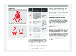 14
14 15
15 16
16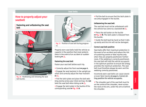 17
17 18
18 19
19 20
20 21
21 22
22 23
23 24
24 25
25 26
26 27
27 28
28 29
29 30
30 31
31 32
32 33
33 34
34 35
35 36
36 37
37 38
38 39
39 40
40 41
41 42
42 43
43 44
44 45
45 46
46 47
47 48
48 49
49 50
50 51
51 52
52 53
53 54
54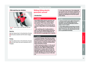 55
55 56
56 57
57 58
58 59
59 60
60 61
61 62
62 63
63 64
64 65
65 66
66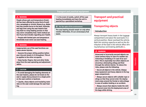 67
67 68
68 69
69 70
70 71
71 72
72 73
73 74
74 75
75 76
76 77
77 78
78 79
79 80
80 81
81 82
82 83
83 84
84 85
85 86
86 87
87 88
88 89
89 90
90 91
91 92
92 93
93 94
94 95
95 96
96 97
97 98
98 99
99 100
100 101
101 102
102 103
103 104
104 105
105 106
106 107
107 108
108 109
109 110
110 111
111 112
112 113
113 114
114 115
115 116
116 117
117 118
118 119
119 120
120 121
121 122
122 123
123 124
124 125
125 126
126 127
127 128
128 129
129 130
130 131
131 132
132 133
133 134
134 135
135 136
136 137
137 138
138 139
139 140
140 141
141 142
142 143
143 144
144 145
145 146
146 147
147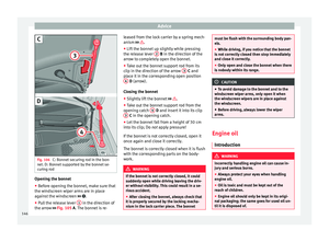 148
148 149
149 150
150 151
151 152
152 153
153 154
154 155
155 156
156 157
157 158
158 159
159 160
160 161
161 162
162 163
163 164
164 165
165 166
166 167
167 168
168 169
169 170
170 171
171 172
172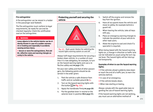 173
173 174
174 175
175 176
176 177
177 178
178 179
179 180
180 181
181 182
182 183
183 184
184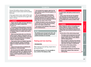 185
185 186
186 187
187 188
188 189
189 190
190 191
191 192
192 193
193 194
194 195
195 196
196 197
197 198
198 199
199 200
200 201
201 202
202 203
203 204
204 205
205 206
206 207
207 208
208 209
209 210
210 211
211 212
212 213
213 214
214 215
215 216
216 217
217 218
218
