Page 169 of 219
Wheels and tyres
Tyre code Fig. 119
Universal code on tyres Radial
Rim diameter code
Load index & speed rating
DOT tyre identification number
Severe snow conditions
Tyre ply composition and materials used
Max. load rating
Treadwear, traction and temperature
grades
Max. permissible inflation pressure
Passenger car tyre
Nominal width of tyre in millimetres
Ratio of height to width (aspect ratio)
1 2
3
4
5
6
7
8
9
10
11
12Tyre code (example)Meaning
Make, logotypeManufacturer
Product nameName of tyre assigned by manufacturer.
P255 / 55 R 18Size:
PPassenger vehicle code.
255Nominal width between walls, in mm.
55Height/width ratio in %
RTyre type (R indicates "radial").
18Rim diameter in inches»
167
Technical specifications
Advice
Operation
Safety
Page 170 of 219
Meaning
109 HLoad index
››› page 169 and speed rating ››› page 169.
XLReinforced tyres (“Reinforced”).
M+S or M/S or Winter tyres code (mud and snow tyr")
AdviceTyre code (example)Meaning
109 HLoad index
››› page 169 and speed rating ››› page 169.
XLReinforced tyres (“Reinforced”).
M+S or M/S or Winter tyres code (mud and snow tyres).
RADIAL TUBELESSRadial tyre without inner tube.
E4 ...E-mark certifying tyre complies with international legislation followed by a number denoting the country granting the au-
thorisation. The authorisation number ( several digits) is shown below.
DOT BT RA TY5 1709Tyre identification number (TIN a)
, may be only on interior wall of wheel) and date of manufacture:
DOTThe tyre complies with the legal requirements of the US Department of Transport, responsible for tyre
safety regulations.
BTPlace of manufacture code.
RAInformation about manufacturer and tyre size.
TY5Manufacturer's tyre specifications.
1709Date of manufacture: Week 17 of 2009.
TWIThis identifies the position of the Tread Wear Indicator ››› page 163.
Made in GermanyCountry of manufacture.
MAX LOAD 615 KGUS load rating, indicating maximum permitted load per tyre.
MAX INFLATION 350 KPA (51 PSI)US limit, indicating maximum permitted tyre pressure.
SIDEWALL 1 PLY RAYONInformation about tyre wall components:
1 layer of rayon (artificial silk).
TREAD 4 PLIES
1 RAYON + 2 STEEL + 1 NYLONInformation about tread components:
In the example, there are 4 layers below the tread: 1 layer of rayon (artificial silk), 2 layers of steel reinforcement and 1
layer of nylon.
Information for the end consumer concerning the comparative values of the established base tyres (standardised test procedures) ››› page 134: 168
Page 171 of 219
Meaning
TREADWEAR 220Relative service life of the tyre, with respect to specific US standard test.
TRACTION ABraking capacity of tyre on wet surface (AA, A, B or C).")
Wheels and tyresTyre code (example)Meaning
TREADWEAR 220Relative service life of the tyre, with respect to specific US standard test.
TRACTION ABraking capacity of tyre on wet surface (AA, A, B or C).
TEMPERATURE ATyre temperature resistance at higher test speeds (A, B or C).
If the tyre has other markings, these are specific tyre manufacturer codes or specific national codes, e.g. for Brazil or China.
a)
The letters TIN refer to the tyre serial number.
Tyres with directional tread pattern
Tyres with directional tread pattern have
been designed to operate best when rotating
in only one direction. An arrow on the tyre
sidewall indicates the direction of rotation on
tyres with directional tread. Always observe
the direction of rotation indicated when
mounting the wheel. This guarantees opti-
mum grip and helps to avoid aquaplaning,
grip, noise and wear.
If the tyre is mounted in the opposite direc-
tion of rotation, drive with extreme caution,
as the tyre is no longer being used correctly.
This is of particular importance when the
road surface is wet. Change the tyre as soon
as possible or remount it with the correct di-
rection of rotation.
Tyre load rating
The load rating code indicates the maximum
load in kilogrammes each wheel can carry
(load capacity). 425 kg
462 kg
487 kg
515 kg
545 kg
615 kg
Speed rating
The speed rating indicates the maximum
speed permitted for the tyres. max. 150 km/h (93 mph)
max. 160 km/h (99 mph)
max. 170 km/h (106 mph)
max. 180 km/h (112 mph)
max. 190 km/h (118 mph)
max. 200 km/h (124 mph)
max. 210 km/h (130 mph)
max. 240 km/h (149 mph)
max. 240 km/h (149 mph)
78
81
83
85
87
91
P
Q
R
S
T
U
H
V
Z max. 270 km/h (168 mph)
max. 300 km/h (186 mph)
Some manufacturers use the letters “ZR” for
tyres with a maximum authorised speed
above 240 km/h.
Snow chains When using snow chains, applicable local
legislation and maximum permitted speed
limits must be observed.
In winter weather, snow chains not only help
to improve grip but also improve the braking
capacity.
The fitting of chains is permitted
only on
front wheels and with the following combi-
nation
s of wheel trims and tyres :
»
W
Y
169
Technical specifications
Advice
Operation
Safety
Page 172 of 219

AdviceTyre sizeWheel rim
165/70 R145 J x 14 offset of 35175/65 R14
SEAT recommends you ask a technical serv-
ice for further information on wheel, tyre and
chain sizes.
Wherever possible use fine-link chains meas-
uring less than 15 mm including the lock.
Remove wheel hub covers and trim rings be-
fore fitting snow chains
››› . The wheel bolts
should be covered with caps for safety rea-
sons. These are available from technical serv-
ices.
Temporary spare wheel
For technical reasons, snow chains must not
be used on the compact temporary spare
wheel ›››
page 165.
If it is necessary to fit chains with the tempo-
rary spare wheel in use, install the wheel on
the rear axle in the event of a fault in a front
wheel. Then, fit the rear wheel that is free, in-
stead of the damaged front wheel. In this sit-
uation, observe the rotating direction of the
wheels. SEAT recommends attaching the
snow chains before fitting the wheel. WARNING
The use of unsuitable or incorrectly fitted
chains could lead to serious accidents and
damage.
● Always the appropriate snow chains.
● Observe the fitting instructions provided by
the snow chain manufacturer.
● Never exceed the maximum permitted
speeds when driving with snow chains. CAUTION
● Remove the snow chains to drive on roads
without snow. Otherwise they will impair ve-
hicle handling, damage the tyres and wear
out very quickly.
● Wheel rims may be damaged or scratched if
the chains come into direct contact with
them. SEAT recommends the use of covered
snow chains. Note
Snow chains are available in different sizes
according to the vehicle type. Emergencies
In case of emergency First aid kit, warning triangle and fire
extinguishers* Fig. 120
In the luggage compartment: stor-
age compartment for the warning triangle Warning triangle
In some vehicle equipment it is possible to
store the warning triangle model shown in a
storage compartment of the luggage com-
partment
››› Fig. 120 .
Fir s
t-aid kit
The first aid kit must comply with legal re-
quirements. Check the expiry date of the con-
tents of the first aid kit.
170
Page 173 of 219

Emergencies
Fire extinguisher
A fire extinguisher can be stored in a holder
in the passenger seat footwell.
The fire extinguisher must conform to legal
requirements, be ready for use and be
checked regularly. Check the certification
seal on the extinguisher. WARNING
Loose objects in the vehicle interior can be vi-
olently thrown in case of a sudden manoeu-
vre or braking and especially in accidents
causing serious injury.
● Secure or store fire extinguishers, first aid
kit, reflective vests and warning triangle se-
curely in the vehicle. Protecting yourself and securing the
vehicle
Fig. 121
Dash panel: Button for switching the
hazard lights warning system on and off. Always fulfil legal requirements for securing a
broken down vehicle. In a number of coun-
tries it is now obligatory, for example, to turn
on the hazard warning lights and use a re-
flective safety vest
››› page 170.
For your own safety and that of other passen-
gers, the following points should be ob-
served in the order given:
Park the vehicle a safe distance from
traffic and on suitable ground ››› .
Turn on the hazard warning lights with
the button
››› Fig. 121.
Apply the handbrake firmly ››› page 89.
Put the gearbox lever in neutral or the
selector lever in position N ››› page 93.
1.
2.
3.
4. Switch off the engine and remove the
key from the ignition.
Have all occupants leave the vehicle and
move to safety, for example behind a
guard rail.
When leaving the vehicle, take all keys
with you.
Place an emergency warning triangle to
indicate the position of your vehicle to
other road users.
Allow the engine to cool and check if a
specialist is required.
When being towed with the hazard warning
lights on, a change in direction or traffic lane
can be indicated as usual using the turn sig-
nal lever. The hazard lights will be interrup-
ted temporarily.
Examples of when to use the hazard warning
lights:
● If the vehicles ahead suddenly slow down
or reach the end of a traffic jam, to warn the
vehicles behind.
● In case of an emergency.
● If the vehicle breaks down.
● When tow-starting or towing.
Always comply with the applicable laws re-
garding the use of hazard warning lights.
If the hazard warning lights are not working,
you must use an alternative method of »
5.
6.
7.
8.
9.
171Technical specifications
Advice
Operation
Safety
Page 174 of 219

Advice
drawing attention to your vehicle. This meth-
od must comply with traffic legislation. WARNING
A faulty vehicle in traffic represents a risk of
accident for the driver and for other road
users.
● Stop the vehicle safely as soon as possible.
Park the vehicle a safe distance from sur-
rounding traffic to lock all the doors in case of
an emergency. Turn on the hazard warning
lights to warn other road users.
● Never leave children or disabled people
alone in the vehicle if the doors are to be
locked. In case of an emergency, passengers
will be trapped inside the vehicle. Individuals
locked in the vehicle can be exposed to very
high or very low temperatures. WARNING
The components of the exhaust system reach
very high temperatures. This could cause a
fire and considerable damage.
● Always park your vehicle so that no part of
the exhaust system can come in contact with
flammable materials (such as dried grass or
fuel). Note
● The vehicle battery will discharge and run
down if the hazard warning lights remain on
for too long (even with the ignition turned
off). ●
For some vehicles, the brake lights will
blink when braking suddenly at speeds of ap-
proximately 80 km/h (50 mph) to alert vehi-
cles to the rear. If braking continues, the haz-
ard warning lights system will automatically
be turned on at a speed of less than approxi-
mately 10 km/h (6 mph). The brake lights re-
main lit. Upon accelerating, the hazard warn-
ing lights will be automatically turned off. Vehicle tool kit*
Introduction When securing the vehicle in case of a break-
down, please note the legal requirements for
each country.
Vehicle tool kit
For vehicles with a factory-fitted spare wheel
or temporary spare wheel, in addition to win-
ter wheels, the luggage compartment may
contain additional vehicle tools
››› page 172. WARNING
When the vehicle tool kit, tire mobility set
and spare wheel are loose in the interior they
can be violently thrown in case of a sudden
manoeuvre or braking and especially in acci-
dents, causing serious injury.
● Ensure that the vehicle tool kit, the tire mo-
bility set and the spare wheel or temporary spare wheel are safely secured in the luggage
compartment.
WARNING
Unsuitable or damaged vehicle tools can
cause injury or accidents.
● Never work with inappropriate or damaged
tools. Location
Fig. 122
In the luggage compartment: Raised
carpet. The vehicle tool kit, spare wheel, temporary
spare wheel and the tire mobility set are stor-
ed in the luggage compartment under the
carpeted floor panel
›››
Fig. 122 .
● If nec
essary, remove the boot variable floor
››› page 73.
172
Page 175 of 219

››› Fig. 122 . Note
After use, return the jack to its initial position
using the handle in order to securely store it
in the vehicle. Acce")
Emergencies
● Raise the carpet at the recess (arrow)
››› Fig. 122 . Note
After use, return the jack to its initial position
using the handle in order to securely store it
in the vehicle. Accessing the vehicle tool kit and tyre
mobility system in vehicles fitted with
the SEAT SOUND 7 speaker system
(with subwoofer)*
●
Open the boot hatch and lift the shelf.
● If necessary, remove the boot variable floor
››› page 76 .
● Lif t
up the carpet from the recess and re-
move it from the luggage compartment.
● Disconnect the subwoofer’s speaker cable.
● Completely remove the hand-controlled
wheel from the centre of the subwoofer
speaker by turning it anti-clockwise.
● Take out the subwoofer, which is on top of
the tools and tyre mobility system.
● When finished, place the tools and system
back in the same way and place as before to
ensure the speaker sits properly in its hous-
ing. ●
Place the subwoofer in the direction of the
arrow and with the word “FRONT” facing for-
ward.
● Reconnect the speaker cable and firmly ro-
tate the securing wheel clockwise so that the
subwoofer is firmly in place.
Components Fig. 123
Components of the vehicle tool kit The vehicle tool kit depends on the vehicle
equipment. The following is a description for
a vehicle with all options.
The individual elements of the vehicle tool
kit
›
›› Fig. 123
Sc
rewdriver with hexagon socket in the
handle for screwing and unscrewing the
wheel bolts. The screwdriver bit is inter-
1 changeable. The screwdriver may be
found underneath the wheel spanner.
Adapter for anti-theft bolt. SEAT recom-
mend you carry the wheel bolt adapter in
the vehicle tool kit at all times. The
code
number of the anti-theft wheel bolt is
s t
amped on the front of the adapter. In
case it is lost, another adapter can be or-
dered using this number. Note the anti-
theft bolt code for the wheels and keep it
in a place other than the vehicle.
Towline anchorage, removable.
Wire hook for pulling off the wheel cover,
integral hubcaps and the wheel bolt
caps.
Jack. Before storing the jack in the tool
kit, fold its hook. The crank must then be
folded tight against the side of the jack in
order for it to be safely stored.
Wheel spanner.
Wheel bolt cap clips. Note
The jack does not generally require any main-
tenance. If required, it should be greased us-
ing universal type grease. 2
3
4
5
6
7
173
Technical specifications
Advice
Operation
Safety
Page 176 of 219

Advice
Changing a wheel Introduction Some vehicle versions and models do not
have a factory-fitted jack or box spanner. In
this case, we recommend consulting a Speci-
alised workshop to change the wheel.
You should only change the wheels yourself if
the vehicle is parked in a safe place, you are
familiar with the procedure and safety stand-
ards and you have all the necessary tools!
Otherwise, you should seek professional as-
sistance.
WARNING
Changing a wheel can be dangerous, espe-
cially on the hard shoulder. Please observe
the following rules to minimise the risk of in-
jury:
● Stop the vehicle safely as soon as possible.
Park at a safe distance from surrounding traf-
fic to change a wheel.
● When changing a wheel, keep all passen-
gers, and particularly children, a safe dis-
tance away from the work area.
● Turn on the hazard warning lights to warn
other road users.
● Ensure the ground on which you park is flat
and solid. If necessary, support the jack on a
wide solid base. ●
If you are changing a wheel yourself, you
should be familiar with the required proce-
dure. Otherwise, you should seek professio-
nal assistance.
● Only use suitable tools that are not dam-
aged when changing a wheel.
● Always stop the engine, apply the hand-
brake lever firmly and place the selector lever
in position P, or engage a gear for a manual
gearbox to reduce the risk of the vehicle mov-
ing accidentally.
● Have the tightening torque of the wheel
bolts checked as soon as possible with a reli-
able torque wrench. WARNING
If the wheel trims are not appropriate or not
fitted correctly, they could cause major acci-
dents or damage.
● Incorrectly mounted wheel trims may come
off while driving and endanger other road
users.
● Damaged trims must never be mounted on
the wheels.
● Always ensure that the brake ventilation
and cooling is not cut off or blocked. This is
also valid if hubcaps are fitted later. If there
is not enough air, you may require signifi-
cantly longer braking distances. CAUTION
Remove and remount wheel trims taking care
to avoid damage to the vehicle. Hubcaps
Fig. 124
Remove the hubcap of the steel
wheel trim In order to access the wheel bolts, first re-
move the hubcap.
Removing and fitting the hubcap
● To remove , take the vehicle tool kit wire
hook and att
ach it to the edge of the wheel
trim ››› Fig. 124
.
● Remove the trim by pulling it in the direc-
tion of the arrow.
● To replace the hubcap , press the hubcap
against the trim until it clicks into place.
174
 1
1 2
2 3
3 4
4 5
5 6
6 7
7 8
8 9
9 10
10 11
11 12
12 13
13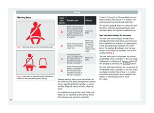 14
14 15
15 16
16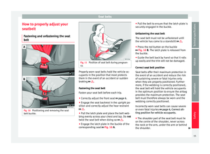 17
17 18
18 19
19 20
20 21
21 22
22 23
23 24
24 25
25 26
26 27
27 28
28 29
29 30
30 31
31 32
32 33
33 34
34 35
35 36
36 37
37 38
38 39
39 40
40 41
41 42
42 43
43 44
44 45
45 46
46 47
47 48
48 49
49 50
50 51
51 52
52 53
53 54
54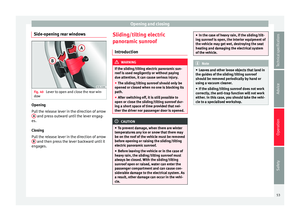 55
55 56
56 57
57 58
58 59
59 60
60 61
61 62
62 63
63 64
64 65
65 66
66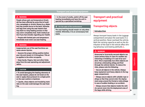 67
67 68
68 69
69 70
70 71
71 72
72 73
73 74
74 75
75 76
76 77
77 78
78 79
79 80
80 81
81 82
82 83
83 84
84 85
85 86
86 87
87 88
88 89
89 90
90 91
91 92
92 93
93 94
94 95
95 96
96 97
97 98
98 99
99 100
100 101
101 102
102 103
103 104
104 105
105 106
106 107
107 108
108 109
109 110
110 111
111 112
112 113
113 114
114 115
115 116
116 117
117 118
118 119
119 120
120 121
121 122
122 123
123 124
124 125
125 126
126 127
127 128
128 129
129 130
130 131
131 132
132 133
133 134
134 135
135 136
136 137
137 138
138 139
139 140
140 141
141 142
142 143
143 144
144 145
145 146
146 147
147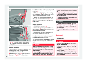 148
148 149
149 150
150 151
151 152
152 153
153 154
154 155
155 156
156 157
157 158
158 159
159 160
160 161
161 162
162 163
163 164
164 165
165 166
166 167
167 168
168 169
169 170
170 171
171 172
172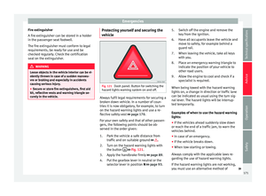 173
173 174
174 175
175 176
176 177
177 178
178 179
179 180
180 181
181 182
182 183
183 184
184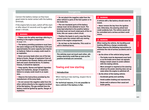 185
185 186
186 187
187 188
188 189
189 190
190 191
191 192
192 193
193 194
194 195
195 196
196 197
197 198
198 199
199 200
200 201
201 202
202 203
203 204
204 205
205 206
206 207
207 208
208 209
209 210
210 211
211 212
212 213
213 214
214 215
215 216
216 217
217 218
218