Page 177 of 219

Emergencies
The caps protect the wheel bolts and should
be remounted after changing the tyre.
Full hubcaps Fig. 125
Removing the full hubcap Removing the full hubcap
● Take the wheel brace and the wire hook
from the vehicle tool kit ››› page 172.
● Hook the wire through one of the grooves
on the hubcap.
● Insert the wheel brace onto the wire hook
››› Fig. 125 and pull the hub cap in the direc-
tion sho wn b
y the arrow.
Fitting hubcaps
Press the hubcap against the wheel so that
the space for the valve fits over the tyre valve.
Make sure that the hubcap is correctly fitted
all the way around the wheel. If you are using an anti-theft wheel lock, screw it in the oppo-
site position to the valve.
Wheel bolt caps Fig. 126
Removing the wheel bolt caps Removal
– Fit the plastic clip (vehicle tools
››› page 172 ) over the cap until it clicks into
p l
ace ››› Fig. 126.
– Remove the cap with the plastic clip.
The caps protect the wheel bolts and should
be remounted after changing the tyre.
The anti-theft wheel locking bolt ha
s a spe-
cial cap. This only fits on anti-theft locking
bolts and is not for use with standard wheel
bolts. Wheel bolts
Fig. 127
Changing a wheel: Slacken the
wheel bolts. Fig. 128
Changing a wheel: Tyre valve 1 and
position of anti-theft wheel locking bolt 2 .
Only use the tool supplied with the vehicle to
loosen the wheel bolts.
Loosen the wheel bolts only about one turn
before raising the vehicle with the jack.
»
175
Technical specifications
Advice
Operation
Safety
Page 178 of 219

Advice
If the wheel bolt is very tight, you may be
able to loosen it by pushing down on the end
of the wheel brace carefully with your foot.
Hold on to the vehicle for support and take
care not to slip.
Loosening wheel bolts
● Fit the wheel brace as far as it will go over
the wheel bolt ››› Fig. 127 .
● Ho l
d the wheel brace at the end and rotate
the bolt approximately one turn anticlockwise
››
› .
Loosening anti-theft wheel bolts
For wheels with full hubcap, the anti-theft
wheel lock must be threaded into position
››› Fig. 128 2 before mounting the hubcap.
Otherwise it will not be possible to mount the
entire hubcap.
● Take the adapter for anti-theft wheel bolts
out of the vehicle tool kit.
● Insert the adapter onto the wheel bolt
››› Fig. 128 . Push it on as far as it will go.
● Fit the wheel
brace onto the adapter as far
as possible.
● Hold the wheel brace at the end and rotate
the bolt approximately one turn anticlockwise
››
› . Important information about wheel bolts
The wheel rims and bolts have been de-
signed to be fitted to factory options. If differ-
ent rims are fitted, the correct wheel bolts
with the right length and correctly shaped
bolt heads must be used. This ensures that
wheels are fitted securely and that the brake
system functions correctly.
In some circumstances, wheel bolts from the
same model vehicle should not be used.
Wheel bolt tightening torque
The prescribed tightening torque for wheel
bolts for steel and alloy wheels is
110 Nm
.
Hav e the tight
ening torque of the wheel bolts
checked as soon as possible with a reliable
torque wrench.
If wheel bolts are rusty and it is difficult to
tighten them, the threads should be replaced
and cleaned before checking the tightening
tor
que.
Never grease or lubricate wheel bolts or the
wheel hub threads. Although they have been
tightened to the prescribed torque, they
could come loose while driving. WARNING
If the wheel bolts are not fitted correctly they
could be released while driving leading to
loss of vehicle control and serious damage. ●
Only use wheel bolts which correspond to
the wheel rims in question.
● Never use different wheel bolts.
● The bolts and threads should be clean, free
of oil and grease and easy to thread.
● To loosen and tighten the wheel bolts, al-
ways use the wheel brace supplied with the
vehicle.
● Loosen the wheel bolts only about one turn
before raising the vehicle with the jack.
● Never grease or lubricate wheel bolts or the
wheel hub threads. Although they have been
tightened to the prescribed torque, they
could come loose while driving.
● Never loosen the bolted joints of wheel
rims with bolted ring trims.
● If the wheel bolts are not tightened to the
correct torque, they may come loose while
driving, and the bolts and rims may come
out. If the tightening torque is too high, the
wheel bolts and threads can be damaged. 176
Page 179 of 219

Emergencies
Raising the vehicle with the jack Fig. 129
Jack position points Fig. 130
Jack mounted on the left rear part of
the vehicle The jack may be applied only at the jacking
points shown (marks on chassis)
››› Fig. 129 .
A lw
ays the relevant jacking point for the
wheel to be changed ››› .
Raise the vehicle using only the designated
jacking points. WARNING
If the vehicle is not correctly raised, it could
fall off the jack causing serious injury. Please
observe the following rules to minimise the
risk of injury:
● You should only use a jack approved by
SEAT for your vehicle. Other jacks, even those
approved for other SEAT models, might slip
out of place.
● The ground should be firm and flat. If the
ground is sloped or soft then the vehicle
could slip and fall off the jack. If necessary,
support the jack on a wide solid base.
● If the ground is slippery, such as tiles,
place a non-slip surface (a floor mat, for in-
stance) beneath the jack to avoid slipping.
● Only fit the jack at the prescribed jacking
points. The claw of the jack should grip the
reinforcement nerve on the underbody
››› Fig. 130.
● You shou
ld never place a body limb such as
an arm or leg under a raised vehicle that is
solely supported by the jack.
● If you have to work underneath the vehicle,
you must use suitable stands additionally to
support the vehicle, there is a risk of acci-
dent!.
● Never raise the vehicle if it is tilting to one
side or the engine is running.
● Never start the engine when the vehicle is
raised. The vehicle may come loose from the
jack due to the engine vibrations. 177
Technical specifications
Advice
Operation
Safety
Page 180 of 219

Advice
Changing a wheel Fig. 131
Changing a wheel: loosen wheel
bolts with the socket at the end of the wheel
brace Removing the wheel
● Loosen the wheel bolts ››› page 175 .
● Jacking up the vehicle ››› page 177.
● Using the hexagonal socket in the wheel
brace ››› Fig. 131 , unscrew the slackened
wheel bo
lts and place them on a clean sur-
face.
● Take off the wheel.
How to use the spare wheel or temporary
spare wheel
Check the direction of rotation of the tyre
››› page 167, Tyre code.
● Plac
e the spare wheel or temporary spare
wheel into position. ●
Replace the wheel bolts and tighten slight-
ly using the hexagonal socket on the end of the wheel br
ace.
● To tighten the anti-theft locking wheel bolts
use the corresponding adaptor.
● Lower the car with the jack.
● Tighten all of the wheel bolts clockwise
››› . Tighten the bolts in diagonal pairs (not
in a circle).
● Put the caps, trim or full hubcap back on
››› page 174 . WARNING
If the wheel bolts are not treated suitably or
not tightened to the correct torque then this
could lead to loss of vehicle control and to a
serious accident.
● All the wheel bolts and hub threads should
be clean and free of oil and grease. The wheel
bolts should be easily tightened to the cor-
rect torque.
● The hexagonal socket in the wheel brace
should be used for turning wheel bolts only.
Do not use it to loosen or tighten the wheel
bolts. After changing the wheel
●
Clean the vehicle tools, if necessary and
put them away in the luggage compartment
foam holder ›››
page 172 . ●
St or
e the spare wheel, the temporary spare
wheel or the changed wheel securely in the
luggage compartment.
● Have the tightening torque of the wheel
bolts checked as soon as possible with a tor-
que wrench ››› page 176
.
● Have the flat tyre replaced as quickly as
possible.
Tyre repair
TMS (Tyre Mobility System)* The Anti-puncture kit* (Tyre Mobility System)
will reliably seal punctures caused by the
penetration of a foreign body of up to about
4 mm
in diameter.
Do not remove foreign ob-
j
ects, e.g. screws or nails, from the tyre.
After inserting the sealant residue in the tyre,
you must again check the tyre pressure about
10 minutes after starting the engine.
You should only use the tire mobility set if
the vehicle is parked in a safe place, you are
familiar with the procedure and you have the
necessary tire mobility set! Otherwise, you
should seek professional assistance.
The tyre sealant must not be used in the
following cases: ● If the wheel rim has been damaged.
178
Page 181 of 219
.
● In the event of cuts or perforations in the
tyre greater than 4 mm.
● If you have been driving with very low pres-
sure or a compl")
Emergencies
● In outside temperatures below -20 °C
(-4 °F).
● In the event of cuts or perforations in the
tyre greater than 4 mm.
● If you have been driving with very low pres-
sure or a completely flat tyre.
● If the sealant bottle has passed its use by
date. WARNING
Using the tyre mobility system can be dan-
gerous, especially when filling the tyre at the
roadside. Please observe the following rules
to minimise the risk of injury:
● Stop the vehicle safely as soon as possible.
Park it at a safe distance from surrounding
traffic to fill the tyre.
● Ensure the ground on which you park is flat
and solid.
● All passengers and particularly children
must keep a safe distance from the work area.
● Turn on the hazard warning lights to warn
other road users.
● Use the tyre mobility system only if you are
familiar with the necessary procedures. Oth-
erwise, you should seek professional assis-
tance.
● The tyre mobility set is intended for tempo-
rary emergency use only until you can reach
the nearest specialised workshop.
● Replace the repaired tyre with the tire mo-
bility set as soon as possible. ●
The sealant is a health hazard and must be
cleaned immediately if it comes into contact
with the skin.
● Always keep the tire mobility set out of the
reach of small children.
● Never use an equivalent jack, even if it has
been approved for your vehicle.
● Always stop the engine, apply the hand-
brake lever firmly and engage gear if using a
manual gearbox, in order to reduce the risk of
vehicle involuntary movement. WARNING
A tyre filled with sealant does not have the
same performance properties as a conven-
tional tyre.
● Never drive faster than 80 km/h (50 mph).
● Avoid heavy acceleration, hard braking and
fast cornering.
● Drive for only 10 minutes at a maximum
speed of 80 km/h (50 mph) and then check
the tyre. For the sake of the environment
Dispose of used or expired sealant observing
any legal requirements. Note
● A new bottle of sealant can be purchased at
SEAT dealerships. ●
Take into account the separate instruction
manual of the tyre mobility set* manufactur-
er. Contents of the tyre mobility system*
Fig. 132
Standard representation: Contents
of the tyre mobility system. The tyre mobility set is located underneath
the floor covering in the luggage compart-
ment. It includes the following components
››› Fig. 132 :
T y
re valve remover
Sticker indicating maximum speed “max.
80 km/h” or “max. 50 mph”
Filler tube with cap
Air compressor »
1 2
3
4
179
Technical specifications
Advice
Operation
Safety
Page 182 of 219

Air bleed screw 2)
ON/OFF switch
12 volt connector
Bottle of sealant
Spare tyre valve
The valve insert remover")
Advice
Tube for inflating tyres
Warning provided by tyre pressure moni-
toring system 1)
Air bleed screw 2)
ON/OFF switch
12 volt connector
Bottle of sealant
Spare tyre valve
The valve insert remover
1 has a gap at the
lower end for a valve insert. The valve insert
can only be screwed or unscrewed in this
way. This also applies to its replacement part 11 .
Sealing and inflating a tyre Sealing a tyre
● Unscrew the tyre valve cap.
● Use the corresponding enclosed extractor
››› Fig. 132 1 to unscrew the tyre valve in-
sert. Place the valve insert on a clean surface.
● Vigorously shake the sealant bottle
››› Fig. 132 10 for several seconds.
● Screw the inflator tube ›››
Fig. 132 3 se-
curely into the sealant bottle in a clockwise 5 6
7
8
9
10
11 direction. The seal on the mouth of the bottle
moves automatically.
●
Remove the lid from the filling tube
››› Fig. 132 3 and screw the open end of the
tube into the tyre valve.
● Hold the tyre sealant can upside down and
fill the complete contents of the can into the
ty r
e.
● Remove the tyre sealant bottle from the
valve.
● Screw the valve insert again with the corre-
sponding enclosed extractor ››› Fig. 132 1 into the tyre valve.
Inflating the tyre
●
Securely screw the tyre inflator tube
››› Fig. 132 5 of the compressor into the tyre
valve.
● Check whether the air bleed screw
››› Fig. 132 7 is closed.
● Start the vehicle engine and leave it run-
ning.
● Attach the connector ››› Fig. 132 9 to a 12
volt socket of the vehicle ››› page 72.
● Connect the air compressor with the
ON/OFF switch ››› Fig. 132 8 .●
Keep the air compressor running until it
reaches 2.0 to 2.5 bar (29-36 psi /
200-250 kPa) ››› .
Maximum operation time
8 minut e
s ››› .
● Disconnect the air compressor.
● If it is not possible to achieve an air pres-
sure of 2.0 to 2.5 bar (29-36 psi /
200-250 kPa), unscrew the tyre inflator tube
from the tyre valve.
● Move the vehicle some 10 metres forward
or backward so that the sealant is evenly dis-
tributed in the tyre interior.
● Securely screw the compressor tyre inflator
tube into the tyre valve and repeat the infla-
tion process.
● If the indicated pressure can still not be
reached, the tyre is too badly damaged. The
tyre cannot be sealed with the anti-puncture
kit. Do not continue driving. You should ob-
tain professional assistance ››› .
● Disconnect the air compressor and unscrew
the flexible inflator tube from the tyre valve.
● When the tyre pressure is between 2.5 and
2.0 bars, immediately continue driving with-
out exceeding 80 km/h (50 mph).
● After 10 minutes
, Check the pressure again
›
›› page 181. 1)
It can also be integrated in the compressor.
2) In its place, the compressor may have a button.
180
Page 183 of 219

Emergencies
WARNING
When inflating the wheel, the air compressor
and the inflator tube may become hot.
● Protect hands and skin from hot parts.
● Do not place the hot flexible inflator tube or
hot air compressor on flammable material.
● Allow them to cool before storing the de-
vice.
● If it is not possible to inflate the tyre to at
least 2.0 bars (29 psi / 200 kPa), the tyre is
too badly damaged. The sealant is not in a
good condition to seal the tyre. Do not con-
tinue driving. Seek specialist assistance. CAUTION
Switch off the air compressor after a maxi-
mum of 8 operational minutes to avoid over-
heating! Before switching on the air compres-
sor again, let it cool for several minutes. Check after 10 minutes of driving
Screw in the inflator tube
›››
Fig. 132 5 again and check the pressure on the gauge
6 .
1.3 bar (19 psi / 130 kPa) and lower:
● Stop the vehicle! The tyre cannot be sealed
sufficiently with the tyre mobility set.
● You should obtain professional assistance
››› . 1.4 bar (20 psi / 140 kPa) and higher:
●
Set the tyre pressure to the correct value
again ››› page 158 .
● Car
efully resume your journey until you
reach the nearest specialised workshop with-
out exceeding 80 km/h (50 mph).
● Have the damaged tyre replaced. WARNING
Driving with an unsealed tyre is dangerous
and can cause accidents and serious injury.
● Do not continue driving if the tyre pressure
is 1.3 bar (19 psi / 130 kPa) and lower.
● Seek specialist assistance. Starting assistance
Introduction If the engine fails to start because of a dis-
charged battery, the battery of another vehi-
cle can be used to start the engine. Before
starting, check the magic eye on the battery
››› page 154 .
F or s
tarting assistance, jump lead cables con-
forming to the standard DIN 72553 are re-
quired (see the cable manufacturer instruc-
tions). The cable section in vehicles with pet-
rol engine must be at least 25 mm 2
. WARNING
Incorrect use of jump leads and incorrectly
jump starting could cause the battery to ex-
plode resulting in serious injury. Please ob-
serve the following rules to minimise the risk
of a battery explosion:
● The battery providing current must have
the same voltage (12V) and approximately
the same capacity (see markings on battery)
as the flat battery.
● Never charge a frozen or recently thawed
battery. A flat battery can also freeze at tem-
peratures close to 0 °C (+32 °F).
● If a battery is frozen and/or has been frozen
then it must be replaced.
● A highly explosive mixture of gases is re-
leased when the battery is being charged. Al-
ways keep lit cigarettes, flames, sparks and
fire far from the battery. Never use a mobile
telephone when connecting and removing the
jump leads.
● Charge the battery only in well ventilated
areas given that when the battery is charged
by outside assistance, it creates a mix of
highly explosive gases.
● Jump leads should never enter into contact
with moving parts in the engine compart-
ment.
● Never switch the positive and negative
poles or connect the jump leads incorrectly.
● Note the instruction manual provided by
the manufacturer of the jump leads. » 181
Technical specifications
Advice
Operation
Safety
Page 184 of 219

Advice
CAUTION
To avoid considerable damage to the vehicle
electrical system, note the following careful-
ly: ● If the jump leads are incorrectly connected,
this could result in a short circuit.
● The vehicles must not touch each other,
otherwise electricity could flow as soon as
the positive terminals are connected. How to jump start: description
Fig. 133
Diagram of connections for vehicles
without Start-Stop system. Fig. 134
Diagram of connections for vehicles
with Start-Stop system. Jump lead terminal connections
1. Switch off the ignition of both vehicles
››› .
2. Connect one end of the red jump lead to
the po s
itive + terminal of the vehicle
with the flat battery A
››› Fig. 133 .
3. C
onnect the other end of the red
jump
lead to the positive terminal + in the ve-
hicle providing assistance B .
4. For vehicles without Start-Stop system:
connect one end of the black jump lead to
the negative terminal – of the vehicle
providing the current B
››› Fig. 133 .
– For
vehicles with Start-Stop system: con-
nect one end of the black jump lead X to a
suitable ground terminal, to a solid piece of
metal in the engine block, or to the engine
block itself ››› Fig. 134 . 5.
C
onnect the other end of the
black jump
lead X to a solid metal component bolted
to the engine block or to the engine block
itself of the vehicle with the flat battery.
Do not connect it to a point near the bat-
tery A .
6. Position the leads in such a way that they cannot come into contact with any moving
parts in the engine compartment.
Starting
7. Start the engine of the vehicle with the boosting battery and let it run at idling
speed.
8. Start the engine of the vehicle with the flat battery and wait 2 or 3 minutes until the
engine is “running”.
Removing the jump leads
9. Before you remove the jump leads, switch off the dipped beam headlights (if they
are switched on).
10. Turn on the heater blower and heated rear
w indo
w in the vehicle with the flat battery.
This helps minimise voltage peaks which
are generated when the leads are discon-
nected.
11.When the engine is running, disconnect the leads in reverse order to the details
given above.
182
 1
1 2
2 3
3 4
4 5
5 6
6 7
7 8
8 9
9 10
10 11
11 12
12 13
13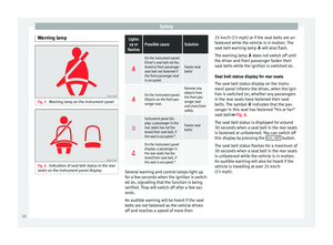 14
14 15
15 16
16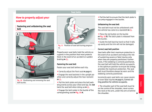 17
17 18
18 19
19 20
20 21
21 22
22 23
23 24
24 25
25 26
26 27
27 28
28 29
29 30
30 31
31 32
32 33
33 34
34 35
35 36
36 37
37 38
38 39
39 40
40 41
41 42
42 43
43 44
44 45
45 46
46 47
47 48
48 49
49 50
50 51
51 52
52 53
53 54
54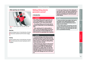 55
55 56
56 57
57 58
58 59
59 60
60 61
61 62
62 63
63 64
64 65
65 66
66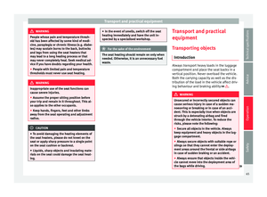 67
67 68
68 69
69 70
70 71
71 72
72 73
73 74
74 75
75 76
76 77
77 78
78 79
79 80
80 81
81 82
82 83
83 84
84 85
85 86
86 87
87 88
88 89
89 90
90 91
91 92
92 93
93 94
94 95
95 96
96 97
97 98
98 99
99 100
100 101
101 102
102 103
103 104
104 105
105 106
106 107
107 108
108 109
109 110
110 111
111 112
112 113
113 114
114 115
115 116
116 117
117 118
118 119
119 120
120 121
121 122
122 123
123 124
124 125
125 126
126 127
127 128
128 129
129 130
130 131
131 132
132 133
133 134
134 135
135 136
136 137
137 138
138 139
139 140
140 141
141 142
142 143
143 144
144 145
145 146
146 147
147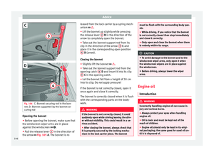 148
148 149
149 150
150 151
151 152
152 153
153 154
154 155
155 156
156 157
157 158
158 159
159 160
160 161
161 162
162 163
163 164
164 165
165 166
166 167
167 168
168 169
169 170
170 171
171 172
172 173
173 174
174 175
175 176
176 177
177 178
178 179
179 180
180 181
181 182
182 183
183 184
184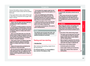 185
185 186
186 187
187 188
188 189
189 190
190 191
191 192
192 193
193 194
194 195
195 196
196 197
197 198
198 199
199 200
200 201
201 202
202 203
203 204
204 205
205 206
206 207
207 208
208 209
209 210
210 211
211 212
212 213
213 214
214 215
215 216
216 217
217 218
218