Page 41 of 219

Cockpit
Control lamps Control and warning lamps The control and warning lamps are indicators
of warnings,
››› , faults
››› or certain func-
tions. Some control and warning lamps come
on when the ignition is switched on, and
switch off when the engine starts running, or
while driving.
When certain control and warning lamps are
lit, an audible warning is also heard.SymbolMeaning ››› See
Handbrake applied.
›››
page
89 Do not continue driving!
The brake fluid level is too low
or there is a fault in the brake
system.
it lights up:
Do not continue
driving!
The liquid coolant level is too
low,
the engine liquid coolant tem-
perature is too high or
there is a fault in the liquid cool-
ant system.
››› page
150
flashes: engine coolant system
faulty.››› page
150
Do not continue driving!
Engine oil pressure too low.››› page
146
SymbolMeaning ››› See
lights up or flashes:
Do not
continue driving!
Fault in the steering.››› page
84
On the instrument panel: driver
or passenger has not fastened
seat belt.
›››
page
11
Instrument panel display: a pas-
senger in the rear seats has fas-
tened their seatbelt.
A passenger in the rear seats
has not fastened their seat belt.›››
page
11
Faulty generator.›››
page
154
Vehicles with the Start-Stop sys-
tem: it is necessary to start the
engine manually.››› page
115
flashes in addition to the rest of
the segments of the fuel gauge:
Fuel tank almost empty.›››
page
139
SymbolMeaning ››› See
flashes quickly:
the City Safety
Assist system function* brakes
automatically or has braked au-
tomatically. Or:
flashes slowly: City Safety Assist
function is not currently availa-
ble.
››› page
110
The City Safety Assist* function
has been connected manually. It
switches off after 5 seconds.
flashes: The City Safety Assist*
function has been manually dis-
connected.
after the ignition is switched on:
indication that the end of the
period for an inspection to be
performed is approaching.››› page
36
it lights up:
ESC* faulty or dis-
connected by the system. ALTER-
NATIVELY:
flashes: ESC* or ASR regulating.
››› page
89 it lights up:
Traction Control faul-
ty or switched off by the system.
ALTERNATIVELY:
flashes: Traction Control regula-
tor operating.
ABS faulty or does not work.
Rear fog light switched on.›››
page
55» 39
Technical specifications
Advice
Operation
Safety
Page 42 of 219

OperationSymbolMeaning
››› See
lights up or flashes:
fault in cata-
lytic converter.››› page
101
Fault in engine management.
lights up or flashes:
fault in the
steering system.››› page
84
Fuel tank almost empty.›››
page
139
Fault in airbag system and seat
belt tensioners.›››
page
17
it lights up:
the Start-Stop sys-
tem is enabled. ALTERNATIVELY:
flashes: the Start-Stop system is
not available.
››› page
115
The Start-Stop system is enabled
but the engine cannot be auto-
matically stopped.
Tyre pressure* too low›››
page
164
Left or right turn signal.›››
page
55
Hazard warning lights on.››› page
170
Cruise control operating.›››
page
107
Main beam on or flasher on.›››
page
55
The natural gas engine coolant
temperature is too low. WARNING
If the warning lamps are ignored, the vehicle
may stall in traffic, or may cause accidents
and severe injuries.
● Never ignore the warning lamps.
● Stop the vehicle safely as soon as possible.
● Park the vehicle away from traffic and en-
sure that there are no highly flammable ma-
terials under the vehicle that could come into
contact with the exhaust system (e.g. dry
grass, fuel).
● A faulty vehicle represents a risk of acci-
dent for the driver and for other road users. If
necessary, switch on the hazard warning
lamps and put out the warning triangle to ad-
vise other drivers.
● Before opening the bonnet, switch off the
engine and allow it to cool.
● In any vehicle, the engine compartment is a
hazardous area and could cause severe inju-
ries ››› page 143. CAUTION
Failure to heed the warning lamps when they
appear may result in faults in the vehicle. SEAT information system
Introduction With the ignition switched on it is possible to
access different messages via the display on
the instrument panel display.
The number of messages displayed on the in-
strument panel display will vary according to
the vehicle electronics and equipment.
A specialised workshop will be able to pro-
gramme or modify additional functions, ac-
cording to the vehicle equipment. SEAT rec-
ommends taking your car in for technical
service.
WARNING
Any distraction may lead to an accident, with
the risk of injury.
● Do not consult the messages on the instru-
ment panel screen when driving. Note
On the screen of the SEAT Portable System
(supplied by SEAT) ››› page 123 other func-
tion s
of the vehicle can be seen. 40
Page 43 of 219

Cockpit
Control functions of the instrument
panel display Fig. 26
Windscreen wiper lever: control but-
tons. Calling up options
● Switch the ignition on.
● If a message or vehicle symbol is dis-
played, press OK/RESET (
››› Fig. 26 A ).
● Press the top or bottom part of the rocker
switch ››› Fig. 26 B until the desired option
appears.
Multifunction display (MFI) The multifunction display (MFI) has two auto-
matic memories:
1 - Partial memory and 2 -
Total memory . The selected memory will be
shown in the lower right-hand corner of the
display.With the ignition switched on, and memory 1 or
2 displayed, briefly press OK to change from
one memory to another.
1
Trip memo-
ry (for a
single jour-
ney).
The memory stores the values for the
journey and the consumption from
the moment the ignition is switched
on until it is switched off again.
If the journey is broken for more than
2 hours, the memory is automatically
erased. If the journey is continued in
less than 2 hours after the ignition is
switched off, the new data is added to
the data already stored in the memo-
ry.
2Total mem-
ory (for all
journeys).
The memory stores the values of any
number of journeys, until it counts a
total of 19 hours and 59 minutes of
driving, or 1999.9 km or miles of driv-
ing, depending on the type of instru-
ment panel fitted. On reaching either
of these limits, the memory is auto-
matically erased and starts to count
from 0 again. Possible displays
MenuFunction
TimeCurrent time in hours (h) and minutes
(min).
Journey dura-
tionThis indicates the hours (h) and mi-
nutes (min) since the ignition was
switched on.
MenuFunction
Current fuel
consumptionThe current fuel consumption display
operates throughout the journey, in
l/100 km; with the engine running
and the vehicle stopped, in l/hour.
Average fuel
consumptionAfter turning on the ignition, average
fuel consumption in litres/100 km will
be displayed after travelling about
100 metres. Otherwise horizontal
lines are displayed. The value shown
is updated approximately every 5 sec-
onds.
Operating
rangeApproximate distance in km that can
still be travelled with the fuel remain-
ing in the tank, assuming the same
style of driving is maintained. This is
calculated using the current fuel con-
sumption.
Distance cov-
eredDistance travelled, after ignition is
switched on, in km.
Average speedThe average speed will be shown after
a distance of about 100 metres has
been travelled. Otherwise horizontal
lines are displayed. The value shown
is updated approximately every 5 sec-
onds.
Digital display
of speedCurrent speed displayed digitally.
Liquid coolant
temperature
digital displayDigital display of the current tempera-
ture of the engine liquid coolant.»
41
Technical specifications
Advice
Operation
Safety
Page 44 of 219
, an audible warning is giv-
en together with a visual warning.
Changing between disp")
OperationMenuFunction
Warning at ---
km/hIf the stored speed is exceeded (be-
tween 30 - 250 km/h, or 18 -
155 mph), an audible warning is giv-
en together with a visual warning.
Changing between display modes
● Press the rocker switch in the windscreen
wiper lever.
Storing a speed for the speed warning
● Select the display Speed warning at --- km/h
.
● Press OK on the windscreen wiper lever to
store the current speed and switch off the
warning.
● In addition, set the required speed by
pressing the rocker switch on the windscreen
wiper lever or or
buttons on the multi-
function steering wheel for 5 seconds. Next,
press OK again or wait a few seconds. The
speed is stored and the warning activated.
● To switch off , press OK . The stored speed is
deleted.
Manually erasing memory 1 or 2
● Select the memory to be erased.
● Press and hold the eject button OK for ap-
proximately 2 seconds. Note
On the screen of the SEAT Portable System
(supplied by SEAT) ››› page 123 other func-
tion s
of the multifunction display can be
seen. 42
Page 45 of 219

Opening and closing
Opening and closing Vehicle key set Remote control vehicle key* Fig. 27
Remote control key Remote control key
With the vehicle key the vehicle may be
locked or unlocked remotely
››› page 45.
The vehicle key includes an emitter and bat-
tery. The receiver is in the interior of the vehi-
cle. The range of the vehicle key with remote
control and new battery is several metres
around the vehicle.
If it is not possible to open or close the vehi-
cle using the remote control key, this should
be re-synchronised ››› page 45 or the bat-
tery changed ››› page 44. Different keys belonging to the vehicle may
be used.
Folding the key shaft in and out
When the button is pressed
››› Fig. 27 A , the
key shaft is released and unfolds.
To fold it
press the button and fold the key
sh
aft in until it locks in place.
Replacing a key
To obtain a spare key and other vehicle keys,
the vehicle chassis number is required.
Each new key must contain a microchip and
be coded with the data from the vehicle elec-
tronic immobiliser. A vehicle key will not work
if it does not contain a microchip or the mi-
crochip has not been encoded. This is also
true for keys cut for the vehicle.
The vehicle keys or new spare keys can be
obtained from a SEAT dealership, a Special-
ised workshop or approved key service quali-
fied to create this kind of key.
New keys or spare keys must be synchron-
ised before use ››› page 45. WARNING
Careless or incorrect use of vehicle keys may
result in severe injury and accident.
● Always take all the keys with you whenever
you leave the vehicle. Children and unauthor-
ised individuals could lock the doors or the boot hatch, start the engine or turn on the ig-
nition, activating electrical systems, the elec-
tric windows, for example.
●
Never leave children or disabled people
alone in the car. They could be trapped in the
car in an emergency and will not be able to
get themselves to safety. For example, de-
pending on the time of the year, tempera-
tures inside a locked and closed vehicle can
be extremely high or extremely low resulting
in serious injuries and illness or even death,
particularly for young children.
● Never remove the key from the ignition if
the vehicle is in motion. The steering may
lock and it will not be possible to turn the
steering wheel. CAUTION
The remote control key contains electronic
components. Protect them from damage, im-
pacts and humidity. Note
● Only use the key button when you require
the corresponding function. Pushing the but-
ton unnecessarily could accidentally unlock
the vehicle or trigger the alarm. It is also pos-
sible even when you are outside the radius of
action.
● Remote control key operation can be great-
ly influenced by overlapping radio signals
around the vehicle working in the same range » 43Technical specifications
Advice
Operation
Safety
Page 46 of 219
.
● Obstacles between the remote control and
the vehicle, bad weather conditions and
draining batteries can considerably")
Operation
of frequencies (for example, radio
transmitters, mobile telephones).
● Obstacles between the remote control and
the vehicle, bad weather conditions and
draining batteries can considerably reduce
the range of the remote control.
● If the buttons of the vehicle key are press-
ed ››› Fig. 27 or one of the central locking but-
t on
s ››› page 45 is pressed repeatedly in
quick
succession, the central locking briefly
disconnects as protection against overload-
ing. The vehicle is then unlocked. Lock it if necessary. Vehicle mechanical key
Fig. 28
Vehicle mechanical key The vehicle key set may include a mechanical
key
››› Fig. 28 . D
up
licate keys
To obtain a spare key and other vehicle keys,
the vehicle chassis number is required.
Each new key must contain a microchip and
be coded with the data from the vehicle elec-
tronic immobiliser. A vehicle key will not work
if it does not contain a microchip or the mi-
crochip has not been encoded. This is also
true for keys cut for the vehicle.
The vehicle keys or new spare keys can be
obtained from a SEAT dealership, a special-
ised workshop or an approved locksmith
qualified to create them.
Control lamp on the vehicle key Fig. 29
Control lamp on the vehicle key When a button on the vehicle key is pressed,
the control lamp flashes
››› Fig. 29 (arrow)
onc e briefly
. If the button is pressed and
held, the indicator blinks several times, for example: for the convenience opening func-
tion.
When the control lamp does not light upon
pushing a button, the vehicle key batteries
must be changed
››› page 44.
Changing the battery Fig. 30
Vehicle key: battery compartment cov-
er Fig. 31
Vehicle key: removing the battery44
Page 47 of 219

Opening and closing
SEAT recommend having the batteries
changed in a specialised workshop.
The battery is located to the rear of the vehi-
cle key, under a cover.
Changing the battery
● Unfold the vehicle key shaft ››› page 43.
● Remove the cover from the back of the ve-
hicle key ››› Fig. 30 in the direction of the ar-
r o
w ››› .
● Extract the battery from the compartment
using a suitable thin object ››› Fig. 31 .
● Plac
e the new battery in the compartment,
pressing in the direction of the arrow as
shown ››› Fig. 31 ››› .
● Fit the battery compartment cover, pressing
in the direction of the arrow as shown
››› Fig. 30 until it clicks into place. CAUTION
● If the battery is not changed correctly, the
vehicle key may be damaged.
● Use of unsuitable batteries may damage
the vehicle key. For this reason, always re-
place the dead battery with another of the
same voltage, size and specifications.
● When fitting the battery, check that the po-
larity is correct. For the sake of the environment
Please dispose of your used batteries correct-
ly and with respect for the environment. Synchronising the vehicle key
If the button
is pressed frequently outside
of the vehicle range, it is possible that the ve-
hicle can no longer be locked or unlocked us-
ing the key. In this case, the vehicle key must
be synchronised once more as follows:
● Unfold the vehicle key shaft ›››
page 43.
● Press the button on the vehicle key. For
this, it must remain with the vehicle.
● Open the vehicle within one minute using
the key shaft.
● Turn on the ignition using the vehicle key.
The key has been synchronised.
● If necessary, fit the cap.
Central locking* and locking
system Introduction Central locking functions correctly when all
the doors and the rear lid are correctly shut.If the driver door is open, the vehicle
cannot
be locked with the key.
The battery of an unlocked vehicle parked for
a long period (e.g. in a private garage) may
run down and fail to start the motor. WARNING
The incorrect use of the central locking sys-
tem may cause serious injuries.
● The central locking system will lock all
doors. A vehicle locked from the inside can
prevent any non-authorised individual from
opening the doors and accessing the vehicle.
Nevertheless, in case of emergency or acci-
dent, locked doors will complicate access to
the vehicle interior to help the passengers.
● Never leave children or disabled people
alone in the vehicle. The central locking but-
ton can be used to lock all the doors from
within. Therefore, passengers will be locked
inside the vehicle. Individuals locked in the
vehicle can be exposed to very high or very
low temperatures.
● Depending on the time of the year, temper-
atures inside a locked and closed vehicle can
be extremely high or extremely low resulting
in serious injuries and illness or even death,
particularly for young children.
● Never leave individuals locked in a closed
and locked vehicle. In case of emergency,
they may not be able to exit the vehicle by
themselves or get help. 45
Technical specifications
Advice
Operation
Safety
Page 48 of 219

Operation
Description of the central locking
system The central locking system allows all doors
and the rear lid to be locked and unlocked
centrally.
● From outside, using the vehicle key.
● From inside, by pushing the central locking
button ››› page 48.
The c entr
al locking system can be activated
or deactivated at a specialised workshop.
In case of a vehicle key fault or central lock-
ing system fault, all doors can be locked or
unlocked manually.
Locking the vehicle after the airbags have
been deployed
If the airbags are deployed due to an acci-
dent, the vehicle will be automatically and
completely unlocked. Depending on the
amount of damage, it can be locked follow-
ing an accident in the following ways:
FunctionNecessary operations
Lock the vehicle,
by pushing the
central locking
button:– Turn off the ignition and turn it on
again.
– Push the central locking button
.
FunctionNecessary operations
Use the key to lock the vehicle:– Turn off the ignition and turn it on
again.
OR: Remove the key from the igni-
tion.
– Open any door just once.
– Lock the vehicle with the key. Note
If the buttons of the vehicle key are pressed
››› page 43 or one of the central locking but-
t on
s ››› Fig. 34 is pressed repeatedly in short
suc
cession, the central locking briefly discon-
nects as protection against overloading. In
this case, the vehicle remains unlocked for
about 30 seconds. If neither the door or the
boot is opened during this time, the vehicle
will then automatically lock. Locking and unlocking the vehicle
from the exterior
Fig. 32
Buttons on the vehicle key Fig. 33
Vehicle mechanical key46
 1
1 2
2 3
3 4
4 5
5 6
6 7
7 8
8 9
9 10
10 11
11 12
12 13
13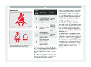 14
14 15
15 16
16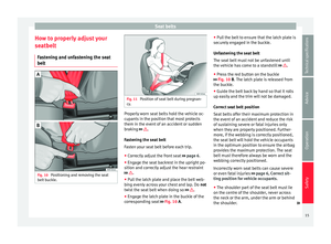 17
17 18
18 19
19 20
20 21
21 22
22 23
23 24
24 25
25 26
26 27
27 28
28 29
29 30
30 31
31 32
32 33
33 34
34 35
35 36
36 37
37 38
38 39
39 40
40 41
41 42
42 43
43 44
44 45
45 46
46 47
47 48
48 49
49 50
50 51
51 52
52 53
53 54
54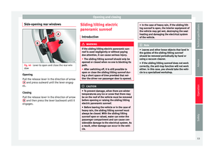 55
55 56
56 57
57 58
58 59
59 60
60 61
61 62
62 63
63 64
64 65
65 66
66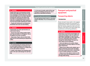 67
67 68
68 69
69 70
70 71
71 72
72 73
73 74
74 75
75 76
76 77
77 78
78 79
79 80
80 81
81 82
82 83
83 84
84 85
85 86
86 87
87 88
88 89
89 90
90 91
91 92
92 93
93 94
94 95
95 96
96 97
97 98
98 99
99 100
100 101
101 102
102 103
103 104
104 105
105 106
106 107
107 108
108 109
109 110
110 111
111 112
112 113
113 114
114 115
115 116
116 117
117 118
118 119
119 120
120 121
121 122
122 123
123 124
124 125
125 126
126 127
127 128
128 129
129 130
130 131
131 132
132 133
133 134
134 135
135 136
136 137
137 138
138 139
139 140
140 141
141 142
142 143
143 144
144 145
145 146
146 147
147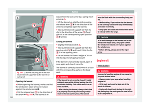 148
148 149
149 150
150 151
151 152
152 153
153 154
154 155
155 156
156 157
157 158
158 159
159 160
160 161
161 162
162 163
163 164
164 165
165 166
166 167
167 168
168 169
169 170
170 171
171 172
172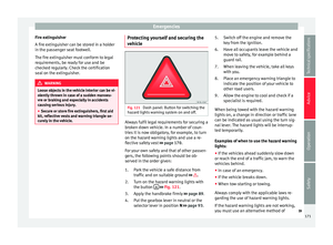 173
173 174
174 175
175 176
176 177
177 178
178 179
179 180
180 181
181 182
182 183
183 184
184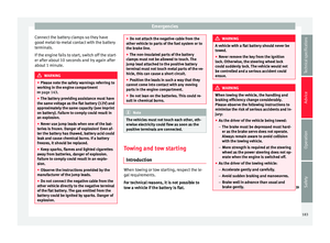 185
185 186
186 187
187 188
188 189
189 190
190 191
191 192
192 193
193 194
194 195
195 196
196 197
197 198
198 199
199 200
200 201
201 202
202 203
203 204
204 205
205 206
206 207
207 208
208 209
209 210
210 211
211 212
212 213
213 214
214 215
215 216
216 217
217 218
218