2014 NISSAN TEANA headlamp
[x] Cancel search: headlampPage 2385 of 4801
BOTH SIDE HEADLAMPS (LO) ARE NOT TURNED ONEXL-119
< SYMPTOM DIAGNOSIS >
C
D E
F
G H
I
J
K
M A
B
EXL
N
O P
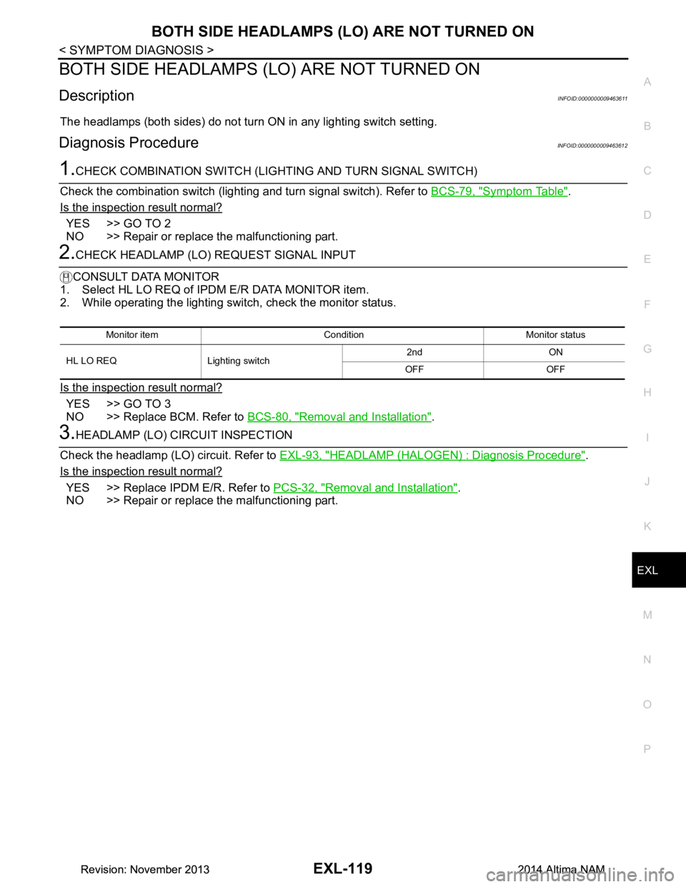
BOTH SIDE HEADLAMPS (L O) ARE NOT TURNED ON
DescriptionINFOID:0000000009463611
The headlamps (both sides) do not turn ON in any lighting switch setting.
Diagnosis ProcedureINFOID:0000000009463612
1.CHECK COMBINATION SWITCH (LIGHTING AND TURN SIGNAL SWITCH)
Check the combination switch (lighting and turn signal switch). Refer to BCS-79, "Symptom Table"
.
Is the inspection result normal?
YES >> GO TO 2
NO >> Repair or replace the malfunctioning part.
2.CHECK HEADLAMP (LO) REQUEST SIGNAL INPUT
CONSULT DATA MONITOR
1. Select HL LO REQ of IPDM E/R DATA MONITOR item.
2. While operating the lighting switch, check the monitor status.
Is the inspection result normal?
YES >> GO TO 3
NO >> Replace BCM. Refer to BCS-80, "Removal and Installation"
.
3.HEADLAMP (LO) CIRCUIT INSPECTION
Check the headlamp (LO) circuit. Refer to EXL-93, "HEADLAMP (HALOGEN) : Diagnosis Procedure"
.
Is the inspection result normal?
YES >> Replace IPDM E/R. Refer to PCS-32, "Removal and Installation".
NO >> Repair or replace the malfunctioning part.
Monitor item Condition Monitor status
HL LO REQ Lighting switch 2nd ON
OFF OFF
Revision: November 20132014 Altima NAMRevision: November 20132014 Altima NAM
Page 2388 of 4801
EXL-122
< PERIODIC MAINTENANCE >
HEADLAMP
PERIODIC MAINTENANCE
HEADLAMP
Aiming AdjustmentINFOID:0000000009463617
PREPARATION BEFORE ADJUSTING
Before performing aiming adjustment, check the following:
• Ensure all tires are inflated to correct pressure.
• Place vehicle and screen on level surface.
• Ensure there is no load in vehicle other than the driver (or equivalent weight placed in driver's position).
• Coolant and engine oil filled to correct level, and fuel tank full.
• Remove cargo and/or luggage to maintain an unloaded vehicle condition.
• Confirm spare tire, jack and tools are properly stowed.
• Carefully wipe off any dirt from headlamp lens. CAUTION:
Do not use organic solvent (thinner, gasoline etc.)
• Place a driver or equivalent weight of 68.5 kg (150 lb) on the driver seat.
• By hand, bounce the front and rear of the vehicle to settle the suspension and eliminate any static load.
• Place the front tires in the straight ahead position.
• Aim each headlamp individually and ensure other headlamp beam pattern is blocked from screen.
NOTE:
• For headlamp aiming details, refer to regulations in your area.
• By regulation, no means for horizontal aim adjustment is provided from the factory; only vertical aim is
adjustable.
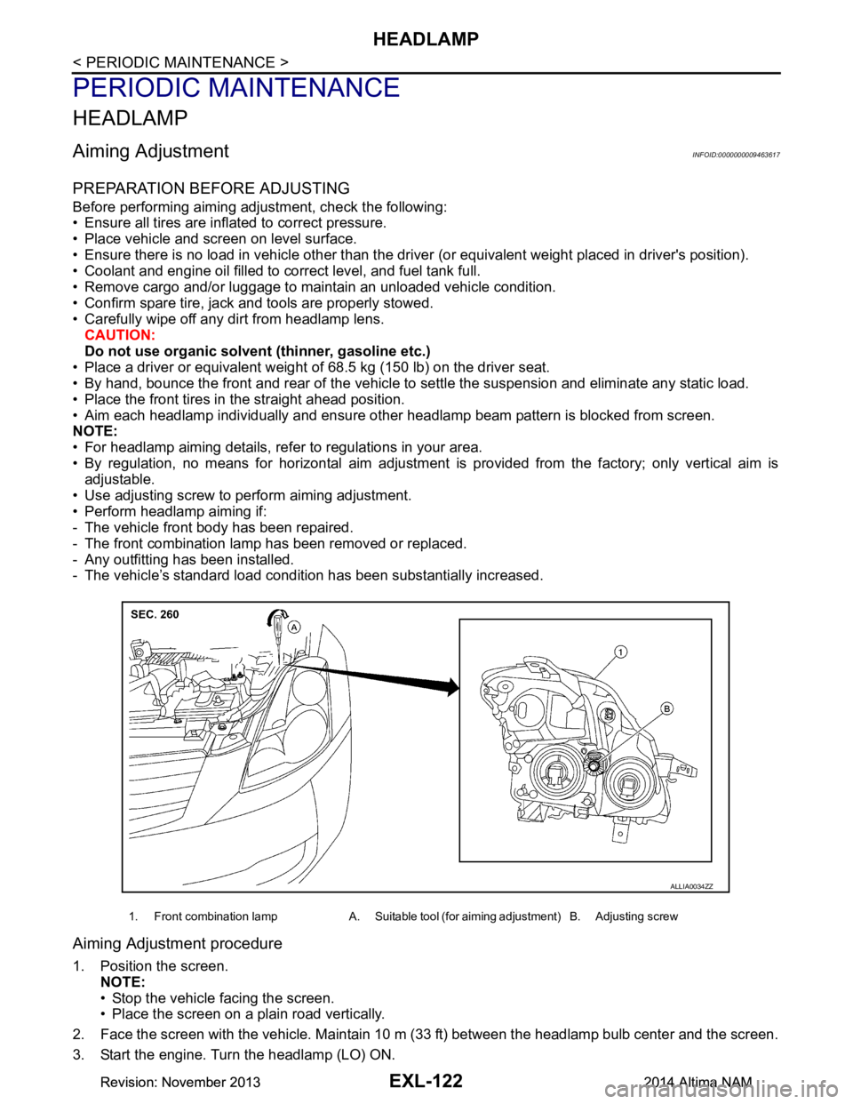
• Use adjusting screw to perform aiming adjustment.
• Perform headlamp aiming if:
- The vehicle front body has been repaired.
- The front combination lamp has been removed or replaced.
- Any outfitting has been installed.
- The vehicle’s standard load condition has been substantially increased.
Aiming Adjustment procedure
1. Position the screen.
NOTE:
• Stop the vehicle facing the screen.
• Place the screen on a plain road vertically.
2. Face the screen with the vehicle. Maintain 10 m (33 ft) between the headlamp bulb center and the screen.
3. Start the engine. Turn the headlamp (LO) ON.
1. Front combination lamp A. Suitable tool (for aiming adjustment) B. Adjusting screw
ALLIA0034ZZ
Revision: November 20132014 Altima NAMRevision: November 20132014 Altima NAM
Page 2389 of 4801
HEADLAMPEXL-123
< PERIODIC MAINTENANCE >
C
D E
F
G H
I
J
K
M A
B
EXL
N
O P
CAUTION:
Do not cover the lens surface with tape, etc. The lens is made of resin.
NOTE:
• Aim each headlamp individually and ensure other headlamp beam pattern is blocked from screen.
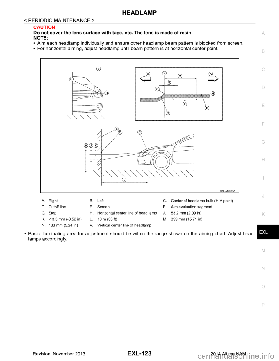
• For horizontal aiming, adjust headlamp until beam pattern is at horizontal center point.
• Basic illuminating area for adjustment should be with in the range shown on the aiming chart. Adjust head-
lamps accordingly.
A. Right B. Left C. Center of headlamp bulb (H-V point)
D. Cutoff line E. Screen F. Aim evaluation segment
G. Step H. Horizontal center line of head lamp J. 53.2 mm (2.09 in)
K. -13.3 mm (-0.52 in) L. 10 m (33 ft) M. 399 mm (15.71 in)
N. 133 mm (5.24 in) V. Vertical center line of headlamp
AWLIA1498ZZ
Revision: November 20132014 Altima NAMRevision: November 20132014 Altima NAM
Page 2390 of 4801
EXL-124
< PERIODIC MAINTENANCE >
FRONT FOG LAMP
FRONT FOG LAMP
Aiming AdjustmentINFOID:0000000009463618
PREPARATION BEFORE ADJUSTING
The fog lamp is a semi-sealed beam type which uses a replaceable halogen bulb. Before performing aiming
adjustment procedure, check the following:
• Ensure all tires are inflated to correct pressure.
• Place vehicle and screen on level surface.
• Ensure there is no load in vehicle other than the driver (or equivalent weight placed in driver's position).
• Coolant and engine oil filled to correct level, and fuel tank full.
• Remove cargo and/or luggage to maintain an unloaded vehicle condition.
• Confirm spare tire, jack and tools are properly stowed.
• Carefully wipe off any dirt from headlamp lens. CAUTION:
Do not use organic solvent (thinner, gasoline etc.)
• Place a driver or equivalent weight of 68.5 kg (150 lb) on the driver seat.
• By hand, bounce the front and rear of the vehicle to settle the suspension and eliminate any static load.
• Place the front tires in the straight ahead position.
• Aim each headlamp individually and ensure other headlamp beam pattern is blocked from screen.
NOTE:
• For headlamp aiming details, refer to regulations in your area.
• By regulation, no means for horizontal aim adjustment is provided from the factory; only vertical aim is
adjustable.
• Use adjusting screw to perform aiming adjustment.
• Perform headlamp aiming if:
- The vehicle front body has been repaired.
- The front combination lamp has been removed or replaced.
- Any outfitting has been installed.
- The vehicle’s standard load condition has been substantially increased.
Aiming Adjustment Procedure
1. Place the screen. NOTE:
• Stop the vehicle facing the wall.
• Place the board on a plain road vertically.
2. Face the vehicle with the screen. Maintain 7.62 m (25.0 ft) between the front fog lamp center and the
screen.
3. Start the engine. Turn the front fog lamp ON. NOTE:
Shut off the headlamp light with the board to prevent from illuminating the adjustment screen.
CAUTION:
Do not cover the lens surface with a tape etc. The lens is made of resin.
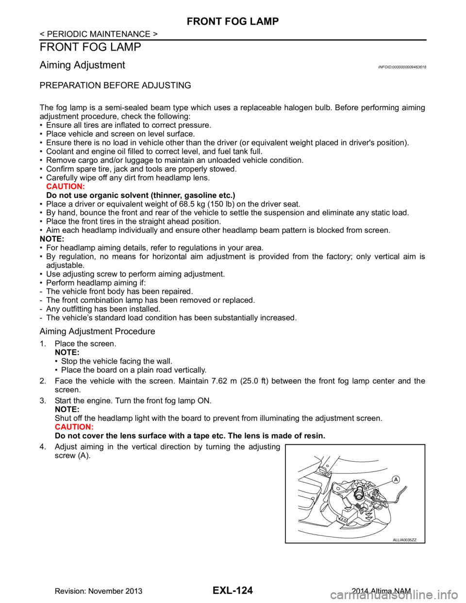
4. Adjust aiming in the vertical direction by turning the adjusting screw (A).
ALLIA0035ZZ
Revision: November 20132014 Altima NAMRevision: November 20132014 Altima NAM
Page 2393 of 4801
FRONT COMBINATION LAMPEXL-127
< REMOVAL AND INSTALLATION >
C
D E
F
G H
I
J
K
M A
B
EXL
N
O P
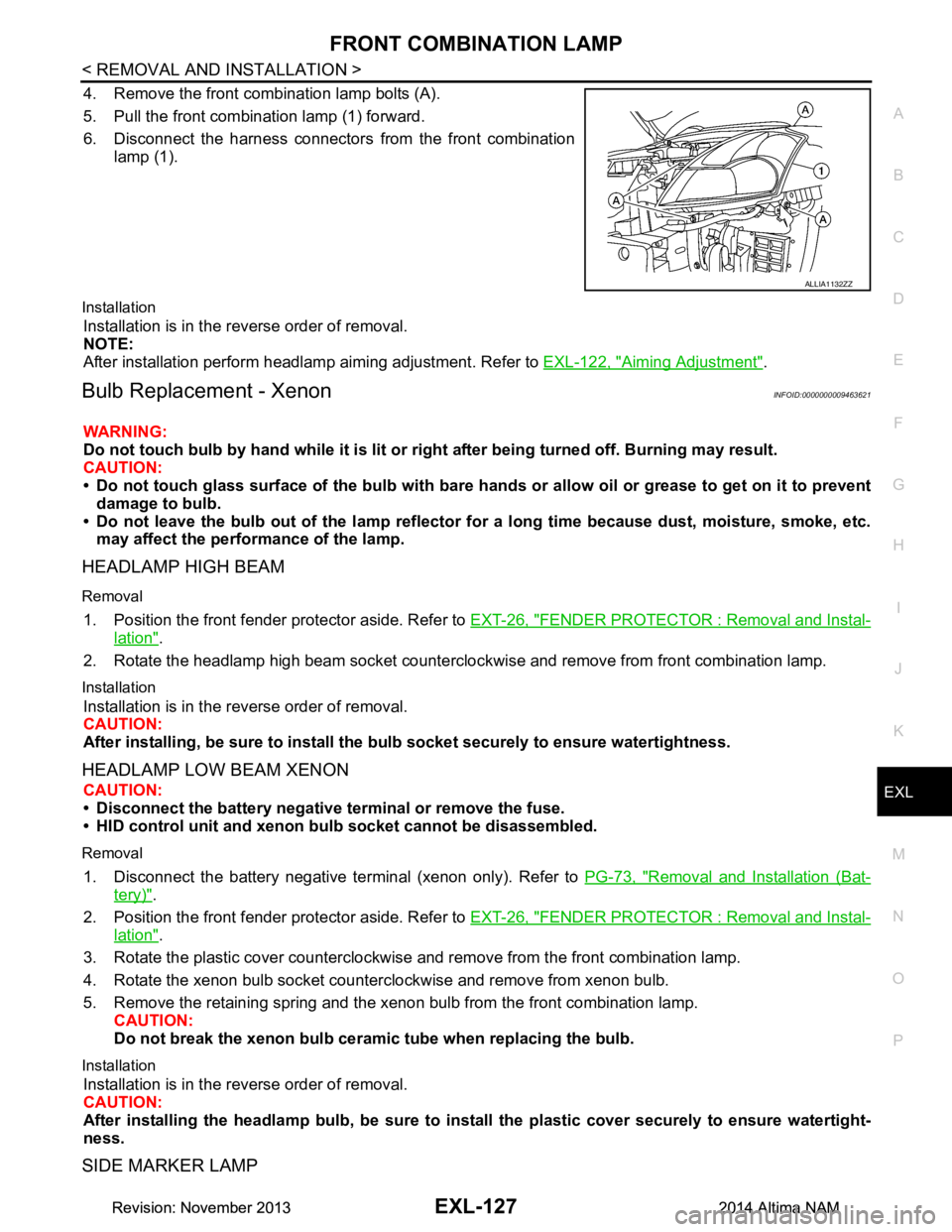
4. Remove the front combination lamp bolts (A).
5. Pull the front combination lamp (1) forward.
6. Disconnect the harness connectors from the front combination
lamp (1).
Installation
Installation is in the reverse order of removal.
NOTE:
After installation perform headlamp aiming adjustment. Refer to EXL-122, "Aiming Adjustment"
.
Bulb Replacement - XenonINFOID:0000000009463621
WARNING:
Do not touch bulb by hand while it is lit or right after being turned off. Burning may result.
CAUTION:
• Do not touch glass surface of the bulb with bare hand s or allow oil or grease to get on it to prevent
damage to bulb.
• Do not leave the bulb out of the lamp reflector fo r a long time because dust, moisture, smoke, etc.
may affect the performance of the lamp.
HEADLAMP HIGH BEAM
Removal
1. Position the front fender pr otector aside. Refer to EXT-26, "FENDER PROTECTOR : Removal and Instal-
lation".
2. Rotate the headlamp high beam socket countercloc kwise and remove from front combination lamp.
Installation
Installation is in the reverse order of removal.
CAUTION:
After installing, be sure to install the bulb socket securely to ensure watertightness.
HEADLAMP LOW BEAM XENON
CAUTION:
• Disconnect the battery negative terminal or remove the fuse.
• HID control unit and xenon bu lb socket cannot be disassembled.
Removal
1. Disconnect the battery negative te rminal (xenon only). Refer to PG-73, "Removal and Installation (Bat-
tery)".
2. Position the front fender pr otector aside. Refer to EXT-26, "FENDER PROTECTOR : Removal and Instal-
lation".
3. Rotate the plastic cover counterclockwise and remove from the front combination lamp.
4. Rotate the xenon bulb socket counterclockwise and remove from xenon bulb.
5. Remove the retaining spring and the xenon bulb from the front combination lamp. CAUTION:
Do not break the xenon bulb ceramic tube when replacing the bulb.
Installation
Installation is in the reverse order of removal.
CAUTION:
After installing the headlamp bulb, be sure to inst all the plastic cover securely to ensure watertight-
ness.
SIDE MARKER LAMP
ALLIA1132ZZ
Revision: November 20132014 Altima NAMRevision: November 20132014 Altima NAM
Page 2395 of 4801
FRONT COMBINATION LAMPEXL-129
< REMOVAL AND INSTALLATION >
C
D E
F
G H
I
J
K
M A
B
EXL
N
O P
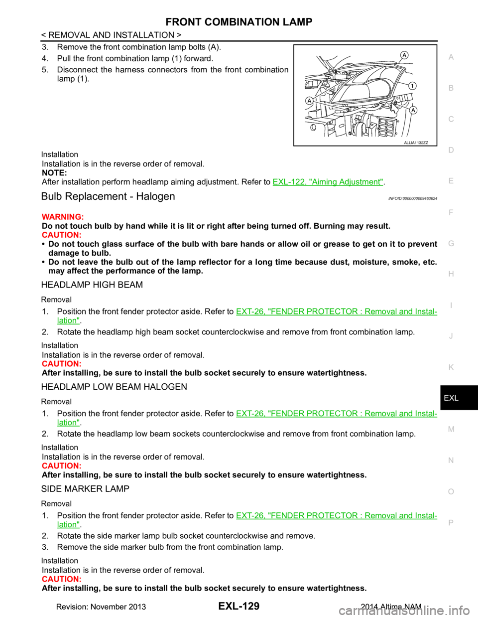
3. Remove the front combination lamp bolts (A).
4. Pull the front combination lamp (1) forward.
5. Disconnect the harness connectors from the front combination
lamp (1).
Installation
Installation is in the reverse order of removal.
NOTE:
After installation perform headlamp aiming adjustment. Refer to EXL-122, "Aiming Adjustment"
.
Bulb Replacement - HalogenINFOID:0000000009463624
WARNING:
Do not touch bulb by hand while it is lit or right after being turned off. Burning may result.
CAUTION:
• Do not touch glass surface of the bulb with bare hand s or allow oil or grease to get on it to prevent
damage to bulb.
• Do not leave the bulb out of the lamp reflector fo r a long time because dust, moisture, smoke, etc.
may affect the performance of the lamp.
HEADLAMP HIGH BEAM
Removal
1. Position the front fender pr otector aside. Refer to EXT-26, "FENDER PROTECTOR : Removal and Instal-
lation".
2. Rotate the headlamp high beam socket countercloc kwise and remove from front combination lamp.
Installation
Installation is in the reverse order of removal.
CAUTION:
After installing, be sure to install the bulb socket securely to ensure watertightness.
HEADLAMP LOW BEAM HALOGEN
Removal
1. Position the front fender protector aside. Refer to EXT-26, "FENDER PROTECTOR : Removal and Instal-
lation".
2. Rotate the headlamp low beam sockets countercloc kwise and remove from front combination lamp.
Installation
Installation is in the reverse order of removal.
CAUTION:
After installing, be sure to install the bulb socket securely to ensure watertightness.
SIDE MARKER LAMP
Removal
1. Position the front fender protector aside. Refer to EXT-26, "FENDER PROTECTOR : Removal and Instal-
lation".
2. Rotate the side marker lamp bulb socket counterclockwise and remove.
3. Remove the side marker bulb from the front combination lamp.
Installation
Installation is in the reverse order of removal.
CAUTION:
After installing, be sure to install the bulb socket securely to ensure watertightness.
ALLIA1132ZZ
Revision: November 20132014 Altima NAMRevision: November 20132014 Altima NAM
Page 2529 of 4801

GI-1
GENERAL INFORMATION
C
D E
F
G H
I
J
K L
M B
GI
SECTION GI
N
O P
CONTENTS
GENERAL INFORMATION
HOW TO USE THIS MANU AL ......................3
HOW TO USE THIS MANUAL ....................... .....3
Description .......................................................... ......3
Terms ........................................................................3
Units ..........................................................................3
Contents ....................................................................3
Relation between Illustrations and Descriptions .......4
Components ..............................................................4
HOW TO FOLLOW TROUBLE DIAGNOSES .....6
Description ................................................................6
How to Follow Test Groups in Trouble Diagnosis ......6
Key to Symbols Signifying Measurements or Pro-
cedures ............................................................... ......
7
HOW TO READ WIRING DIAGRAMS ................9
Connector symbols ............................................. ......9
Sample/wiring diagram -example- ...........................10
Description ..............................................................11
ABBREVIATIONS .......................................... ....13
Abbreviation List .................................................. ....13
TIGHTENING TORQUE OF STANDARD
BOLTS ............................................................ ....
18
Description .......................................................... ....18
Tightening Torque Table (New Standard Includ-
ed) ....................................................................... ....
18
RECOMMENDED CHEMICAL PRODUCTS
AND SEALANTS ............................................ ....
21
Recommended Chemical Products and Sealants ....21
VEHICLE INFORMATION ............................22
IDENTIFICATION INFORMATION ................. ....22
Model Variation ................................................... ....22
Identification Number ..............................................23
Identification Plate ...................................................24
Engine Serial Number .............................................24
CVT Number ...........................................................25
Dimensions .......................................................... ....25
Wheels & Tires ........................................................25
PRECAUTION ..............................................26
PRECAUTIONS .................................................26
Description ........................................................... ....26
Precaution for Supplemental Restraint System
(SRS) "AIR BAG" and "SEAT BELT PRE-TEN-
SIONER" ............................................................. ....
26
Precautions For Xenon Headlamp Service .............26
Procedures without Cowl Top Cover .......................27
Cautions in Removing Battery Terminal and AV
Control Unit .......................................................... ....
27
General Precautions ................................................27
Three Way Catalyst .................................................29
Fuel (Regular Unleaded Gasoline Recommend-
ed) QR25DE ........................................................ ....
29
Fuel (Regular Unleaded Gasoline Recommend-
ed) VQ35DE ........................................................ ....
29
Multiport Fuel Injection System or Engine Control
System ................................................................. ....
29
Hoses ......................................................................29
Engine Oils ..............................................................30
Air Conditioning .......................................................31
LIFTING POINT .................................................32
Special Service Tool ................................................32
Pantograph Jack ......................................................32
Garage Jack and Safety Stand ................................33
2-Pole Lift ................................................................34
Board-on Lift ............................................................35
TOW TRUCK TOWING .....................................36
Tow Truck Towing ...................................................36
Vehicle Recovery (Freeing a Stuck Vehicle) ...........36
WIRING DIAGRAM ......................................38
CONSULT CHECKING SYSTEM .....................38
Wiring Diagram .................................................... ....38
Revision: November 20132014 Altima NAMRevision: November 20132014 Altima NAM
Page 2554 of 4801
GI-26
< PRECAUTION >
PRECAUTIONS
PRECAUTION
PRECAUTIONS
DescriptionINFOID:0000000009462991
Observe the following precautions to ensure safe and proper servicing. These precautions are not
described in each individual section.
Precaution for Supplemental Restraint Syst em (SRS) "AIR BAG" and "SEAT BELT
PRE-TENSIONER"
INFOID:0000000009462992
The Supplemental Restraint System such as “A IR BAG” and “SEAT BELT PRE-TENSIONER”, used along
with a front seat belt, helps to reduce the risk or severi ty of injury to the driver and front passenger for certain
types of collision. Information necessary to service the system safely is included in the SR and SB section of
this Service Manual.
WARNING:
• To avoid rendering the SRS inopera tive, which could increase the risk of personal injury or death in
the event of a collision which would result in air bag inflation, all maintenance must be performed by
an authorized NISS AN/INFINITI dealer.
• Improper maintenance, including in correct removal and installation of the SRS, can lead to personal
injury caused by unintent ional activation of the system. For re moval of Spiral Cable and Air Bag
Module, see the SR section.
• Do not use electrical test equipmen t on any circuit related to the SRS unless instructed to in this
Service Manual. SRS wiring harn esses can be identified by yellow and/or orange harnesses or har-
ness connectors.
PRECAUTIONS WHEN USING POWER TOOLS (AIR OR ELECTRIC) AND HAMMERS
WARNING:
• When working near the Airbag Diagnosis Sensor Unit or other Airbag System sensors with the Igni-
tion ON or engine running, DO NOT use air or electri c power tools or strike near the sensor(s) with a
hammer. Heavy vibration could activate the sensor( s) and deploy the air bag(s), possibly causing
serious injury.
• When using air or electric power tools or hammers , always switch the Ignition OFF, disconnect the
battery and wait at least 3 minutes before performing any service.
Precautions For Xeno n Headlamp ServiceINFOID:0000000009462993
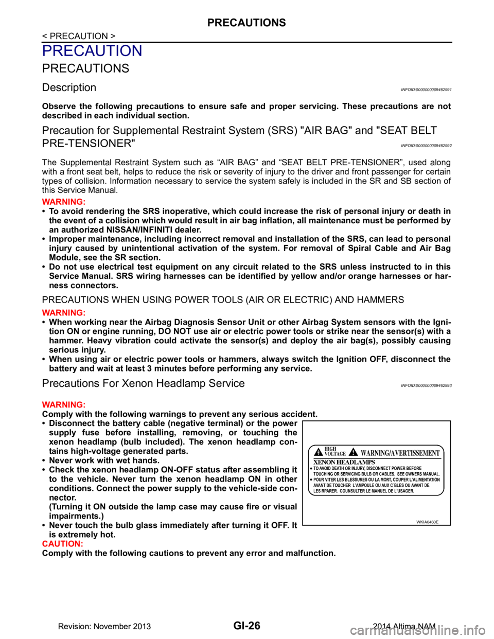
WARNING:
Comply with the following warnings to prevent any serious accident.
• Disconnect the battery cable (n egative terminal) or the power
supply fuse before in stalling, removing, or touching the
xenon headlamp (bulb included) . The xenon headlamp con-
tains high-voltage generated parts.
• Never work with wet hands.
• Check the xenon headlamp ON-OFF status after assembling it to the vehicle. Never turn the xenon headlamp ON in other
conditions. Connect the power supply to the vehicle-side con-
nector.
(Turning it ON outside the la mp case may cause fire or visual
impairments.)
• Never touch the bulb glass immediately after turning it OFF. It is extremely hot.
CAUTION:
Comply with the following cautions to prevent any error and malfunction.
WKIA0460E
Revision: November 20132014 Altima NAMRevision: November 20132014 Altima NAM