2014 NISSAN TEANA headlamp
[x] Cancel search: headlampPage 3949 of 4801
SEC-124
< DTC/CIRCUIT DIAGNOSIS >
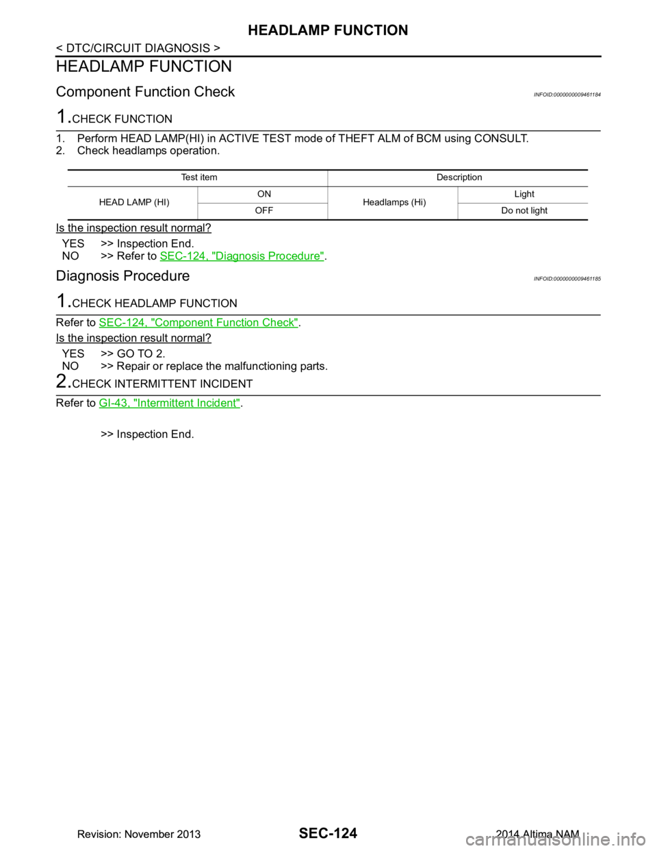
HEADLAMP FUNCTION
HEADLAMP FUNCTION
Component Function CheckINFOID:0000000009461184
1.CHECK FUNCTION
1. Perform HEAD LAMP(HI) in ACTIVE TEST mode of THEFT ALM of BCM using CONSULT.
2. Check headlamps operation.
Is the inspection result normal?
YES >> Inspection End.
NO >> Refer to SEC-124, "Diagnosis Procedure"
.
Diagnosis ProcedureINFOID:0000000009461185
1.CHECK HEADLAMP FUNCTION
Refer to SEC-124, "Component Function Check"
.
Is the inspection result normal?
YES >> GO TO 2.
NO >> Repair or replace the malfunctioning parts.
2.CHECK INTERMITTENT INCIDENT
Refer to GI-43, "Intermittent Incident"
.
>> Inspection End.
Te s t i t e m D e s c r i p t i o n
HEAD LAMP (HI) ON
Headlamps (Hi) Light
OFF Do not light
Revision: November 20132014 Altima NAMRevision: November 20132014 Altima NAM
Page 3958 of 4801
VEHICLE SECURITY ALARM DOES NOT ACTIVATE
SEC-133
< SYMPTOM DIAGNOSIS >
C
D E
F
G H
I
J
L
M A
B
SEC
N
O P
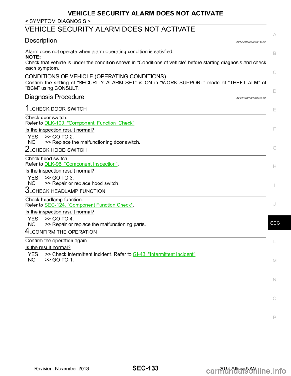
VEHICLE SECURITY ALAR M DOES NOT ACTIVATE
DescriptionINFOID:0000000009461204
Alarm does not operate when alarm operating condition is satisfied.
NOTE:
Check that vehicle is under the condition shown in “C onditions of vehicle” before starting diagnosis and check
each symptom.
CONDITIONS OF VEHICLE (OPERATING CONDITIONS)
Confirm the setting of “SECURITY ALARM SET” is ON in “WORK SUPPORT” mode of “THEFT ALM” of
“BCM” using CONSULT.
Diagnosis ProcedureINFOID:0000000009461205
1.CHECK DOOR SWITCH
Check door switch.
Refer to DLK-100, "Component Function Check"
.
Is the inspection result normal?
YES >> GO TO 2.
NO >> Replace the malfunctioning door switch.
2.CHECK HOOD SWITCH
Check hood switch.
Refer to DLK-96, "Component Inspection"
.
Is the inspection result normal?
YES >> GO TO 3.
NO >> Repair or replace hood switch.
3.CHECK HEADLAMP FUNCTION
Check headlamp function.
Refer to SEC-124, "Component Function Check"
.
Is the inspection result normal?
YES >> GO TO 4.
NO >> Repair or replace the malfunctioning parts.
4.CONFIRM THE OPERATION
Confirm the operation again.
Is the result normal?
YES >> Check intermittent incident. Refer to GI-43, "Intermittent Incident".
NO >> GO TO 1.
Revision: November 20132014 Altima NAMRevision: November 20132014 Altima NAM
Page 3959 of 4801
SEC-134
< SYMPTOM DIAGNOSIS >
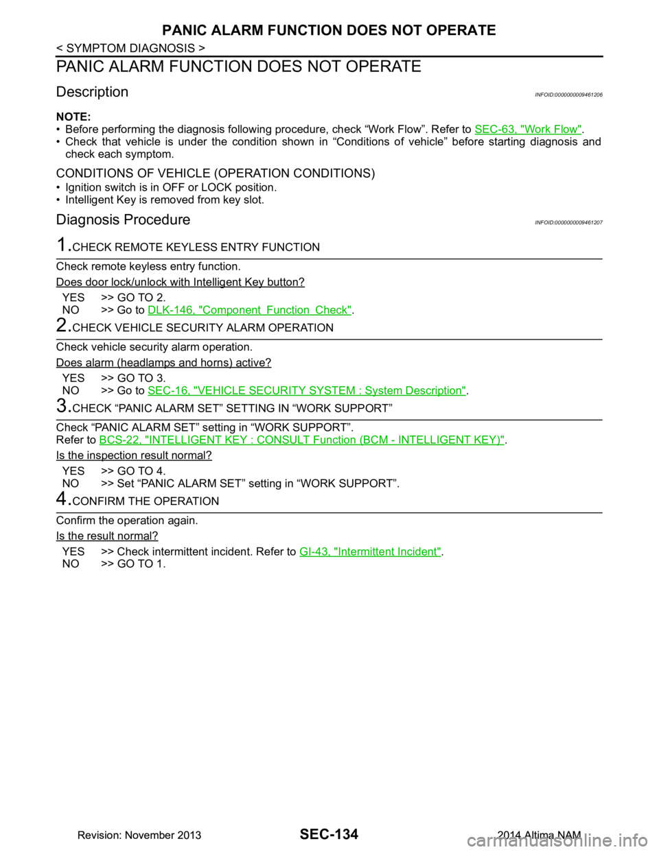
PANIC ALARM FUNCTION DOES NOT OPERATE
PANIC ALARM FUNCTION DOES NOT OPERATE
DescriptionINFOID:0000000009461206
NOTE:
• Before performing the diagnosis following procedure, check “Work Flow”. Refer to SEC-63, "Work Flow"
.
• Check that vehicle is under the condition shown in “Conditions of vehicle” before starting diagnosis and
check each symptom.
CONDITIONS OF VEHICLE (OPERATION CONDITIONS)
• Ignition switch is in OFF or LOCK position.
• Intelligent Key is removed from key slot.
Diagnosis ProcedureINFOID:0000000009461207
1.CHECK REMOTE KEYL ESS ENTRY FUNCTION
Check remote keyless entry function.
Does door lock/unlock with Intelligent Key button?
YES >> GO TO 2.
NO >> Go to DLK-146, "Component Function Check"
.
2.CHECK VEHICLE SECURITY ALARM OPERATION
Check vehicle security alarm operation.
Does alarm (headlamps and horns) active?
YES >> GO TO 3.
NO >> Go to SEC-16, "VEHICLE SECURITY SYSTEM : System Description"
.
3.CHECK “PANIC ALARM SET” SETTING IN “WORK SUPPORT”
Check “PANIC ALARM SET” setting in “WORK SUPPORT”.
Refer to BCS-22, "INTELLIGENT KEY : CONSULT Function (BCM - INTELLIGENT KEY)"
.
Is the inspection result normal?
YES >> GO TO 4.
NO >> Set “PANIC ALARM SET” setting in “WORK SUPPORT”.
4.CONFIRM THE OPERATION
Confirm the operation again.
Is the result normal?
YES >> Check intermittent incident. Refer to GI-43, "Intermittent Incident".
NO >> GO TO 1.
Revision: November 20132014 Altima NAMRevision: November 20132014 Altima NAM
Page 4655 of 4801

WCS
DIAGNOSIS SYSTEM (BCM)WCS-13
< SYSTEM DESCRIPTION >
C
D E
F
G H
I
J
K L
M B
A
O P
DIAGNOSIS SYSTEM (BCM)
COMMON ITEM
COMMON ITEM : CONSULT Function (BCM - COMMON ITEM)INFOID:0000000009941192
CAUTION:
After disconnecting the CONSULT vehicle interface (VI) from the data link connector, the ignition must
be cycled OFF → ON (for at least 5 seconds) → OFF. If this step is not performed, the BCM may not go
to ”sleep mode”, potentiall y causing a discharged battery and a no-start condition.
APPLICATION ITEM
CONSULT performs the following functions via CAN communication with BCM.
SYSTEM APPLICATION
BCM can perform the following functions.
Direct Diagnostic Mode Description
Ecu Identification The BCM part number is displayed.
Self Diagnostic Result The BCM self diagnostic results are displayed.
Data Monitor The BCM input/output data is displayed in real time.
Active Test The BCM activates outputs to test components.
Work support The settings for BCM functions can be changed.
Configuration • The vehicle specification can be read and saved.
• The vehicle specification can be written when replacing BCM.
CAN Diag Support Mntr The result of transmit/receive diagnosis of CAN communication is displayed.
System Sub System Direct Diagnostic Mode
Ecu Identification
Self Diagnostic Result
Data Monitor
Active Test
Work support
Configuration
CAN Diag Su pport Mntr
Door lock DOOR LOCK ××××
Rear window defogger REAR DEFOGGER ×××
Warning chime BUZZER ××
Interior room lamp timer INT LAMP ×××
Remote keyless entry system MULTI REMOTE ENT ×××
Exterior lamp HEADLAMP ×××
Wiper and washer WIPER ×××
Turn signal and hazard warning lamps FLASHER ××
Air conditioner AIR CONDITIONER ×
Intelligent Key system INTELLIGENT KEY ××××
Combination switch COMB SW ×
BCM BCM × × ×××
Immobilizer IMMU ×××
Interior room lamp battery saver BATTERY SAVER ××
Trunk open TRUNK ×
Vehicle security system THEFT ALM ×××
Revision: November 20132014 Altima NAMRevision: November 20132014 Altima NAM
Page 4674 of 4801
WCS-32
< SYMPTOM DIAGNOSIS >
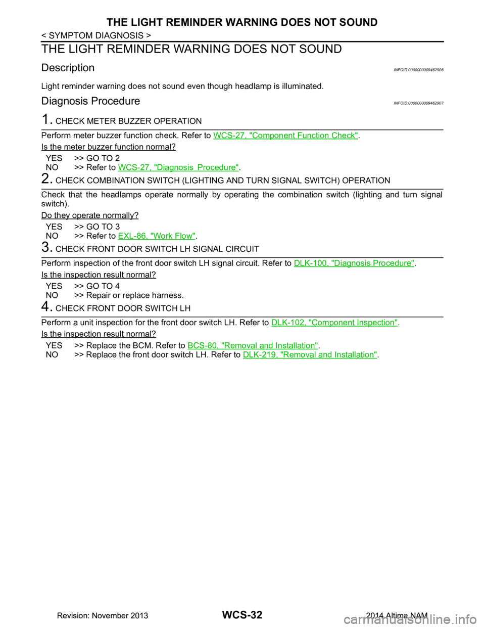
THE LIGHT REMINDER WARNING DOES NOT SOUND
THE LIGHT REMINDER WARNING DOES NOT SOUND
DescriptionINFOID:0000000009462906
Light reminder warning does not sound even though headlamp is illuminated.
Diagnosis ProcedureINFOID:0000000009462907
1. CHECK METER BUZZER OPERATION
Perform meter buzzer function check. Refer to WCS-27, "Component Function Check"
.
Is the meter buzzer function normal?
YES >> GO TO 2
NO >> Refer to WCS-27, "Diagnosis Procedure"
.
2. CHECK COMBINATION SWITCH (LIGHTIN G AND TURN SIGNAL SWITCH) OPERATION
Check that the headlamps operate normally by operati ng the combination switch (lighting and turn signal
switch).
Do they operate normally?
YES >> GO TO 3
NO >> Refer to EXL-86, "Work Flow"
.
3. CHECK FRONT DOOR SWITCH LH SIGNAL CIRCUIT
Perform inspection of the front door s witch LH signal circuit. Refer to DLK-100, "Diagnosis Procedure"
.
Is the inspection result normal?
YES >> GO TO 4
NO >> Repair or replace harness.
4. CHECK FRONT DOOR SWITCH LH
Perform a unit inspection for the front door switch LH. Refer to DLK-102, "Component Inspection"
.
Is the inspection result normal?
YES >> Replace the BCM. Refer to BCS-80, "Removal and Installation".
NO >> Replace the front door switch LH. Refer to DLK-219, "Removal and Installation"
.
Revision: November 20132014 Altima NAMRevision: November 20132014 Altima NAM
Page 4685 of 4801

WT-10
< SYSTEM DESCRIPTION >
DIAGNOSIS SYSTEM (BCM)
DIAGNOSIS SYSTEM (BCM)
COMMON ITEM
COMMON ITEM : CONSULT Function (BCM - COMMON ITEM)INFOID:0000000009955585
CAUTION:
After disconnecting the CONSULT vehicle interface (VI) from the data link connector, the ignition must
be cycled OFF → ON (for at least 5 seconds) → OFF. If this step is not performed, the BCM may not go
to ”sleep mode”, potentially causing a di scharged battery and a no-start condition.
APPLICATION ITEM
CONSULT performs the following functions via CAN communication with BCM.
SYSTEM APPLICATION
BCM can perform the following functions.
Direct Diagnostic Mode Description
Ecu Identification The BCM part number is displayed.
Self Diagnostic Result The BCM self diagnostic results are displayed.
Data Monitor The BCM input/output data is displayed in real time.
Active Test The BCM activates outputs to test components.
Work support The settings for BCM functions can be changed.
Configuration • The vehicle specification can be read and saved.
• The vehicle specification can be written when replacing BCM.
CAN Diag Support Mntr The result of transmit/receive diagnosis of CAN communication is displayed.
System Sub System Direct Diagnostic Mode
Ecu Identification
Self Diagnostic Result
Data Monitor
Active Test
Work support
Configuration
CAN Diag Su pport Mntr
Door lock DOOR LOCK ××××
Rear window defogger REAR DEFOGGER ×××
Warning chime BUZZER ××
Interior room lamp timer INT LAMP ×××
Remote keyless entry system MULTI REMOTE ENT ×××
Exterior lamp HEADLAMP ×××
Wiper and washer WIPER ×××
Turn signal and hazard warning lamps FLASHER ××
Air conditioner AIR CONDITIONER ×
Intelligent Key system INTELLIGENT KEY ××××
Combination switch COMB SW ×
BCM BCM × × ×××
Immobilizer IMMU ×××
Interior room lamp battery saver BATTERY SAVER ××
Trunk open TRUNK ×
Vehicle security system THEFT ALM ×××
Revision: November 20132014 Altima NAMRevision: November 20132014 Altima NAM
Page 4745 of 4801

WW-10
< SYSTEM DESCRIPTION >
DIAGNOSIS SYSTEM (BCM)
DIAGNOSIS SYSTEM (BCM)
COMMON ITEM
COMMON ITEM : CONSULT Function (BCM - COMMON ITEM)INFOID:0000000009944151
CAUTION:
After disconnecting the CONSULT vehicle interface (VI) from the data link connector, the ignition must
be cycled OFF → ON (for at least 5 seconds) → OFF. If this step is not performed, the BCM may not go
to ”sleep mode”, potentially causing a di scharged battery and a no-start condition.
APPLICATION ITEM
CONSULT performs the following functions via CAN communication with BCM.
SYSTEM APPLICATION
BCM can perform the following functions.
Direct Diagnostic Mode Description
Ecu Identification The BCM part number is displayed.
Self Diagnostic Result The BCM self diagnostic results are displayed.
Data Monitor The BCM input/output data is displayed in real time.
Active Test The BCM activates outputs to test components.
Work support The settings for BCM functions can be changed.
Configuration • The vehicle specification can be read and saved.
• The vehicle specification can be written when replacing BCM.
CAN Diag Support Mntr The result of transmit/receive diagnosis of CAN communication is displayed.
System Sub System Direct Diagnostic Mode
Ecu Identification
Self Diagnostic Result
Data Monitor
Active Test
Work support
Configuration
CAN Diag Su pport Mntr
Door lock DOOR LOCK ××××
Rear window defogger REAR DEFOGGER ×××
Warning chime BUZZER ××
Interior room lamp timer INT LAMP ×××
Remote keyless entry system MULTI REMOTE ENT ×××
Exterior lamp HEADLAMP ×××
Wiper and washer WIPER ×××
Turn signal and hazard warning lamps FLASHER ××
Air conditioner AIR CONDITIONER ×
Intelligent Key system INTELLIGENT KEY ××××
Combination switch COMB SW ×
BCM BCM × × ×××
Immobilizer IMMU ×××
Interior room lamp battery saver BATTERY SAVER ××
Trunk open TRUNK ×
Vehicle security system THEFT ALM ×××
Revision: November 20132014 Altima NAMRevision: November 20132014 Altima NAM
Page 4747 of 4801
WW-12
< SYSTEM DESCRIPTION >
DIAGNOSIS SYSTEM (IPDM E/R)
DIAGNOSIS SYSTEM (IPDM E/R)
Diagnosis DescriptionINFOID:0000000009944155
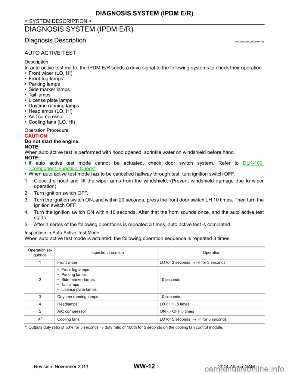
AUTO ACTIVE TEST
Description
In auto active test mode, the IPDM E/R sends a drive signal to the follo wing systems to check their operation.
• Front wiper (LO, HI)
• Front fog lamps
• Parking lamps
• Side marker lamps
• Tail lamps
• License plate lamps
• Daytime running lamps
• Headlamps (LO, HI)
• A/C compressor
• Cooling fans (LO, HI)
Operation Procedure
CAUTION:
Do not start the engine.
NOTE:
When auto active test is performed with hood opened, sprinkle water on windshield before hand.
NOTE:
• If auto active test mode cannot be actuat ed, check door switch system. Refer to DLK-100,
"Component Function Check".
• When auto active test mode has to be cancelled halfway through test, turn ignition switch OFF.
1. Close the hood and lift the wiper arms from the windshield. (Prevent windshield damage due to wiper
operation)
2. Turn ignition switch OFF.
3. Turn the ignition switch ON, and within 20 seconds, press the front door switch LH 10 times. Then turn the ignition switch OFF.
4. Turn the ignition switch ON within 10 seconds. Af ter that the horn sounds once, and the auto active test
starts.
5. After a series of the following operations is repeated 3 times, auto active test is completed.
Inspection in Auto Active Test Mode
When auto active test mode is actuated, the following operation sequence is repeated 3 times.
*: Outputs duty ratio of 50% for 5 seconds → duty ratio of 100% for 5 seconds on the cooling fan control module.
Operation se-
quence Inspection Location Operation
1 Front wiper LO for 3 seconds → HI for 3 seconds
2 •Front fog lamps
• Parking lamps
• Side marker lamps
•Tail lamps
• License plate lamps 10 seconds
3 Daytime running lamps 10 seconds
4 Headlamps LO ⇔ HI 5 times
5 A/C compressor ON ⇔ OFF 5 times
6
*Cooling fans LO for 5 seconds → HI for 5 seconds
Revision: November 20132014 Altima NAMRevision: November 20132014 Altima NAM