2014 NISSAN TEANA headlamp
[x] Cancel search: headlampPage 2773 of 4801
![NISSAN TEANA 2014 Service Manual
HAC-124
< SYSTEM DESCRIPTION >[MANUAL AIR CONDITIONER]
DIAGNOSIS SYSTEM (BCM)
DIAGNOSIS SYSTEM (BCM)
CONSULT Function (BCM - COMMON ITEM)INFOID:0000000009958322
CAUTION:
After disconnecting the CONS NISSAN TEANA 2014 Service Manual
HAC-124
< SYSTEM DESCRIPTION >[MANUAL AIR CONDITIONER]
DIAGNOSIS SYSTEM (BCM)
DIAGNOSIS SYSTEM (BCM)
CONSULT Function (BCM - COMMON ITEM)INFOID:0000000009958322
CAUTION:
After disconnecting the CONS](/manual-img/5/57390/w960_57390-2772.png)
HAC-124
< SYSTEM DESCRIPTION >[MANUAL AIR CONDITIONER]
DIAGNOSIS SYSTEM (BCM)
DIAGNOSIS SYSTEM (BCM)
CONSULT Function (BCM - COMMON ITEM)INFOID:0000000009958322
CAUTION:
After disconnecting the CONSULT vehicle interface (VI) from the data link connector, the ignition must
be cycled OFF → ON (for at least 5 seconds) → OFF. If this step is not performed, the BCM may not go
to ”sleep mode”, potentially causing a di scharged battery and a no-start condition.
APPLICATION ITEM
CONSULT performs the following functions via CAN communication with BCM.
SYSTEM APPLICATION
BCM can perform the following functions.
Direct Diagnostic Mode Description
Ecu Identification The BCM part number is displayed.
Self Diagnostic Result The BCM self diagnostic results are displayed.
Data Monitor The BCM input/output data is displayed in real time.
Active Test The BCM activates outputs to test components.
Work support The settings for BCM functions can be changed.
Configuration • The vehicle specification can be read and saved.
• The vehicle specification can be written when replacing BCM.
CAN Diag Support Mntr The result of transmit/receive diagnosis of CAN communication is displayed.
System Sub System Direct Diagnostic Mode
Ecu Identification
Self Diagnostic Result
Data Monitor
Active Test
Work support
Configuration
CAN Diag Support Mntr
Door lock DOOR LOCK ××××
Rear window defogger REAR DEFOGGER ×××
Warning chime BUZZER ××
Interior room lamp timer INT LAMP ×××
Remote keyless entry system MULTI REMOTE ENT ×××
Exterior lamp HEADLAMP ×××
Wiper and washer WIPER ×××
Turn signal and hazard warning lamps FLASHER ××
Air conditioner AIR CONDITIONER ×
Intelligent Key system INTELLIGENT KEY ××××
Combination switch COMB SW ×
BCM BCM × × ×××
Immobilizer IMMU ×××
Interior room lamp battery saver BATTERY SAVER ××
Trunk open TRUNK ×
Vehicle security system THEFT ALM ×××
RAP system RETAINED PWR ×
Revision: November 20132014 Altima NAMRevision: November 20132014 Altima NAM
Page 2832 of 4801

DIAGNOSIS SYSTEM (BCM)INL-11
< SYSTEM DESCRIPTION >
C
D E
F
G H
I
J
K
M A
B
INL
N
O P
DIAGNOSIS SYSTEM (BCM)
COMMON ITEM
COMMON ITEM : CONSULT Function (BCM - COMMON ITEM)INFOID:0000000009956797
CAUTION:
After disconnecting the CONSULT vehicle interface (VI) from the data link connector, the ignition must
be cycled OFF → ON (for at least 5 seconds) → OFF. If this step is not performed, the BCM may not go
to ”sleep mode”, potentiall y causing a discharged battery and a no-start condition.
APPLICATION ITEM
CONSULT performs the following functions via CAN communication with BCM.
SYSTEM APPLICATION
BCM can perform the following functions.
Direct Diagnostic Mode Description
Ecu Identification The BCM part number is displayed.
Self Diagnostic Result The BCM self diagnostic results are displayed.
Data Monitor The BCM input/output data is displayed in real time.
Active Test The BCM activates outputs to test components.
Work support The settings for BCM functions can be changed.
Configuration • The vehicle specification can be read and saved.
• The vehicle specification can be written when replacing BCM.
CAN Diag Support Mntr The result of transmit/receive diagnosis of CAN communication is displayed.
System Sub System Direct Diagnostic Mode
Ecu Identification
Self Diagnostic Result
Data Monitor
Active Test
Work support
Configuration
CAN Diag Su pport Mntr
Door lock DOOR LOCK ××××
Rear window defogger REAR DEFOGGER ×××
Warning chime BUZZER ××
Interior room lamp timer INT LAMP ×××
Remote keyless entry system MULTI REMOTE ENT ×××
Exterior lamp HEADLAMP ×××
Wiper and washer WIPER ×××
Turn signal and hazard warning lamps FLASHER ××
Air conditioner AIR CONDITIONER ×
Intelligent Key system INTELLIGENT KEY ××××
Combination switch COMB SW ×
BCM BCM × × ×××
Immobilizer IMMU ×××
Interior room lamp battery saver BATTERY SAVER ××
Trunk open TRUNK ×
Vehicle security system THEFT ALM ×××
Revision: November 20132014 Altima NAMRevision: November 20132014 Altima NAM
Page 2838 of 4801

DIAGNOSIS SYSTEM (IPDM E/R)INL-17
< SYSTEM DESCRIPTION >
C
D E
F
G H
I
J
K
M A
B
INL
N
O P
DIAGNOSIS SYSTEM (IPDM E/R)
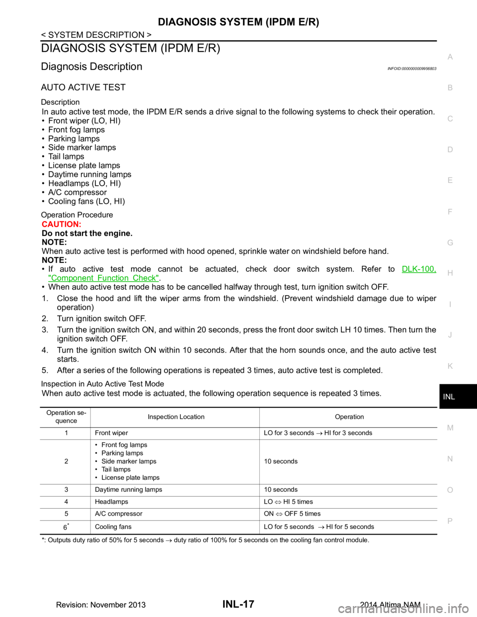
Diagnosis DescriptionINFOID:0000000009956803
AUTO ACTIVE TEST
Description
In auto active test mode, the IPDM E/R sends a drive signal to the following systems to check their operation.
• Front wiper (LO, HI)
• Front fog lamps
• Parking lamps
• Side marker lamps
• Tail lamps
• License plate lamps
• Daytime running lamps
• Headlamps (LO, HI)
• A/C compressor
• Cooling fans (LO, HI)
Operation Procedure
CAUTION:
Do not start the engine.
NOTE:
When auto active test is performed with hood opened, sprinkle water on windshield before hand.
NOTE:
• If auto active test mode cannot be actuated, check door switch system. Refer to DLK-100,
"Component Function Check".
• When auto active test mode has to be cancelled halfway through test, turn ignition switch OFF.
1. Close the hood and lift the wiper arms from the windshield. (Prevent windshield damage due to wiper
operation)
2. Turn ignition switch OFF.
3. Turn the ignition switch ON, and within 20 seconds, press the front door switch LH 10 times. Then turn the ignition switch OFF.
4. Turn the ignition switch ON within 10 seconds. Afte r that the horn sounds once, and the auto active test
starts.
5. After a series of the following operations is repeated 3 times, auto active test is completed.
Inspection in Auto Active Test Mode
When auto active test mode is actuated, the following operation sequence is repeated 3 times.
*: Outputs duty ratio of 50% for 5 seconds → duty ratio of 100% for 5 seconds on the cooling fan control module.
Operation se-
quence Inspection Location Operation
1 Front wiper LO for 3 seconds → HI for 3 seconds
2 • Front fog lamps
•Parking lamps
• Side marker lamps
• Tail lamps
• License plate lamps 10 seconds
3 Daytime running lamps 10 seconds
4 Headlamps LO ⇔ HI 5 times
5 A/C compressor ON ⇔ OFF 5 times
6
*Cooling fans LO for 5 seconds → HI for 5 seconds
Revision: November 20132014 Altima NAMRevision: November 20132014 Altima NAM
Page 2839 of 4801

INL-18
< SYSTEM DESCRIPTION >
DIAGNOSIS SYSTEM (IPDM E/R)
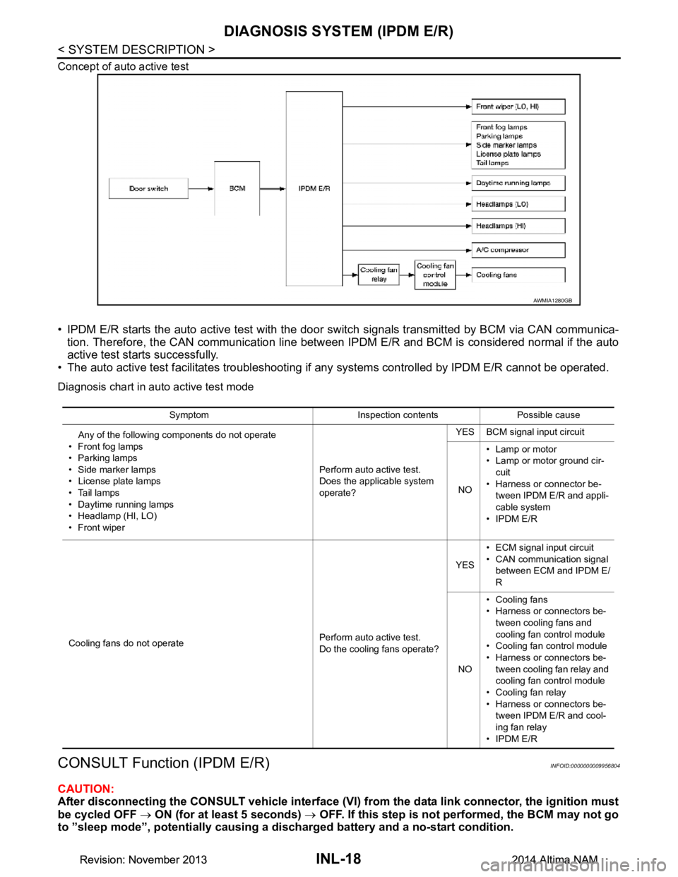
Concept of auto active test
• IPDM E/R starts the auto active test with the door switch signals transmitted by BCM via CAN communica-
tion. Therefore, the CAN communication line between IPDM E/R and BCM is considered normal if the auto
active test starts successfully.
• The auto active test facilitates troubleshooting if any systems controlled by IPDM E/R cannot be operated.
Diagnosis chart in auto active test mode
CONSULT Function (IPDM E/R)INFOID:0000000009956804
CAUTION:
After disconnecting the CONSULT vehicle interface (VI) from the data link connector, the ignition must
be cycled OFF → ON (for at least 5 seconds) → OFF. If this step is not performed, the BCM may not go
to ”sleep mode”, potentially causing a di scharged battery and a no-start condition.
AWMIA1280GB
Symptom Inspection contents Possible cause
Any of the following components do not operate
•Front fog lamps
• Parking lamps
• Side marker lamps
• License plate lamps
•Tail lamps
• Daytime running lamps
• Headlamp (HI, LO)
• Front wiper Perform auto active test.
Does the applicable system
operate? YES BCM signal input circuit
NO • Lamp or motor
• Lamp or motor ground cir-
cuit
• Harness or connector be- tween IPDM E/R and appli-
cable system
•IPDM E/R
Cooling fans do not operate Perform auto active test.
Do the cooling fans operate? YES
• ECM signal input circuit
• CAN communication signal between ECM and IPDM E/
R
NO • Cooling fans
• Harness or connectors be-
tween cooling fans and
cooling fan control module
• Cooling fan control module
• Harness or connectors be- tween cooling fan relay and
cooling fan control module
• Cooling fan relay
• Harness or connectors be- tween IPDM E/R and cool-
ing fan relay
•IPDM E/R
Revision: November 20132014 Altima NAMRevision: November 20132014 Altima NAM
Page 2961 of 4801
![NISSAN TEANA 2014 Service Manual
LAN-12
< SYSTEM DESCRIPTION >[CAN FUNDAMENTAL]
TROUBLE DIAGNOSIS
Symptom When Error Occurs in CAN Communication System
INFOID:0000000009461397
In CAN communication system, multiple control units mut NISSAN TEANA 2014 Service Manual
LAN-12
< SYSTEM DESCRIPTION >[CAN FUNDAMENTAL]
TROUBLE DIAGNOSIS
Symptom When Error Occurs in CAN Communication System
INFOID:0000000009461397
In CAN communication system, multiple control units mut](/manual-img/5/57390/w960_57390-2960.png)
LAN-12
< SYSTEM DESCRIPTION >[CAN FUNDAMENTAL]
TROUBLE DIAGNOSIS
Symptom When Error Occurs in CAN Communication System
INFOID:0000000009461397
In CAN communication system, multiple control units mutually transmit and receive signals. Each control unit
cannot transmit and receive signals if any error occurs on CAN communication line. Under this condition, mul-
tiple control units related to the root cause malfunction or go into fail-safe mode.
ERROR EXAMPLE
NOTE:
Each vehicle differs in symptom of each control unit under fail-safe mode and CAN communication line wiring.
Example: Main Line Between Data Link Connector and ABS Actuator and Electric Un it (Control Unit) Open Circuit
JSMIA0442GB
Unit name Major symptom
ECM Engine torque limiting is affected, and shift harshness increases.
BCM • Reverse warning buzzer does not sound.
• The front wiper moves under continuous operation mode even though the front wip- er switch being in the intermittent position.
EPS control unit The steeri ng effort increases.
Combination meter • The shift position indicator and OD OFF indicator turn OFF.
• The speedometer is inoperative.
• The odo/trip meter stops.
ABS actuator and electric unit (control unit) Normal operation.
TCM No impact on operation.
IPDM E/R When the ignition switch is ON,
• The headlamps (Lo) turn ON.
• The cooling fan continues to rotate.
Revision: November 20132014 Altima NAMRevision: November 20132014 Altima NAM
Page 2963 of 4801
![NISSAN TEANA 2014 Service Manual
LAN-14
< SYSTEM DESCRIPTION >[CAN FUNDAMENTAL]
TROUBLE DIAGNOSIS
NOTE:
When data link connector branch line is open, transmiss ion and reception of CAN communication signals are
not affected. Theref NISSAN TEANA 2014 Service Manual
LAN-14
< SYSTEM DESCRIPTION >[CAN FUNDAMENTAL]
TROUBLE DIAGNOSIS
NOTE:
When data link connector branch line is open, transmiss ion and reception of CAN communication signals are
not affected. Theref](/manual-img/5/57390/w960_57390-2962.png)
LAN-14
< SYSTEM DESCRIPTION >[CAN FUNDAMENTAL]
TROUBLE DIAGNOSIS
NOTE:
When data link connector branch line is open, transmiss ion and reception of CAN communication signals are
not affected. Therefore, no symptoms occur. However, be sure to repair malfunctioning circuit.
Example: CAN-H, CAN-L Harness Short Circuit
CAN Diagnosis with CONSULTINFOID:0000000009461398
CAN diagnosis on CONSULT extracts the root c ause by receiving the following information.
Unit name Major symptom
ECM
Normal operation.
BCM
EPS control unit
Combination meter
ABS actuator and electric unit (control unit)
TCM
IPDM E/R
JSMIA0445GB
Unit name Major symptom
ECM • Engine torque limiting is affected, and shift harshness increases.
• Engine speed drops.
BCM • Reverse warning buzzer does not sound.
• The front wiper moves under continuous operation mode even though the front wiper switch being in the intermittent position.
• The room lamp does not turn ON.
• The engine does not start (if an error or malfunction occurs while turning the igni- tion switch OFF.)
• The steering lock does not release (if an error or malfunction occurs while turning the ignition switch OFF.)
EPS control unit The steeri ng effort increases.
Combination meter • The tachometer and the speedometer do not move.
• Warning lamps turn ON.
• Indicator lamps do not turn ON.
ABS actuator and electric unit (control unit) Normal operation.
TCM No impact on operation.
IPDM E/R When the ignition switch is ON,
• The headlamps (Lo) turn ON.
• The cooling fan continues to rotate.
Revision: November 20132014 Altima NAMRevision: November 20132014 Altima NAM
Page 3189 of 4801

GENERAL MAINTENANCEMA-5
< PERIODIC MAINTENANCE >
C
D E
F
G H
I
J
K L
M B
MA
N
O A
PERIODIC MAINTENANCE
GENERAL MAINTENANCE
FOR USA AND CANADA
FOR USA AND CANADA : Explana
tion of General MaintenanceINFOID:0000000009464530
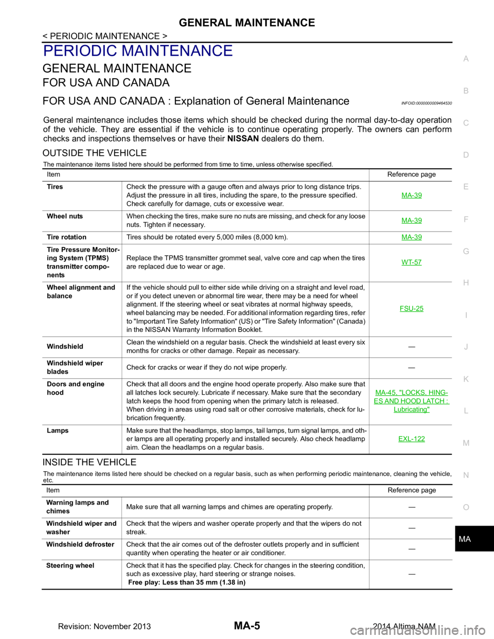
General maintenance includes those items which shoul d be checked during the normal day-to-day operation
of the vehicle. They are essential if the vehicle is to continue operating properly. The owners can perform
checks and inspections themselves or have their NISSAN dealers do them.
OUTSIDE THE VEHICLE
The maintenance items listed here should be performed from time to time, unless otherwise specified.
INSIDE THE VEHICLE
The maintenance items listed here should be checked on a regular basis, such as when performing periodic maintenance, cleaning the vehicle,
etc.
Item Reference page
Tires Check the pressure with a gauge often and always prior to long distance trips.
Adjust the pressure in all tires, including the spare, to the pressure specified.
Check carefully for damage, cuts or excessive wear. MA-39
Wheel nuts
When checking the tires, make sure no nuts are missing, and check for any loose
nuts. Tighten if necessary. MA-39
Tire rotation
Tires should be rotated every 5,000 miles (8,000 km). MA-39
Tire Pressure Monitor-
ing System (TPMS)
transmitter compo-
nents Replace the TPMS transmitter grommet seal, valve core and cap when the tires
are replaced due to wear or age. WT-57
Wheel alignment and
balance If the vehicle should pull to either side while driving on a straight and level road,
or if you detect uneven or abnormal tire wear, there may be a need for wheel
alignment. If the steering wheel or seat vibrates at normal highway speeds,
wheel balancing may be needed. For additional information regarding tires, refer
to "Important Tire Safety Information" (US) or "Tire Safety Information" (Canada)
in the NISSAN Warranty Information Booklet. FSU-25
Windshield
Clean the windshield on a regular basis. Check the windshield at least every six
months for cracks or other damage. Repair as necessary. —
Windshield wiper
blades Check for cracks or wear if they do not wipe properly. —
Doors and engine
hood Check that all doors and the engine hood operate properly. Also make sure that
all latches lock securely. Lubricate if necessary. Make sure that the secondary
latch keeps the hood from opening when the primary latch is released.
When driving in areas using road salt or other corrosive materials, check for lu-
brication frequently. MA-45, "LOCKS, HING-
ES AND HOOD LATCH :
Lubricating"
Lamps
Make sure that the headlamps, stop lamps, tail lamps, turn signal lamps, and oth-
er lamps are all operating properly and installed securely. Also check headlamp
aim. Clean the headlamps on a regular basis. EXL-122
Item
Reference page
Warning lamps and
chimes Make sure that all warning lamps and chimes are operating properly. —
Windshield wiper and
washer Check that the wipers and washer operate properly and that the wipers do not
streak. —
Windshield defroster Check that the air comes out of the defroster outlets properly and in sufficient
quantity when operating the heater or air conditioner. —
Steering wheel Check that it has the specified play. Check for changes in the steering condition,
such as excessive play, hard steering or strange noises.
Free play: Less than 35 mm (1.38 in) —
Revision: November 20132014 Altima NAM
Page 3355 of 4801
![NISSAN TEANA 2014 Service Manual
PC S-6
< SYSTEM DESCRIPTION >[IPDM E/R]
SYSTEM
RELAY CONTROL SYSTEM : System Description
INFOID:0000000009461598
IPDM E/R activates the internal cont rol circuit to perform the relay ON-OFF control a NISSAN TEANA 2014 Service Manual
PC S-6
< SYSTEM DESCRIPTION >[IPDM E/R]
SYSTEM
RELAY CONTROL SYSTEM : System Description
INFOID:0000000009461598
IPDM E/R activates the internal cont rol circuit to perform the relay ON-OFF control a](/manual-img/5/57390/w960_57390-3354.png)
PC S-6
< SYSTEM DESCRIPTION >[IPDM E/R]
SYSTEM
RELAY CONTROL SYSTEM : System Description
INFOID:0000000009461598
IPDM E/R activates the internal cont rol circuit to perform the relay ON-OFF control according to the input sig-
nals from various sensors and the request signals received from control units via CAN communication.
CAUTION:
IPDM E/R integrated relays cannot be removed.
POWER CONSUMPTION CONTROL SYSTEM
Control relay Input/output T ransmit unitControl partReference
page
Front fog lamp relay Front fog lamp request signal BCM (CAN) Front fog lamp EXL-101
Headlamp high relay High beam request signal BCM (CAN) Headlamp highEXL-91
Headlamp low relay Low beam request signal BCM (CAN) Headlamp lowEXL-93
(halogen)
EXL-94
(xe-
non)
Tail lamp relay Position light request signal BCM (CAN) •Parking lamp
• Side marker lamp
• License plate lamp
•Tail lamp EXL-103
• Front wiper relay
• Front wiper high relay Front wiper request signal BCM (CAN)
Front wiperWW-48
Front wiper auto stop signal Front wiper motor
Cooling fan relay-1 Cooling fan request signal ECM Cooling fan EC-499
(QR25DE)
EC-953
(VQ35DE)
A/C relay A/C compressor request signal ECM (CAN) A/C compressor HAC-87
(automatic
air condi-
tioner)
HAC-151
(manual air
conditioner)
Ignition relay-1 Ignition switch ON signal BCM (CAN)
Ignition relay-1PCS-58
Vehicle speed signal Combination meter (CAN)
Push-button ignition switch Push-button ignition switch
Fuel pump relay Fuel pump request signal ECM Fuel pump EC-508
(QR25DE)
EC-965
(VQ35DE)
ECM relay ECM relay cont rol signal ECM ECM relay EC-203
(QR25DE)
EC-709
(VQ35DE)
Throttle contro l motor relay Throttle control
motor relay sig-
nal ECMThrottle control motor re-
lay EC-475
(QR25DE)
EC-933
(VQ35DE)
Starter relay Starter relay control signal BCM Starter motor PCS-12
Starter control relay
Revision: November 20132014 Altima NAMRevision: November 20132014 Altima NAM