Page 3342 of 4801

PB-4
< BASIC INSPECTION >
PARKING BRAKE SYSTEM
BASIC INSPECTION
PARKING BRAKE SYSTEM
InspectionINFOID:0000000009462912
PEDAL STROKE
1. Operate parking brake pedal with a force of 196 N (20.0 kg-f, 44.1 lb-f), make sure pedal stroke is within
the specified number of notches. (Check it by listening and counting ratchet clicks.)
2. When brake warning lamp turns ON, check that the pedal stroke is within the specified number of notches. (Check it by listening to the clicks of the ratchet.)
INSPECT COMPONENTS
• Make sure that the mounting conditions (loosenes s, backlash, etc.) of each component are normal.
• Check the following:
- Device assembly for bend, damage and cracks. Replace if necessary.
- Cables and equalizer for wear and damage. Replace if necessary.
- Parking brake switch. Replace if necessary.
AdjustmentINFOID:0000000009462913
ADJUSTMENT
1. Remove rear wheel and tire using power tool. Refer to WT-55, "Adjustment".
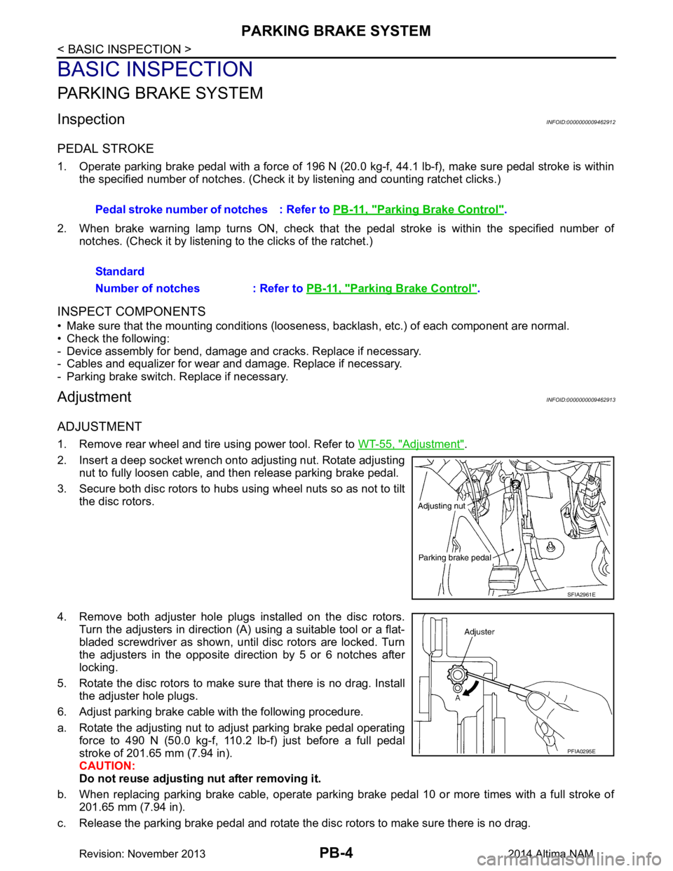
2. Insert a deep socket wrench onto adjusting nut. Rotate adjusting nut to fully loosen cable, and then release parking brake pedal.
3. Secure both disc rotors to hubs using wheel nuts so as not to tilt the disc rotors.
4. Remove both adjuster hole plugs installed on the disc rotors. Turn the adjusters in direction (A) using a suitable tool or a flat-
bladed screwdriver as shown, until disc rotors are locked. Turn
the adjusters in the opposite direction by 5 or 6 notches after
locking.
5. Rotate the disc rotors to make sure that there is no drag. Install the adjuster hole plugs.
6. Adjust parking brake cable with the following procedure.
a. Rotate the adjusting nut to adjust parking brake pedal operating force to 490 N (50.0 kg-f, 110.2 lb-f) just before a full pedal
stroke of 201.65 mm (7.94 in).
CAUTION:
Do not reuse adjusting nut after removing it.
b. When replacing parking brake cable, operate parking brake pedal 10 or more times with a full stroke of 201.65 mm (7.94 in).
c. Release the parking brake pedal and rotate the disc rotors to make sure there is no drag. Pedal stroke number of notches : Refer to
PB-11, "Parking Brake Control"
.
Standard
Number of notches : Refer to PB-11, "Parking Brake Control"
.
SFIA2961E
PFIA0295E
Revision: November 20132014 Altima NAM
Page 3343 of 4801

PARKING BRAKE SYSTEMPB-5
< BASIC INSPECTION >
C
D E
G H
I
J
K L
M A
B
PB
N
O P
d. Rotate the adjusting nut to adjust the parking brak e pedal force to 196 N (20.0 kg-f, 44.1 lb-f) when the
parking brake pedal stroke is within the specified number of notches. (check it by listening and counting
the ratchet clicks).
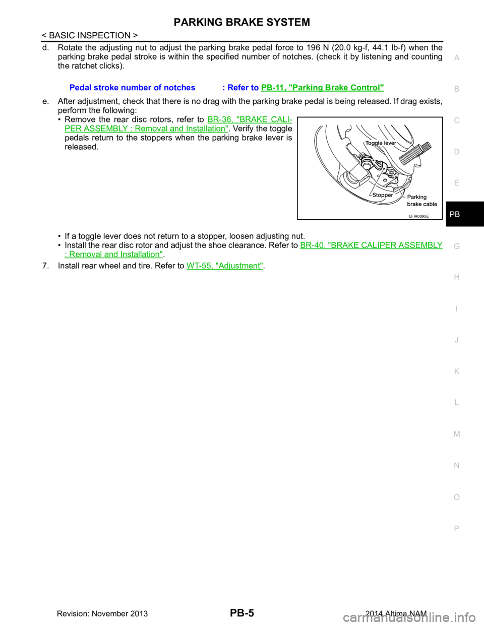
e. After adjustment, check that there is no drag with the parking brake pedal is being released. If drag exists,
perform the following:
• Remove the rear disc rotors, refer to BR-36, "BRAKE CALI-
PER ASSEMBLY : Removal and Installation". Verify the toggle
pedals return to the stoppers when the parking brake lever is
released.
• If a toggle lever does not return to a stopper, loosen adjusting nut.
• Install the rear disc rotor and adjust the shoe clearance. Refer to BR-40, "BRAKE CALIPER ASSEMBLY
: Removal and Installation".
7. Install rear wheel and tire. Refer to WT-55, "Adjustment"
.
Pedal stroke number of notches : Refer to
PB-11, "Parking Brake Control"
LFIA0095E
Revision: November 20132014 Altima NAM
Page 3344 of 4801

PB-6
< BASIC INSPECTION >
PARKING BRAKE SHOE
PARKING BRAKE SHOE
InspectionINFOID:0000000009462914
LINING THICKNESS INSPECTION
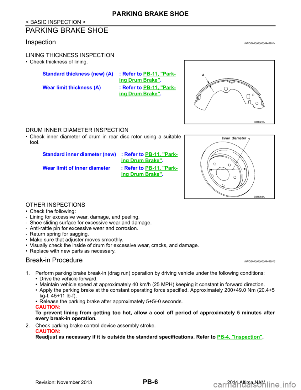
• Check thickness of lining.
DRUM INNER DIAMETER INSPECTION
• Check inner diameter of drum in rear disc rotor using a suitabletool.
OTHER INSPECTIONS
• Check the following:
- Lining for excessive wear, damage, and peeling.
- Shoe sliding surface for excessive wear and damage.
- Anti-rattle pin for excessive wear and corrosion.
- Return spring for sagging.
• Make sure that adjuster moves smoothly.
• Visually check the inside of drum for excessive wear, cracks, and damage.
• Replace with new parts as necessary.
Break-in ProcedureINFOID:0000000009462915
1. Perform parking brake break-in (drag run) operation by driving vehicle under the following conditions: • Drive the vehicle forward.
• Maintain vehicle speed at approximately 40 km/h (25 MPH) keeping it constant in forward direction.
• Apply the parking brake at the constant operating force specified. Approximately 200+49.0 Nm (20.4+5
kg-f, 45+11 lb-f).
• Release the parking brake after approximately 5+5/-0 seconds.
CAUTION:
To prevent lining from getting t oo hot, allow a cool off period of approximately 5 minutes after
every break-in operation.
2. Check parking brake control device assembly stroke. CAUTION:
Readjust as necessary if it is outside the standard specifications. Refer to PB-4, "Inspection"
.
Standard thickness (new) (A) : Refer to
PB-11, "Park-
ing Drum Brake".
Wear limit thickness (A) : Refer to PB-11, "Park-
ing Drum Brake".
SBR021A
Standard inner diameter (new) : Refer to PB-11, "Park-
ing Drum Brake".
Wear limit of inner diameter : Refer to PB-11, "Park-
ing Drum Brake".
SBR768A
Revision: November 20132014 Altima NAM
Page 3346 of 4801

PB-8
< REMOVAL AND INSTALLATION >
PARKING BRAKE CONTROL
3. Disconnect the harness connector from the parking brake switch and remove parking brake switch.
4. Remove adjusting nut and discard, then loosen front cable. CAUTION:
Do not reuse adjusting nut.
5. Disconnect front cable.
6. Remove parking brake pedal assembly nuts and remove parking brake pedal assembly.
7. Remove ITS control unit. Refer to AV-436, "Removal and Installation"
.
8. Remove spring and separate rear cables (LH/ RH) from front cable, remove front cable.
9. Remove rear brake caliper and disc brake rotor. Refer to BR-40, "BRAKE CALIPER ASSEMBLY :
Removal and Installation".
10. Remove parking brake shoe, and remove r ear cable from toggle lever. Refer to IP-14, "Exploded View"
.
11. Remove rear cable bolts and nuts, then remove rear cables.
INSTALLATION
Installation is in the reverse order of removal.
• Adjust the parking brake with new adjusting nut. Refer to WT-55, "Adjustment"
.
CAUTION:
• Do not reuse adjusting nut.
• The cables should be free from twists, damage, cracks or corrosion.
Revision: November 20132014 Altima NAM
Page 3347 of 4801

PARKING BRAKE SHOEPB-9
< REMOVAL AND INSTALLATION >
C
D E
G H
I
J
K L
M A
B
PB
N
O P
PARKING BRAKE SHOE
Exploded ViewINFOID:0000000009462918
Removal and InstallationINFOID:0000000009462919
WARNING:
• Clean brakes with a vacuum dust co llector to minimize the hazard of air borne particles or other
materials.
• Clean dust on disc brake rotor and back plate usin g a vacuum dust collector. Do not blow with com-
pressed air.
CAUTION:
Put matching marks on both disc brake rotor and wheel hub when removing disc rotor.
REMOVAL
1. Remove rear wheel and tire using power tool. Refer to WT-55, "Adjustment".
2. Remove rear brake caliper and disc brake rotor. Refer to BR-40, "BRAKE CALIPER ASSEMBLY :
Removal and Installation".
3. If disc brake rotor cannot be removed, remove as follows:
a. Secure the disc brake rotor in place with wheel nuts and remove adjuster hole plug.
b. Rotate adjuster in direction (B) to retract and loosen brake shoe, using tool as shown.
c. Remove disc brake rotor.
4. Remove anti-rattle pins, retainers, anti-rattle springs, and return springs.
5. Remove parking brake shoes, adjuster assembly, and toggle lever.
INSTALLATION
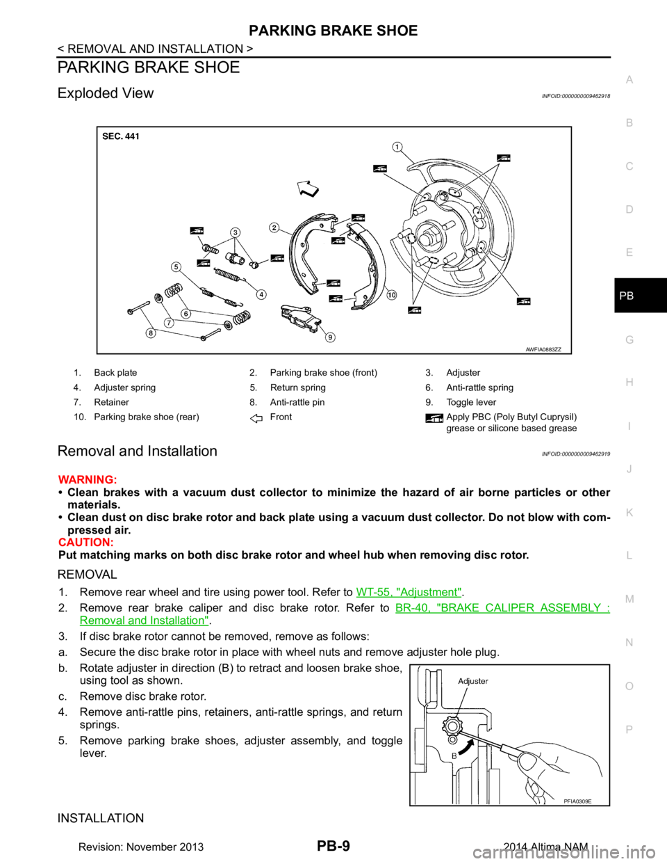
1. Back plate 2. Parking brake shoe (front) 3. Adjuster
4. Adjuster spring 5. Return spring 6. Anti-rattle spring
7. Retainer 8. Anti-rattle pin 9. Toggle lever
10. Parking brake shoe (rear) Front Apply PBC (Poly Butyl Cuprysil) grease or silicone based grease
AWFIA0883ZZ
PFIA0309E
Revision: November 20132014 Altima NAM
Page 3348 of 4801
PB-10
< REMOVAL AND INSTALLATION >
PARKING BRAKE SHOE
Installation is in the reverse order of removal. Note the following.
• Apply PBC (Poly Butyl Cuprysil) grease or silicone-based grease to the specified points during assembly.
• Assemble adjusters so that threaded part is expanded when rotat-
ing it in the direction shown.
• Shorten adjuster by rotating it as shown.
• Check shoe sliding surface and drum inner surface for grease. Wipe it off if it adhere on the surfaces.
• Perform break-in operation after replacing brake shoes or disc
rotors, or if brakes do not function well. Refer to PB-6, "Break-in
Procedure".
• Adjust parking brake pedal assembly stroke to the specified amount. Refer to PB-11, "Parking Brake Control"
.SFIA2426E
Revision: November 20132014 Altima NAM
Page 3662 of 4801
WHEEL HUBRAX-5
< PERIODIC MAINTENANCE >
CEF
G H
I
J
K L
M A
B
RAX
N
O P
PERIODIC MAINTENANCE
WHEEL HUB
On-vehicle ServiceINFOID:0000000009460676
Check axle and suspension parts for excessive play, wear or damage.
• Shake each rear wheel to check for excessive play.
Wheel Hub Bearing
If the following conditions are not met or not with in specification, replace the wheel hub and bearing.
• Check that wheel hub and bearing rotates smoothly.
• Check wheel hub and bearing axial end play.
• Check wheel hub and bearing runout. NOTE:
• Make sure the area between the disc brake rotor and wheel hub
and bearing are free from dirt or debris.
• Place the dial gauge on smooth su rface, free from scratches or
dents.
• Make sure the disc brake rotor is securely fastened to the wheel hub and bearing.
SMA525A
Axial end play : Refer to RAX-8, "Wheel
Hub Bearing".
Runout : Refer to RAX-8, "Wheel
Hub Bearing".
ALEIA0153ZZ
Revision: November 20132014 Altima NAM
Page 3663 of 4801
RAX-6
< REMOVAL AND INSTALLATION >
WHEEL HUB
REMOVAL AND INSTALLATION
WHEEL HUB
Exploded ViewINFOID:0000000009460677
Removal and InstallationINFOID:0000000009460678
REMOVAL
1. Remove the rear wheel and tire using power tool. Refer to WT-55, "Adjustment".
2. Remove brake caliper torque member bolts, leaving brake hose attached, reposition the caliper aside with
wire. Refer to BR-39, "BRAKE CALIPER AS SEMBLY : Exploded View"
.
CAUTION:
Do not depress brake pedal while caliper assembly is removed.
3. Put alignment marks on the disc brake rotor and rear wheel hub and bearing, then remove the disc rotor.
4. Remove the rear wheel sensor (1) from the knuckle and position
it aside.
1. Wheel hub and bearing assembly 2. Baffle plate 3. Knuckle
4. Rear wheel sensor Front
AWDIA1001GB
ALEIA0154ZZ
Revision: November 20132014 Altima NAM