2014 NISSAN TEANA brake rotor
[x] Cancel search: brake rotorPage 2512 of 4801
TRANSVERSE LINKFSU-11
< REMOVAL AND INSTALLATION >
C
D
F
G H
I
J
K L
M A
B
FSU
N
O P
TRANSVERSE LINK
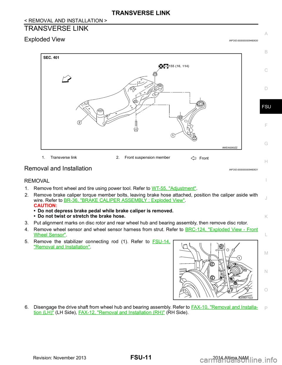
Exploded ViewINFOID:0000000009460630
Removal and InstallationINFOID:0000000009460631
REMOVAL
1. Remove front wheel and tire using power tool. Refer to WT-55, "Adjustment".
2. Remove brake caliper torque member bolts, leaving brake hose attached, position the caliper aside with
wire. Refer to BR-36, "BRAKE CALIPER ASSEMBLY : Exploded View"
.
CAUTION:
• Do not depress brake pedal while brake caliper is removed.
• Do not twist or stretch the brake hose.
3. Put alignment marks on disc rotor and rear wheel hub and bearing assembly, then remove disc rotor.
4. Remove wheel sensor and wheel sensor harness from strut. Refer to BRC-124, "Exploded View - Front
Wheel Sensor".
5. Remove the stabilizer connecting rod (1). Refer to FSU-14,
"Removal and Installation".
6. Disengage the drive shaft from wheel hub and bearing assembly. Refer to FAX-10, "Removal and Installa-
tion (LH)" (LH Side), FAX-12, "Removal and Installation (RH)" (RH Side).
1. Transverse link 2. Front suspension member
Front
AWEIA0263ZZ
ALEIA0172ZZ
Revision: November 20132014 Altima NAM
Page 2518 of 4801
STEERING KNUCKLEFSU-17
< REMOVAL AND INSTALLATION >
C
D
F
G H
I
J
K L
M A
B
FSU
N
O P
STEERING KNUCKLE
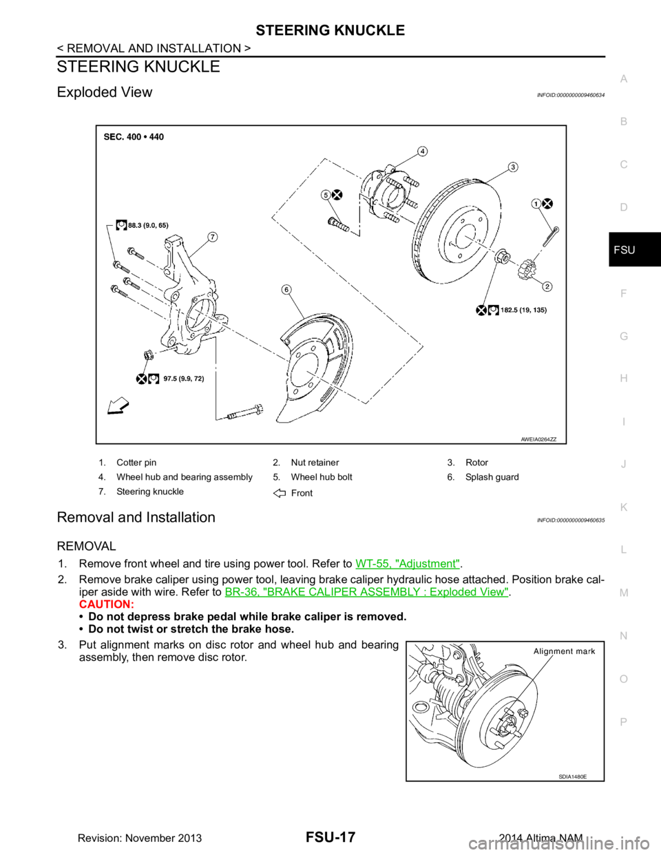
Exploded ViewINFOID:0000000009460634
Removal and InstallationINFOID:0000000009460635
REMOVAL
1. Remove front wheel and tire using power tool. Refer to WT-55, "Adjustment".
2. Remove brake caliper using power tool, leaving brak e caliper hydraulic hose attached. Position brake cal-
iper aside with wire. Refer to BR-36, "BRAKE CALIPER ASSEMBLY : Exploded View"
.
CAUTION:
• Do not depress brake pedal while brake caliper is removed.
• Do not twist or stretch the brake hose.
3. Put alignment marks on disc rotor and wheel hub and bearing assembly, then remove disc rotor.
1. Cotter pin 2. Nut retainer 3. Rotor
4. Wheel hub and bearing assembly 5. Wheel hub bolt 6. Splash guard
7. Steering knuckle Front
AWEIA0264ZZ
SDIA1480E
Revision: November 20132014 Altima NAM
Page 2521 of 4801
FSU-20
< UNIT REMOVAL AND INSTALLATION >
FRONT SUSPENSION ASSEMBLY
Removal and Installation
INFOID:0000000009460637
QR25DE ENGINE
Removal
1. Remove front wheel and tire using power tool. Refer to WT-55, "Adjustment".
2. Remove each brake caliper using power tool, leaving brake caliper hydraulic hose attached. Position each brake caliper aside with wire. Refer to BR-36, "BRAKE CALIPER ASSEMBLY : Exploded View"
.
CAUTION:
• Do not depress brake pedal while brake caliper is removed.
• Do not twist or stretch the brake hose.
3. Put alignment marks on each disc rotor and each wheel hub and bearing assembly.
4. Remove each disc rotor.
5. Remove each wheel sensor bolt (A) and each wheel sensor from each steering knuckle. Refer to BRC-124, "Removal and
Installation - Front Wheel Sensor".
CAUTION:
Do not pull on wheel sensor harness.
6. Remove stabilizer connecting rods from stabilizer bar.
7. Remove front exhaust tube. Refer to EX-5, "Exploded View"
.
8. Remove steering gear bolts. Remove steering gear from suspension member and support the steering gear with wire. Refer to ST-36, "Exploded View"
.
9. Remove engine side under cover. Refer to EM-28, "Exploded View"
.
10. Remove engine under cover. Refer to EM-28, "Exploded View"
.
11. Remove transverse link bolts and nuts. Using Tool, separate each transverse link from steering knuckles.
12. Remove rear engine mount torque rod bolt and rear torque rod insulator bracket, then remove support bracket. Refer to EM-83, "Exploded View"
.
13. Position the power steering lines aside and remove the power steering line clips.
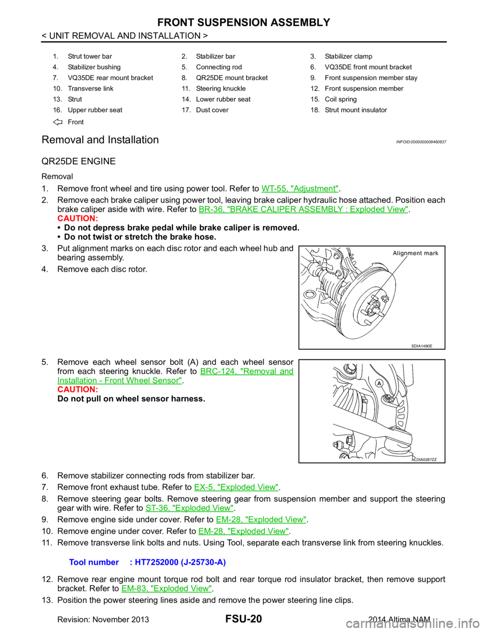
1. Strut tower bar 2. Stabilizer bar 3. Stabilizer clamp
4. Stabilizer bushing 5. Connecting rod 6. VQ35DE front mount bracket
7. VQ35DE rear mount bracket 8. QR25DE mount bracket 9. Front suspension member stay
10. Transverse link 11. Steering knuckle 12. Front suspension member
13. Strut 14. Lower rubber seat 15. Coil spring
16. Upper rubber seat 17. Dust cover 18. Strut mount insulator
Front
SDIA1480E
ALDIA0287ZZ
Tool number : HT7252000 (J-25730-A)
Revision: November 20132014 Altima NAM
Page 3186 of 4801

MA-2
OIL FILTER : Removal and Installation ..................27
SPARK PLUG ........................................................ ...28
SPARK PLUG : Removal and Installation ..............29
EVAP VAPOR LINES ............................................. ...30
EVAP VAPOR LINES : Inspection ..........................30
CHASSIS AND BODY MAINTENANCE ......... ...31
IN-CABIN MICROFILTER ...................................... ...31
IN-CABIN MICROFILTER : Removal and Installa-
tion ....................................................................... ...
31
EXHAUST SYSTEM ............................................... ...31
EXHAUST SYSTEM : Checking Exhaust System ...31
CVT FLUID ............................................................. ...31
CVT FLUID : RE0F10D ..........................................32
CVT FLUID : Inspection ..........................................32
CVT FLUID : Replacement .....................................32
CVT FLUID : Adjustment ........................................34
CVT FLUID : RE0F10E ..........................................35
CVT FLUID : Inspection ..........................................35
CVT FLUID : Replacement .....................................35
CVT FLUID : Adjustment ........................................37
WHEELS ................................................................ ...38
WHEELS : Inspection .............................................38
WHEELS : Adjustment ...........................................39
BRAKE FLUID LEVEL AND LEAKS ........................40
BRAKE FLUID LEVEL AND LEAKS : Inspection ...40
BRAKE LINES AND CABLES ............................... ...41
BRAKE LINES AND CABLES : Inspection .............41
BRAKE FLUID ........................................................ ...41
BRAKE FLUID : Drain and Refill .............................41
DISC BRAKE .......................................................... ...42
DISC BRAKE : Front Brake Pad .............................42
DISC BRAKE : Inspection .......................................42
DISC BRAKE : Front Brake Rotor ...........................42
DISC BRAKE : Inspection .......................................42
DISC BRAKE : Rear Brake Pad ..............................43
DISC BRAKE : Inspection .......................................43
DISC BRAKE : Rear Brake Rotor ...........................43
DISC BRAKE : Inspection .......................................43
STEERING GEAR AND LINKAGE ........................ ...43
STEERING GEAR AND LINKAGE : Inspection ......43
POWER STEERING FLUID AND LINES ............... ...43
POWER STEERING FLUID AND LINES : Inspec-
tion ....................................................................... ...
44
AXLE AND SUSPENSION PARTS ........................ ...44
AXLE AND SUSPENSION PARTS : Inspection .....44
DRIVE SHAFT ........................................................ ...45
DRIVE SHAFT : Inspection .....................................45
LOCKS, HINGES AND HOOD LATCH .................. ...45
LOCKS, HINGES AND HOOD LATCH : Lubricat-
ing ........................................................................ ...
45
SEAT BELT, BUCKLES, RETRACTORS, AN-
CHORS AND ADJUSTERS ................................... ...
45
SEAT BELT, BUCKLES, RETRACTORS, AN-
CHORS AND ADJUSTERS : Inspection .............. ...
45
Revision: November 20132014 Altima NAM
Page 3224 of 4801
MA-40
< PERIODIC MAINTENANCE >
CHASSIS AND BODY MAINTENANCE
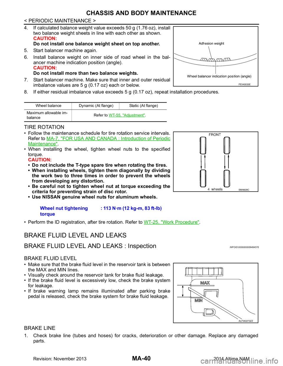
4. If calculated balance weight value exceeds 50 g (1.76 oz), installtwo balance weight sheets in line with each other as shown.
CAUTION:
Do not install one balance weight sheet on top another.
5. Start balancer machine again.
6. Install balance weight on inner side of road wheel in the bal- ancer machine indication position (angle).
CAUTION:
Do not install more than two balance weights.
7. Start balancer machine. Make sure that inner and outer residual imbalance values are 5 g (0.17 oz) each or below.
8. If either residual imbalance value exceeds 5 g (0.17 oz), repeat installation procedures.
TIRE ROTATION
• Follow the maintenance schedule for tire rotation service intervals.
Refer to MA-7, "FOR USA AND CANADA : Introduction of Periodic
Maintenance".
• When installing the wheel, tighten wheel nuts to the specified torque.
CAUTION:
• Do not include the T-type spare tire when rotating the tires.
• When installing wheels, tighten them diagonally by dividing
the work two to three times in order to prevent the wheels
from developing any distortion.
• Be careful not to tighten wheel nut at torque exceeding the criteria for preventing strain of disc rotor.
• Use NISSAN genuine wheel nuts for aluminum wheels.
• Perform the ID registration, after tire rotation. Refer to WT-25, "Work Procedure"
.
BRAKE FLUID LEVEL AND LEAKS
BRAKE FLUID LEVEL AND LEAKS : InspectionINFOID:0000000009464576
BRAKE FLUID LEVEL
• Make sure that the brake fluid level in the reservoir tank is between
the MAX and MIN lines.
• Visually check around the reservoir tank for brake fluid leakage.
• If the brake fluid level is excessively low, check the brake system for leakage.
• If brake warning lamp remains illuminated after parking brake
pedal is released, check the brake system for brake fluid leakage.
BRAKE LINE
1. Check brake line (tubes and hoses) for cracks, deterioration or other damage. Replace any damaged
parts.
Wheel balance Dynamic (At flange) Static (At flange)
Maximum allowable im-
balance Refer to
WT-55, "Adjustment"
.
PEIA0033E
Wheel nut tightening
torque : 113 N·m (12 kg-m, 83 ft-lb)
SMA829C
ALFIA0273ZZ
Revision: November 20132014 Altima NAM
Page 3226 of 4801
MA-42
< PERIODIC MAINTENANCE >
CHASSIS AND BODY MAINTENANCE
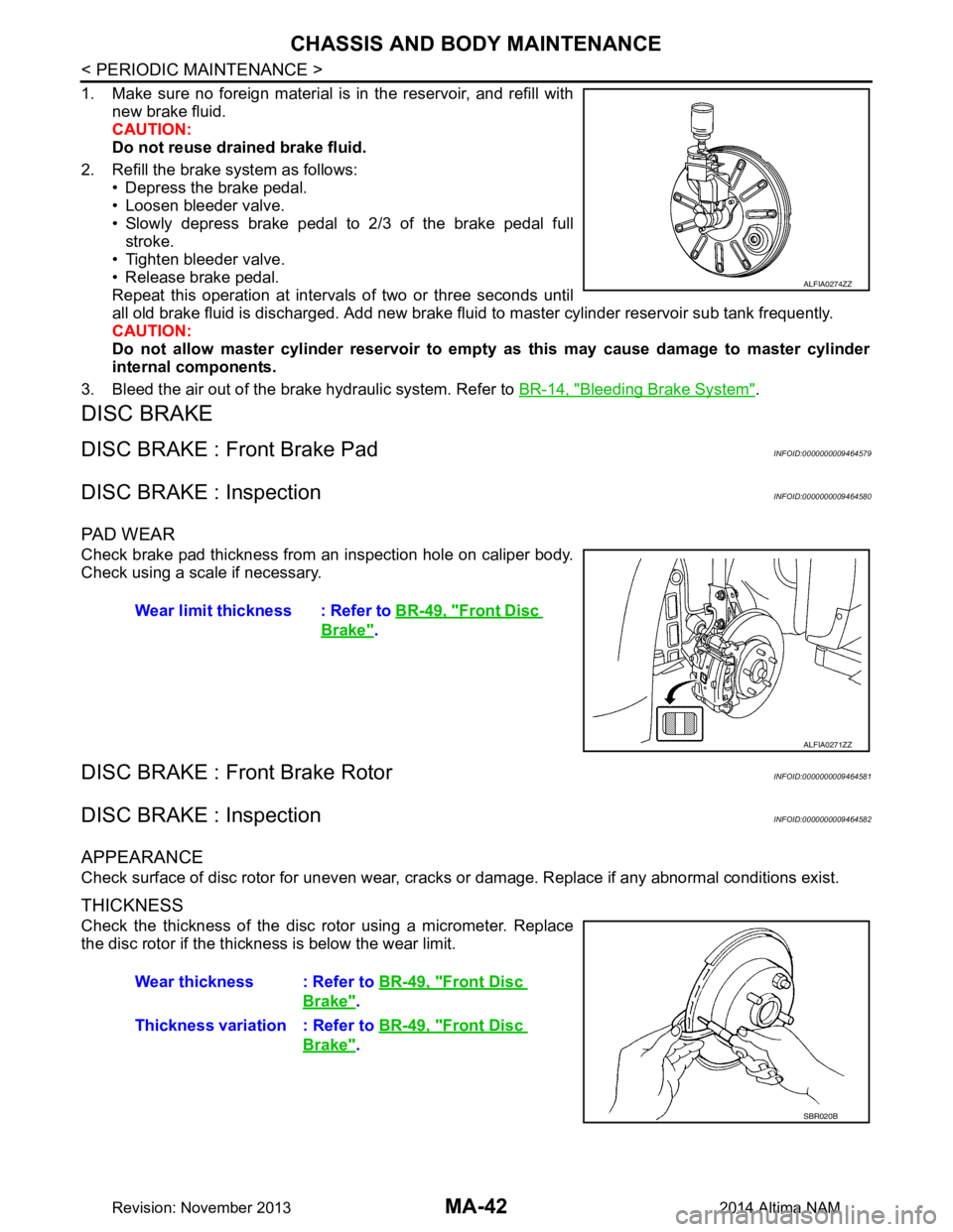
1. Make sure no foreign material is in the reservoir, and refill withnew brake fluid.
CAUTION:
Do not reuse drained brake fluid.
2. Refill the brake system as follows: • Depress the brake pedal.
• Loosen bleeder valve.
• Slowly depress brake pedal to 2/3 of the brake pedal full stroke.
• Tighten bleeder valve.
• Release brake pedal.
Repeat this operation at intervals of two or three seconds until
all old brake fluid is discharged. Add new brake flui d to master cylinder reservoir sub tank frequently.
CAUTION:
Do not allow master cylinder reservoir to empt y as this may cause damage to master cylinder
internal components.
3. Bleed the air out of the brake hydraulic system. Refer to BR-14, "Bleeding Brake System"
.
DISC BRAKE
DISC BRAKE : Front Brake PadINFOID:0000000009464579
DISC BRAKE : InspectionINFOID:0000000009464580
PA D W E A R
Check brake pad thickness from an inspection hole on caliper body.
Check using a scale if necessary.
DISC BRAKE : Front Brake RotorINFOID:0000000009464581
DISC BRAKE : InspectionINFOID:0000000009464582
APPEARANCE
Check surface of disc rotor for uneven wear, cracks or damage. Replace if any abnormal conditions exist.
THICKNESS
Check the thickness of the disc rotor using a micrometer. Replace
the disc rotor if the thickness is below the wear limit.
ALFIA0274ZZ
Wear limit thickness : Refer to BR-49, "Front Disc
Brake".
ALFIA0271ZZ
Wear thickness : Refer to BR-49, "Front Disc
Brake".
Thickness variation : Refer to BR-49, "Front Disc
Brake".
SBR020B
Revision: November 20132014 Altima NAM
Page 3227 of 4801
CHASSIS AND BODY MAINTENANCEMA-43
< PERIODIC MAINTENANCE >
C
D E
F
G H
I
J
K L
M B
MA
N
O A
DISC BRAKE : Rear Brake PadINFOID:0000000009464583
DISC BRAKE : InspectionINFOID:0000000009464584
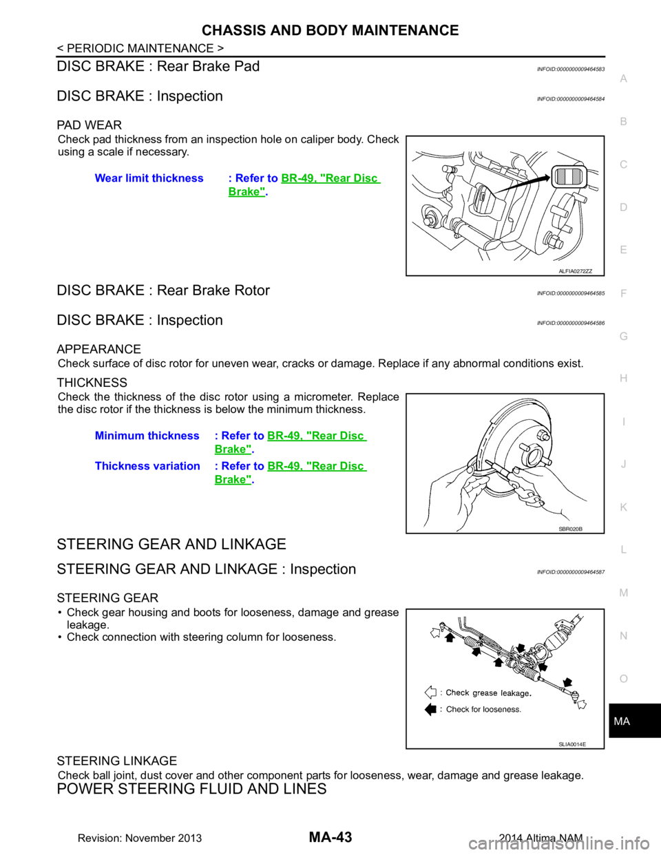
PA D W E A R
Check pad thickness from an inspection hole on caliper body. Check
using a scale if necessary.
DISC BRAKE : Rear Brake RotorINFOID:0000000009464585
DISC BRAKE : InspectionINFOID:0000000009464586
APPEARANCE
Check surface of disc rotor for uneven wear, cracks or damage. Replace if any abnormal conditions exist.
THICKNESS
Check the thickness of the disc rotor using a micrometer. Replace
the disc rotor if the thickness is below the minimum thickness.
STEERING GEAR AND LINKAGE
STEERING GEAR AND LINKAGE : InspectionINFOID:0000000009464587
STEERING GEAR
• Check gear housing and boots for looseness, damage and grease leakage.
• Check connection with steering column for looseness.
STEERING LINKAGE
Check ball joint, dust cover and other component parts for looseness, wear, damage and grease leakage.
POWER STEERING FLUID AND LINES
Wear limit thickness : Refer to BR-49, "Rear Disc
Brake".
ALFIA0272ZZ
Minimum thickness : Refer to BR-49, "Rear Disc
Brake".
Thickness variation : Refer to BR-49, "Rear Disc
Brake".
SBR020B
SLIA0014E
Revision: November 20132014 Altima NAM
Page 3341 of 4801
PREPARATIONPB-3
< PREPARATION >
C
D E
G H
I
J
K L
M A
B
PB
N
O P
PREPARATION
PREPARATION
Commercial Service ToolINFOID:0000000009462911
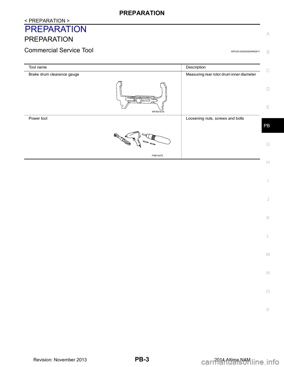
Tool name Description
Brake drum clearance gauge Measuring rear rotor drum inner diameter
Power tool Loosening nuts, screws and bolts
WFIA0167E
PIIB1407E
Revision: November 20132014 Altima NAM