2014 NISSAN TEANA brake rotor
[x] Cancel search: brake rotorPage 188 of 4801
![NISSAN TEANA 2014 Service Manual
BRC-42
< ECU DIAGNOSIS INFORMATION >[VDC/TCS/ABS]
ABS ACTUATOR AND ELECTRIC UNIT (CONTROL UNIT)
ABS FUNCTION
ABS warning lamp and SLIP indicator lamp in combi
nation meter turn ON when a malfunction NISSAN TEANA 2014 Service Manual
BRC-42
< ECU DIAGNOSIS INFORMATION >[VDC/TCS/ABS]
ABS ACTUATOR AND ELECTRIC UNIT (CONTROL UNIT)
ABS FUNCTION
ABS warning lamp and SLIP indicator lamp in combi
nation meter turn ON when a malfunction](/manual-img/5/57390/w960_57390-187.png)
BRC-42
< ECU DIAGNOSIS INFORMATION >[VDC/TCS/ABS]
ABS ACTUATOR AND ELECTRIC UNIT (CONTROL UNIT)
ABS FUNCTION
ABS warning lamp and SLIP indicator lamp in combi
nation meter turn ON when a malfunction occurs in sys-
tem [ABS actuator and electric unit (control unit)]. The control is suspended for VDC, TCS and ABS functions.
However, EBD functions operate normally.
EBD FUNCTION
ABS warning lamp, brake warning lamp and SLIP indicator lamp in combination meter turn ON when a mal-
function occurs in system [ABS ac tuator and electric unit (control unit) ]. The control is suspended for VDC,
TCS, ABS and EBD functions.
DTC Malfunction detected condition Fail-safe condition
C1101 When an open circuit is detected in rear RH wheel sensor circuit.
The following functions are sus-
pended:
•VDC
•ABS
• EBD (only when both rear wheels are malfunctioning)
C1102 When an open circuit is detected in rear LH wheel sensor circuit.
C1103 When an open circuit is detected in front RH wheel sensor circuit.
C1104 When an open circuit is detected in front LH wheel sensor circuit.
C1105 • When a short circuit is detected in rear RH wheel sensor circuit.
• When power supply voltage of rear RH wheel sensor is in following state.
- Rear RH wheel sensor power supply voltage: 7.2 V ≥ Rear RH wheel sensor pow-
er supply voltage
• When distance between rear RH wheel sensor and rear RH wheel sensor rotor is
large.
• When installation of rear RH wheel sensor or rear RH wheel sensor rotor is not normal.
C1106 • When a short circuit is detected in rear LH wheel sensor circuit.
• When power supply voltage of rear LH wheel sensor is in following state.
- Rear LH wheel sensor power supply voltage: 7.2 V ≥ Rear LH wheel sensor power
supply voltage
• When distance between rear LH wheel sensor and rear LH wheel sensor rotor is large.
• When installation of rear LH wheel sensor or rear LH wheel sensor rotor is not nor-
mal.
C1107 • When a short circuit is detected in front RH wheel sensor circuit.
• When power supply voltage of front RH wheel sensor is in following state.
- Front RH wheel sensor power supply voltage: 7.2 V ≥ Front RH wheel sensor
power supply voltage
• When distance between front RH wheel sensor and front RH wheel sensor rotor is large.
• When installation of front RH wheel sensor or front RH wheel sensor rotor is not normal.
C1108 • When a short circuit is detected in front LH wheel sensor circuit.
• When power supply voltage of front LH wheel sensor is in following state.
- Front LH wheel sensor power supply voltage: 7.2 V ≥ Front LH wheel sensor pow-
er supply voltage
• When distance between front LH wheel sensor and front LH wheel sensor rotor is large.
• When installation of front LH wheel sensor or front LH wheel sensor rotor is not normal.
C1109 • When ignition power supply voltage is in following state.
- Ignition power supply voltage: 10 V ≥ Ignition power supply voltage.
- Ignition power supply voltage: 16 V ≤ Ignition power supply voltage. The following functions are sus-
pended:
•VDC
•TCS
•ABS
•EBD
C 111 0
When there is an internal malfunction in the ABS actuator and electric unit (control
unit).
C 1111 W h e n a m a l f u n c t i o n i s d e t e c t e d i n m o t o r o r m o t o r r e l a y. The following functions are sus-
pended:
•VDC
•TCS
•ABS
Revision: November 20132014 Altima NAMRevision: November 20132014 Altima NAM
Page 262 of 4801
![NISSAN TEANA 2014 Service Manual
BRC-116
< SYMPTOM DIAGNOSIS >[VDC/TCS/ABS]
VDC/TCS/ABS
SYMPTOM DIAGNOSIS
VDC/TCS/ABS
Symptom TableINFOID:0000000009463838
If ABS warning lamp and SLIP indicator
lamp turn ON, perform self-diagnosis. NISSAN TEANA 2014 Service Manual
BRC-116
< SYMPTOM DIAGNOSIS >[VDC/TCS/ABS]
VDC/TCS/ABS
SYMPTOM DIAGNOSIS
VDC/TCS/ABS
Symptom TableINFOID:0000000009463838
If ABS warning lamp and SLIP indicator
lamp turn ON, perform self-diagnosis.](/manual-img/5/57390/w960_57390-261.png)
BRC-116
< SYMPTOM DIAGNOSIS >[VDC/TCS/ABS]
VDC/TCS/ABS
SYMPTOM DIAGNOSIS
VDC/TCS/ABS
Symptom TableINFOID:0000000009463838
If ABS warning lamp and SLIP indicator
lamp turn ON, perform self-diagnosis.
NOTE:
• 1: The ABS does not operate when the speed is 10 km/h (6 MPH) or less.
• 2: Under the following conditions, ABS is activated and vibration is felt when brake pedal is lightly depressed (just place a foot on it).
However, this is normal.
- When shifting gears
- When driving on slippery road
- During cornering at high speed
- When passing over bumps or grooves [approximately 50 mm (1.97 in) or more]
- When pulling away just after starting engine [at approximately 10 km/h (6 MPH) or higher] Symptom Check item Reference
Excessive ABS function operation fre-
quency Brake force distribution
BRC-117, "Diagno-
sis Procedure"Looseness of front and rear axle
Wheel sensor and rotor system
Unexpected pedal reaction Brake pedal stroke
BRC-118, "Diagno-
sis Procedure"Make sure the braking force is sufficient when the ABS is not operating.
The braking distance is long Check stopping distance when the ABS is not operating. BRC-119, "Diagno-
sis Procedure"
ABS function does not operate (Note 1) ABS ac
tuator and electric unit (control unit) BRC-120, "Diag-nosis Procedure"
Pedal vibration or ABS operation sound
occurs (Note 2) Brake pedal
BRC-121, "Diag-
nosis Procedure"ABS actuator and electric unit (control unit)
Vehicle jerks duri ng VDC/TCS/ABS con-
trol ABS actuator and electric unit (control unit)
BRC-122, "Diag-
nosis Procedure"TCM
ECM
Revision: November 20132014 Altima NAMRevision: November 20132014 Altima NAM
Page 263 of 4801
![NISSAN TEANA 2014 Service Manual
EXCESSIVE ABS FUNCTION OPERATION FREQUENCYBRC-117
< SYMPTOM DIAGNOSIS > [VDC/TCS/ABS]
C
D E
G H
I
J
K L
M A
B
BRC
N
O P
EXCESSIVE ABS FUNCTION OPERATION FREQUENCY
Diagnosis ProcedureINFOID:0000000 NISSAN TEANA 2014 Service Manual
EXCESSIVE ABS FUNCTION OPERATION FREQUENCYBRC-117
< SYMPTOM DIAGNOSIS > [VDC/TCS/ABS]
C
D E
G H
I
J
K L
M A
B
BRC
N
O P
EXCESSIVE ABS FUNCTION OPERATION FREQUENCY
Diagnosis ProcedureINFOID:0000000](/manual-img/5/57390/w960_57390-262.png)
EXCESSIVE ABS FUNCTION OPERATION FREQUENCYBRC-117
< SYMPTOM DIAGNOSIS > [VDC/TCS/ABS]
C
D E
G H
I
J
K L
M A
B
BRC
N
O P
EXCESSIVE ABS FUNCTION OPERATION FREQUENCY
Diagnosis ProcedureINFOID:0000000009463839
1.CHECK START
Check front and rear brake force di stribution using a brake tester.
Is the inspection result normal?
YES >> GO TO 2
NO >> Check brake system.
2.CHECK FRONT AND REAR AXLE
Make sure that there is no excessive play in the front and rear axles. Refer to front: FAX-6, "Inspection"
, rear:
RAX-5, "On-vehicle Service"
.
Is the inspection result normal?
YES >> GO TO 3
NO >> Repair or replace malfunctioning components.
3.CHECK WHEEL SENSOR AND SENSOR ROTOR
Check the following:
• Wheel sensor installation for damage
• Sensor rotor installation for damage
• Wheel sensor connector
• Wheel sensor harness
Is the inspection result normal?
YES >> GO TO 4
NO >> • Replace wheel sensor BRC-124, "Removal and Installation - Front Wheel Sensor"
or BRC-125,
"Removal and Installation - Rear Wheel Sensor".
• Replace sensor rotor BRC-127, "Removal and Installation - Front Sensor Rotor"
or BRC-127,
"Removal and Installation - Rear Sensor Rotor".
• Repair harness.
4.CHECK ABS WARNING LAMP DISPLAY
Make sure that the ABS warning lamp is turned off af ter the ignition switch is turned ON or when driving.
Is the inspection result normal?
YES >> Inspection End.
NO >> Perform self diagnostic result. Refer to BRC-33, "CONSULT Function (ABS)"
.
Revision: November 20132014 Altima NAMRevision: November 20132014 Altima NAM
Page 2220 of 4801
![NISSAN TEANA 2014 Service Manual
EM-222
< UNIT REMOVAL AND INSTALLATION >[VQ35DE]
ENGINE ASSEMBLY
• (B): LH cylinder head
25. Remove rear cover plate.
26. Remove the torque converter nuts.
27. Remove nuts of stabilizer connectin NISSAN TEANA 2014 Service Manual
EM-222
< UNIT REMOVAL AND INSTALLATION >[VQ35DE]
ENGINE ASSEMBLY
• (B): LH cylinder head
25. Remove rear cover plate.
26. Remove the torque converter nuts.
27. Remove nuts of stabilizer connectin](/manual-img/5/57390/w960_57390-2219.png)
EM-222
< UNIT REMOVAL AND INSTALLATION >[VQ35DE]
ENGINE ASSEMBLY
• (B): LH cylinder head
25. Remove rear cover plate.
26. Remove the torque converter nuts.
27. Remove nuts of stabilizer connecting rods from struts. Refer to FSU-19, "Exploded View"
.
28. Remove front wheel speed sensors and position aside. Refer to BRC-124, "Removal and Installation -
Front Wheel Sensor".
29. Remove front brake rotors. Refer to BR-36, "BRAKE CALIPER ASSEMBLY : Removal and Installation"
.
30. Remove piston rod nut. Refer to FSU-19, "Exploded View"
.
31. Remove front drive shaft (LH/RH). Refer to FAX-10, "Removal and Installation (LH)"
and FAX-12,
"Removal and Installation (RH)".
32. Remove RH drive shaft center bearing bracket.
33. Remove lower steering column pinch bolt. Refer to ST-33, "Exploded View"
.
34. Remove three way catalyst (manifold) (bank 1) heat shield.
35. Disconnect front and rear engine mounting insulator vacuum hoses.
36. Remove front and rear engine mounting insulator nut.
37. Position a suitable support table under suspension member and engine assembly. TM-206, "Removal and
Installation"
38. Disconnect the engine mounting insulator (LH), upper torque rod, and engine mounting insulator (RH).
39. For additional safety, secure the engine in position with suitable tool.
40. Remove suspension member bolts. Refer to FSU-19, "Exploded View"
.
41. Carefully lower the engine, transaxle assembly and suspension member using Tool, avoiding interference
with the vehicle body.
CAUTION:
• Before and during this procedure, alw ays check if any harnesses are left connected.
• Avoid any damage to, or any oil/grease smearin g or spilling onto the engine mounting insula-
tors.
42. Remove the starter motor. Refer to STR-23, "VQ35DE : Removal and Installation"
.
43. Remove the crankshaft position sensor (POS).
44. Remove engine and transaxle harness.
45. Separate the engine and transaxle and mount the engine on a suitable engine stand.
INSTALLATION
Installation is in the reverse order of removal.
NOTE:
Tighten transmission bolts to specification. Refer to TM-206, "Removal and Installation"
.
INSPECTION AFTER INSTALLATION
• Before starting engine, check oil/fluid levels including engine coolant and engine oil. If less than required
quantity, fill to the specified level. Refer to MA-11, "FOR USA AND CANADA : Fluids and Lubricants"
.
• Use procedure below to check for fuel leakage.
• Turn ignition switch ON (with engine stopped). With fuel pressure applied to fuel piping, check for fuel leak-
age at connection points.
ALBIA0263GB
Tool number : KV101J0010 (J-47242)
Revision: November 20132014 Altima NAM
Page 2460 of 4801

FAX-8
< REMOVAL AND INSTALLATION >
FRONT WHEEL HUB
REMOVAL AND INSTALLATION
FRONT WHEEL HUB
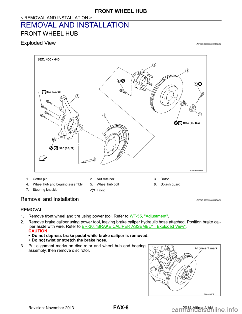
Exploded ViewINFOID:0000000009464438
Removal and InstallationINFOID:0000000009464439
REMOVAL
1. Remove front wheel and tire using power tool. Refer to WT-55, "Adjustment".
2. Remove brake caliper using power tool, leaving brak e caliper hydraulic hose attached. Position brake cal-
iper aside with wire. Refer to BR-36, "BRAKE CALIPER ASSEMBLY : Exploded View"
.
CAUTION:
• Do not depress brake pedal while brake caliper is removed.
• Do not twist or stretch the brake hose.
3. Put alignment marks on disc rotor and wheel hub and bearing assembly, then remove disc rotor.
1. Cotter pin 2. Nut retainer 3. Rotor
4. Wheel hub and bearing assembly 5. Wheel hub bolt 6. Splash guard
7. Steering knuckle Front
AWEIA0264ZZ
SDIA1480E
Revision: November 20132014 Altima NAM
Page 2462 of 4801

FAX-10
< REMOVAL AND INSTALLATION >
FRONT DRIVE SHAFT
FRONT DRIVE SHAFT
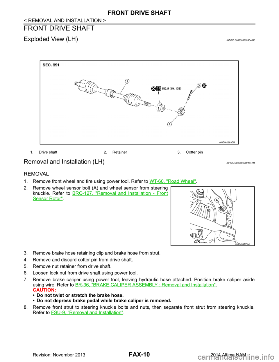
Exploded View (LH)INFOID:0000000009464440
Removal and Installation (LH)INFOID:0000000009464441
REMOVAL
1. Remove front wheel and tire using power tool. Refer to WT-60, "Road Wheel".
2. Remove wheel sensor bolt (A) and wheel sensor from steering knuckle. Refer to BRC-127, "Removal and Installation - Front
Sensor Rotor".
3. Remove brake hose retaining clip and brake hose from strut.
4. Remove and discard cotter pin from drive shaft.
5. Remove nut retainer from drive shaft.
6. Loosen lock nut from drive shaft using power tool.
7. Remove brake caliper using power tool, leaving hy draulic hose attached. Position brake caliper aside
using wire. Refer to BR-36, "BRAKE CALIPER ASSEMBLY : Removal and Installation"
.
CAUTION:
• Do not twist or stretch the brake hose.
• Do not depress brake pedal while brake caliper is removed.
8. Remove front strut to steering knuckle bolts and nut s, then separate front strut from steering knuckle.
Refer to FSU-9, "Removal and Installation"
.
1. Drive shaft 2. Retainer 3. Cotter pin
AWDIA0983GB
ALDIA0287ZZ
Revision: November 20132014 Altima NAM
Page 2465 of 4801

FRONT DRIVE SHAFTFAX-13
< REMOVAL AND INSTALLATION >
CEF
G H
I
J
K L
M A
B
FA X
N
O P
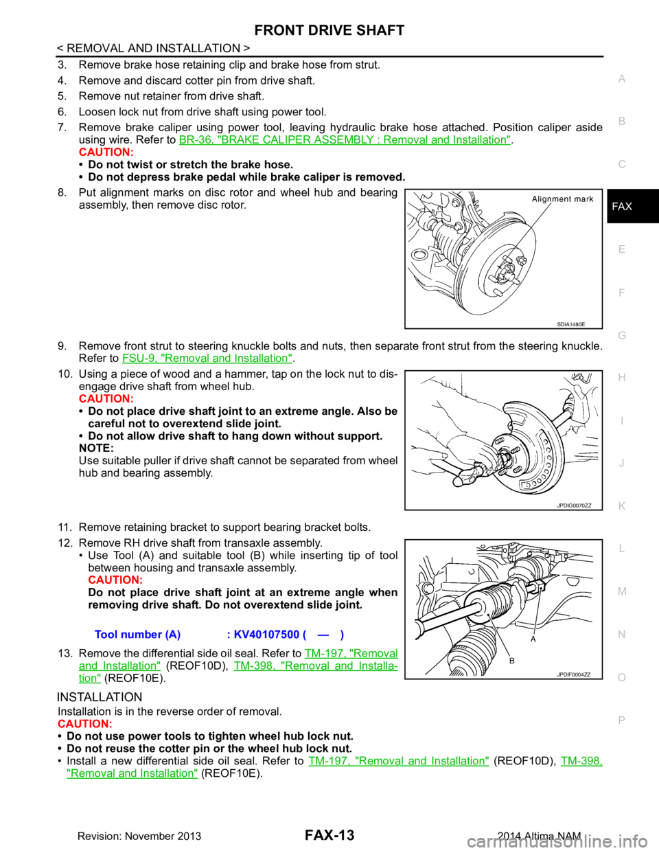
3. Remove brake hose retaining clip and brake hose from strut.
4. Remove and discard cotter pin from drive shaft.
5. Remove nut retainer from drive shaft.
6. Loosen lock nut from drive shaft using power tool.
7. Remove brake caliper using power tool, leaving hy draulic brake hose attached. Position caliper aside
using wire. Refer to BR-36, "BRAKE CALIPER ASSEMBLY : Removal and Installation"
.
CAUTION:
• Do not twist or stretch the brake hose.
• Do not depress brake pedal while brake caliper is removed.
8. Put alignment marks on disc rotor and wheel hub and bearing assembly, then remove disc rotor.
9. Remove front strut to steering knuckle bolts and nuts, then separate front strut from the steering knuckle.
Refer to FSU-9, "Removal and Installation"
.
10. Using a piece of wood and a hammer, tap on the lock nut to dis- engage drive shaft from wheel hub.
CAUTION:
• Do not place drive shaft joint to an extreme angle. Also be careful not to over extend slide joint.
• Do not allow drive shaft to hang down without support.
NOTE:
Use suitable puller if drive shaft cannot be separated from wheel
hub and bearing assembly.
11. Remove retaining bracket to support bearing bracket bolts.
12. Remove RH drive shaft from transaxle assembly. • Use Tool (A) and suitable tool (B) while inserting tip of tool
between housing and transaxle assembly.
CAUTION:
Do not place drive shaft join t at an extreme angle when
removing drive shaft. Do not overextend slide joint.
13. Remove the differential side oil seal. Refer to TM-197, "Removal
and Installation" (REOF10D), TM-398, "Removal and Installa-
tion" (REOF10E).
INSTALLATION
Installation is in the reverse order of removal.
CAUTION:
• Do not use power tools to tighten wheel hub lock nut.
• Do not reuse the cotter pin or the wheel hub lock nut.
• Install a new differential side oil seal. Refer to TM-197, "Removal and Installation"
(REOF10D), TM-398,
"Removal and Installation" (REOF10E).
SDIA1480E
JPDIG0070ZZ
Tool number (A) : KV40107500 ( — )
JPDIF0004ZZ
Revision: November 20132014 Altima NAM
Page 2492 of 4801

FL-12
< REMOVAL AND INSTALLATION >
FUEL TANK
8. Remove rear wheel and tire using power tool. Refer to WT-55, "Adjustment".
9. Remove rear brake pads. Refer to BR-38, "BRAKE PAD : Removal and Installation"
.
10. Remove rear torque members and rear disc brake rotor.
11. Disconnect rear parking brake shoe, and remove rear cables from toggle lever. Refer to PB-9, "Removal
and Installation".
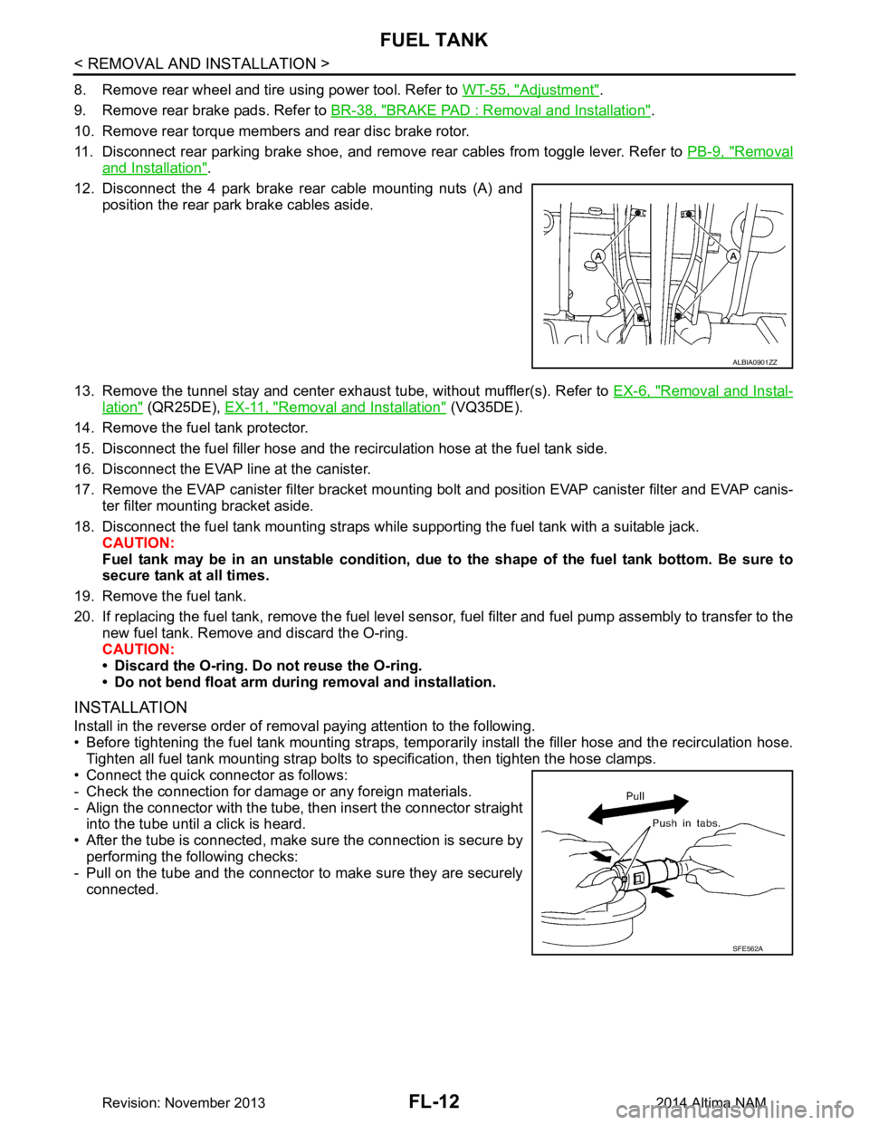
12. Disconnect the 4 park brake rear cable mounting nuts (A) and position the rear park brake cables aside.
13. Remove the tunnel stay and center exhaust tube, without muffler(s). Refer to EX-6, "Removal and Instal-
lation" (QR25DE), EX-11, "Removal and Installation" (VQ35DE).
14. Remove the fuel tank protector.
15. Disconnect the fuel filler hose and the recirculation hose at the fuel tank side.
16. Disconnect the EVAP line at the canister.
17. Remove the EVAP canister filter bracket mounti ng bolt and position EVAP canister filter and EVAP canis-
ter filter mounting bracket aside.
18. Disconnect the fuel tank mounting straps while supporting the fuel tank with a suitable jack. CAUTION:
Fuel tank may be in an unstable condition, due to the shape of the fuel tank bottom. Be sure to
secure tank at all times.
19. Remove the fuel tank.
20. If replacing the fuel tank, remove the fuel level sens or, fuel filter and fuel pump assembly to transfer to the
new fuel tank. Remove and discard the O-ring.
CAUTION:
• Discard the O-ring. Do not reuse the O-ring.
• Do not bend float arm during removal and installation.
INSTALLATION
Install in the reverse order of removal paying attention to the following.
• Before tightening the fuel tank mounting straps, tempor arily install the filler hose and the recirculation hose.
Tighten all fuel tank mounting strap bolts to specification, then tighten the hose clamps.
• Connect the quick connector as follows:
- Check the connection for damage or any foreign materials.
- Align the connector with the tube, then insert the connector straight into the tube until a click is heard.
• After the tube is connected, make sure the connection is secure by performing the following checks:
- Pull on the tube and the connector to make sure they are securely
connected.
ALBIA0901ZZ
SFE562A
Revision: November 20132014 Altima NAM