2011 Hyundai Accent Owner's Manual - RHD (UK. Australia)
-
 1
1 -
 2
2 -
 3
3 -
 4
4 -
 5
5 -
 6
6 -
 7
7 -
 8
8 -
 9
9 -
 10
10 -
 11
11 -
 12
12 -
 13
13 -
 14
14 -
 15
15 -
 16
16 -
 17
17 -
 18
18 -
 19
19 -
 20
20 -
 21
21 -
 22
22 -
 23
23 -
 24
24 -
 25
25 -
 26
26 -
 27
27 -
 28
28 -
 29
29 -
 30
30 -
 31
31 -
 32
32 -
 33
33 -
 34
34 -
 35
35 -
 36
36 -
 37
37 -
 38
38 -
 39
39 -
 40
40 -
 41
41 -
 42
42 -
 43
43 -
 44
44 -
 45
45 -
 46
46 -
 47
47 -
 48
48 -
 49
49 -
 50
50 -
 51
51 -
 52
52 -
 53
53 -
 54
54 -
 55
55 -
 56
56 -
 57
57 -
 58
58 -
 59
59 -
 60
60 -
 61
61 -
 62
62 -
 63
63 -
 64
64 -
 65
65 -
 66
66 -
 67
67 -
 68
68 -
 69
69 -
 70
70 -
 71
71 -
 72
72 -
 73
73 -
 74
74 -
 75
75 -
 76
76 -
 77
77 -
 78
78 -
 79
79 -
 80
80 -
 81
81 -
 82
82 -
 83
83 -
 84
84 -
 85
85 -
 86
86 -
 87
87 -
 88
88 -
 89
89 -
 90
90 -
 91
91 -
 92
92 -
 93
93 -
 94
94 -
 95
95 -
 96
96 -
 97
97 -
 98
98 -
 99
99 -
 100
100 -
 101
101 -
 102
102 -
 103
103 -
 104
104 -
 105
105 -
 106
106 -
 107
107 -
 108
108 -
 109
109 -
 110
110 -
 111
111 -
 112
112 -
 113
113 -
 114
114 -
 115
115 -
 116
116 -
 117
117 -
 118
118 -
 119
119 -
 120
120 -
 121
121 -
 122
122 -
 123
123 -
 124
124 -
 125
125 -
 126
126 -
 127
127 -
 128
128 -
 129
129 -
 130
130 -
 131
131 -
 132
132 -
 133
133 -
 134
134 -
 135
135 -
 136
136 -
 137
137 -
 138
138 -
 139
139 -
 140
140 -
 141
141 -
 142
142 -
 143
143 -
 144
144 -
 145
145 -
 146
146 -
 147
147 -
 148
148 -
 149
149 -
 150
150 -
 151
151 -
 152
152 -
 153
153 -
 154
154 -
 155
155 -
 156
156 -
 157
157 -
 158
158 -
 159
159 -
 160
160 -
 161
161 -
 162
162 -
 163
163 -
 164
164 -
 165
165 -
 166
166 -
 167
167 -
 168
168 -
 169
169 -
 170
170 -
 171
171 -
 172
172 -
 173
173 -
 174
174 -
 175
175 -
 176
176 -
 177
177 -
 178
178 -
 179
179 -
 180
180 -
 181
181 -
 182
182 -
 183
183 -
 184
184 -
 185
185 -
 186
186 -
 187
187 -
 188
188 -
 189
189 -
 190
190 -
 191
191 -
 192
192 -
 193
193 -
 194
194 -
 195
195 -
 196
196 -
 197
197 -
 198
198 -
 199
199 -
 200
200 -
 201
201 -
 202
202 -
 203
203 -
 204
204 -
 205
205 -
 206
206 -
 207
207 -
 208
208 -
 209
209 -
 210
210 -
 211
211 -
 212
212 -
 213
213 -
 214
214 -
 215
215 -
 216
216 -
 217
217 -
 218
218 -
 219
219 -
 220
220 -
 221
221 -
 222
222 -
 223
223 -
 224
224 -
 225
225 -
 226
226 -
 227
227 -
 228
228 -
 229
229 -
 230
230 -
 231
231
 6 DO-IT-YOURSELF MAINTENANCE
28
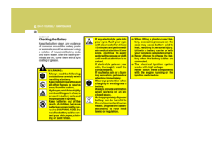
G275H01MC-GAT Interior Light
1. Remove the cover with a flat-head
screwdriver.
2. Replace with a new bulb.
OMC055030
G270G01MC-GAT Map Light (If Installed)
1. Remove")
 6
DO-IT-YOURSELF MAINTENANCE
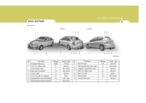
29BULB WATTAGE
G280A01MC-DAT
OMC059020N
Socket Type P43t-38
BAU15s
W2.1X9.5d W2.1X9.5d
S8.5/8.5PG13
LED Type
W2.1X9.5d Part Name
Stop/Tail Light
High Mounted Rear Stop Lig")
 6 DO-IT-YOURSELF MAINTENANCE
30FUSE PANEL DESCRIPTION
G200C01MC-DAT Engine Compartment NOTE: Not all fuse panel descriptions in this manual may be applicable to your vehicle. It is accurate at the tim")
 6
DO-IT-YOURSELF MAINTENANCE
31
G200E01MC-GAT Inner Panel
G200E01MCFUSE RATING
25A 25A 10A 25A10A 10A15A 25A 10A 10A 20A10A 10A 30A 25A 10A 10A15A 10A 10A CIRCUIT PROTECTED
Driver Power Window Switch,")
 6 DO-IT-YOURSELF MAINTENANCE
32
FUSE RATING10A 20A10A 10A 15A 10A10A 20A 10A 15A 10A 15A 10A10A 10A 10A 10A CIRCUIT PROTECTED
Front Fog Lamp Switch, Front Fog Lamp LH, Front Fog Lamp RH,BCM Sunroof Mo")
 Emission Control System ............................................. 7-2
Catalytic Converter ...................................................... 7-3
7
EMISSION CONTROL SYSTEM
7")
 7EMISSION CONTROL SYSTEMS
2EMISSION CONTROL SYS- TEM
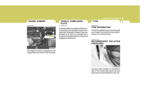
H010A01A-DAT Your Hyundai is equipped with an
emission control system to meet all Australian Design Rules(ADR) require- ments.
There are three emis")
 7
EMISSION CONTROL SYSTEMS
3CATALYTIC CONVERTER
H020A01A-DAT
(If Installed)
The catalytic converter is part of the
exhaust emission control system. Its purpose is to remove certain engineemission prod")