2010 JAGUAR XFR wiring
[x] Cancel search: wiringPage 1900 of 3039
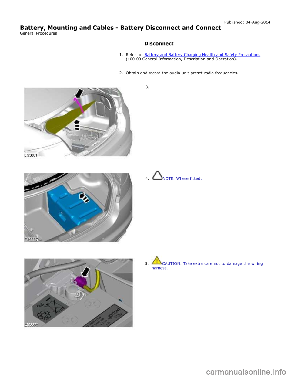
(100-00 General Information, Description and Operation).
2. Obtain and record the audio unit preset radio frequencies.
3.
4. NOTE: Where fitted.
5. CAUTION: Take extra care not to damage the wiring
harness.
Page 1934 of 3039
Published: 11-May-2011
Information and Entertainment System - General Information - Cellular
Phone
Diagnosis and Testing
Principle of Operation
For a detailed description of the Cellular Phone System, refer to the relevant Description and Operation sections in the
workshop manual.
Inspection and Verification
CAUTION: Diagnosis by substitution from a donor vehicle is NOT acceptable. Substitution of control modules does not
guarantee confirmation of a fault, and may also cause additional faults in the vehicle being tested and/or the donor vehicle.
1. Verify the customer concern.
2. Visually inspect for obvious signs of damage and system integrity.
Visual Inspection
Mechanical Electrical
Microphone
Bluetooth antenna
Electrical connectors
Wiring harness for damage or corrosion
Fuses
3. If an obvious cause for an observed or reported concern is found, correct the cause (if possible) before proceeding to
the next step.
4. If the cause is not visually evident, verify the symptom and refer to the Symptom Chart, alternatively check for
Diagnostic Trouble Codes (DTCs) and refer to the relevant DTC Index.
Symptom Chart
Symptom Action Unable to pair
GO to Pinpoint Test A. Not Auto Connecting
GO to Pinpoint Test B. No Audio to 3rd Party
GO to Pinpoint Test C. No Audio from 3rd Party
GO to Pinpoint Test D. No Audio
GO to Pinpoint Test E. DTC Index
CAUTION: When probing connectors to take measurements in the course of the pinpoint tests, use the adaptor kit, part
number 3548-1358-00
NOTES:
If the control module or a component is suspect and the vehicle remains under manufacturer warranty, refer to the
Warranty Policy and Procedures manual (section B1.2), or determine if any prior approval programme is in operation, prior to
the installation of a new module/component.
Generic scan tools may not read the codes listed, or may read only five digit codes. Match the five digits from the scan
tool to the first five digits of the seven digit code listed to identify the fault (the last two digits give extra information read by
the manufacturer-approved diagnostic system).
When performing voltage or resistance tests, always use a digital multimeter (DMM) accurate to three decimal places and
with a current calibration certificate. When testing resistance, always take the resistance of the DMM leads into account.
Page 1956 of 3039
controlled through the device itself.
NOTE: The system will support devices with a storage capacity up to 256 GB which is approximately 65,000 audio tracks.
The wiring link harness between the portable audio module and interface panel consists of hardwired and digital connections
for data and signal exchange. The MOST carries the communication signals and information between the portable audio module
to the IAM and touch-screen. Audio output to the speaker system is controlled by the IAM or power amplifier depending on the
audio system specification.
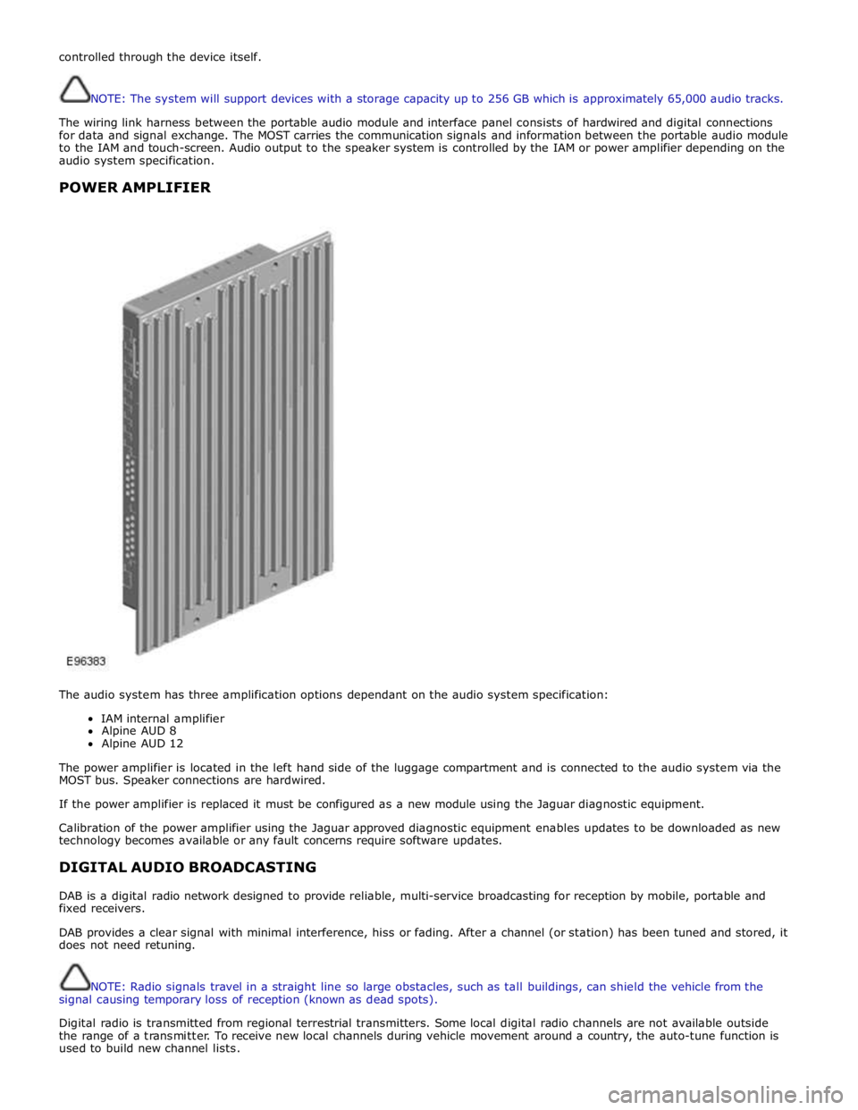
POWER AMPLIFIER
The audio system has three amplification options dependant on the audio system specification:
IAM internal amplifier
Alpine AUD 8
Alpine AUD 12
The power amplifier is located in the left hand side of the luggage compartment and is connected to the audio system via the
MOST bus. Speaker connections are hardwired.
If the power amplifier is replaced it must be configured as a new module using the Jaguar diagnostic equipment.
Calibration of the power amplifier using the Jaguar approved diagnostic equipment enables updates to be downloaded as new
technology becomes available or any fault concerns require software updates.
DIGITAL AUDIO BROADCASTING
DAB is a digital radio network designed to provide reliable, multi-service broadcasting for reception by mobile, portable and
fixed receivers.
DAB provides a clear signal with minimal interference, hiss or fading. After a channel (or station) has been tuned and stored, it
does not need retuning.
NOTE: Radio signals travel in a straight line so large obstacles, such as tall buildings, can shield the vehicle from the
signal causing temporary loss of reception (known as dead spots).
Digital radio is transmitted from regional terrestrial transmitters. Some local digital radio channels are not available outside
the range of a transmitter. To receive new local channels during vehicle movement around a country, the auto-tune function is
used to build new channel lists.
Page 2036 of 3039
Rear Fog Lamp
The rear fog lamps are located in separate units attached to the luggage compartment lid. The rear fog lamps each use 3 high
intensity LED's. The fog lamp locates in a recess in the luggage compartment lid has a seal to prevent the ingress of water into the luggage compartment. The lamp is secured in the recess with a metal securing clip. The rear fog lamp is activated
using a button located on the auxiliary lighting switch in the instrument panel.
LICENCE PLATE LAMPS
Two licence plate lamps are located in the luggage compartment lid trim finisher. One is located adjacent to the emergency
luggage compartment lid release key barrel cover and the other is adjacent to the rear view camera (if fitted). The licence plate
lamps are active at all times when the side lamps are operating. Each lamp can be removed from the finisher by inserting a
wide, flat screwdriver blade or similar tool in a slot between the lamp lens and the finisher and gently levering the lamp from
the surround. The bulb is a push fit in a holder which in turn is a press fit in the lamp housing.
HIGH MOUNTED STOP LAMP
The high mounted stop lamp is located at the bottom of the rear windshield. The lamp is secured to a bezel in the parcel shelf
with 2 screws.
The high mounted stop lamp uses 12, red colored LED's which illuminate through a clear lens. The high mounted stop lamp functionality is the same as that described for the stop lamps.
TURN SIGNAL INDICATOR SIDE REPEATER LAMPS
The turn signal indicator side repeaters are located in each door mirror. On vehicles from 10MY the lamp is an LED unit which illuminates in an orange color. The LED unit is secured to the mirror bezel with 2 screws and is connected to the mirror wiring harness with a 2 pin connector.
The side repeaters have the same functionality and operate in conjunction with the front and rear turn signal indicators and
the hazard warning flashers.
HAZARD FLASHERS
The hazard flashers are activated by a non-latching switch located in the switch pack located in the center of the instrument
panel. The hazard flashers operate at all times when selected and operate independent of the ignition mode.
When the hazard flashers are selected on by the driver, a ground path is momentarily completed to the CJB which activates the front and rear and side repeater turn signal indicators. A second press of the switch is sensed by the CJB and the hazard flasher are deactivated. When the hazard flashers are active, they override any request for turn signal indicator operation.
The hazard flashers can also be activated by a crash signal from the RCM. Refer to: Air Bag and Safety Belt Pretensioner Supplemental Restraint System (SRS) (501-20B Supplemental Restraint System, Description and Operation).
Page 2037 of 3039
Exterior Lighting - Headlamps
Diagnosis and Testing
Principles of Operation Published: 11-Jul-2014
For a detailed description of the exterior lighting system, refer to the relevant Description and Operation section in the
workshop manual. REFER to: (417-01 Exterior Lighting)
Exterior Lighting (Description and Operation), Exterior Lighting (Description and Operation), Exterior Lighting (Description and Operation).
Safety Information
WARNINGS:
The Xenon Headlamp system generates up to 28,000 volts. Make sure that the headlamps are switched off before
working on the system. Failure to follow this instruction may lead to fatality.
The following safety precautions must be followed when working on the Xenon Headlamp system:
DO NOT attempt any procedures on the Xenon Headlamps or circuits when the system is energized.
Handling of the xenon bulb must be performed using suitable protective equipment, e.g. gloves and goggles. The glass
part of the bulb must not be touched.
Only operate the lamp in a mounted condition in the reflector.
All safety procedures and precautions must be followed to prevent personal injury.
CAUTION: Xenon bulbs must be disposed of as hazardous waste.
There are instructions on the correct procedures for Xenon Headlamp System repairs in the manual, refer to section 100-00 -
General Information, Standard Workshop Practices of the workshop manual.
Inspection and Verification
CAUTION: Diagnosis by substitution from a donor vehicle is NOT acceptable. Substitution of control modules does not
guarantee confirmation of a fault, and may also cause additional faults in the vehicle being tested and/or the donor vehicle.
1. Verify the customer concern.
2. Visually inspect for obvious signs of damage.
3. If an obvious cause for an observed or reported concern is found, correct the cause (if possible) before proceeding to
the next step.
4. If the cause is not visually evident, check for Diagnostic Trouble Codes (DTCs) and refer to DTC Index.
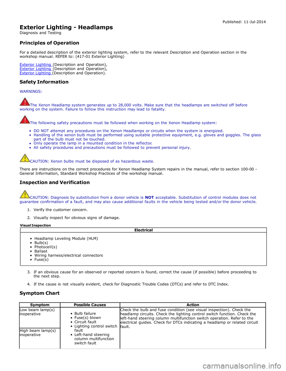
Symptom Chart
Symptom Possible Causes Action Low beam lamp(s)
inoperative
Bulb failure
Fuse(s) blown
Circuit fault
Lighting control switch
fault
Left-hand steering
column multifunction
switch fault Check the bulb and fuse condition (see visual inspection). Check the
headlamp circuits. Check the lighting control switch function. Check the
left-hand steering column multifunction switch operation. Refer to the
electrical guides. Check for DTCs indicating a headlamp or related circuit
fault. High beam lamp(s)
inoperative Electrical
Headlamp Leveling Module (HLM)
Bulb(s)
Photocell(s)
Ballast
Wiring harness/electrical connectors
Fuse(s) Visual Inspection
Page 2061 of 3039
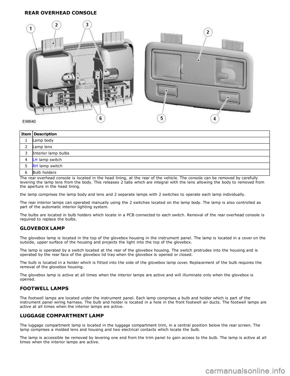
1 Lamp body 2 Lamp lens 3 Interior lamp bulbs 4 LH lamp switch 5 RH lamp switch 6 Bulb holders The rear overhead console is located in the head lining, at the rear of the vehicle. The console can be removed by carefully
levering the lamp lens from the body. This releases 2 tabs which are integral with the lens allowing the body to removed from
the aperture in the head lining.
the lamp comprises the lamp body and lens and 2 separate lamps with 2 switches to operate each lamp individually.
The rear interior lamps can operated manually using the 2 switches located on the lamp body. The lamp is also controlled as
part of the automatic interior lighting system.
The bulbs are located in bulb holders which locate in a PCB connected to each switch. Removal of the rear overhead console is
required to replace the bulbs.
GLOVEBOX LAMP
The glovebox lamp is located in the top of the glovebox housing in the instrument panel. The lamp is located in a cover on the
outside, upper surface of the housing and projects the light into the top of the glovebox.
The lamp is operated by a switch located at the rear of the glovebox housing. The switch protrudes into the housing and is
operated by the rear face of the glovebox lid tray when the glovebox is opened or closed.
The bulb is located in a holder which is fitted into the side of the glovebox lamp cover. Replacement of the bulb requires the
removal of the glovebox housing.
The glovebox lamp is active at all times when the interior lamps are active and will illuminate only when the glovebox is
opened.
FOOTWELL LAMPS
The footwell lamps are located under the instrument panel. Each lamp comprises a bulb and holder which is part of the
instrument panel wiring harness. The bulb and holder is located in a hole in the front footwell air ducts. The footwell lamps are
active at all times when the interior lamps are active.
LUGGAGE COMPARTMENT LAMP
The luggage compartment lamp is located in the luggage compartment trim, in a central position below the rear screen. The
lamp comprises a molded lens and housing and two electrical contacts which locate the bulb.
The lamp is accessible be removed by levering one end from the trim panel to gain access to the bulb. The lamp is active at all
times when the interior lamps are active.
Page 2063 of 3039
Interior Lighting - Interior Lighting
Diagnosis and Testing
Principles of Operation Published: 11-May-2011
For a detailed description of the interior lighting system, refer to the relevant Description and Operation sections in the
workshop manual. REFER to: (417-02 Interior Lighting)
Interior Lighting (Description and Operation), Interior Lighting (Description and Operation), Interior Lighting (Description and Operation).
Inspection and Verification
CAUTION: Diagnosis by substitution from a donor vehicle is NOT acceptable. Substitution of control modules does not
guarantee confirmation of a fault, and may also cause additional faults in the vehicle being tested and/or the donor vehicle.
1. Verify the customer concern.
2. Visually inspect for obvious signs of damage and system integrity.
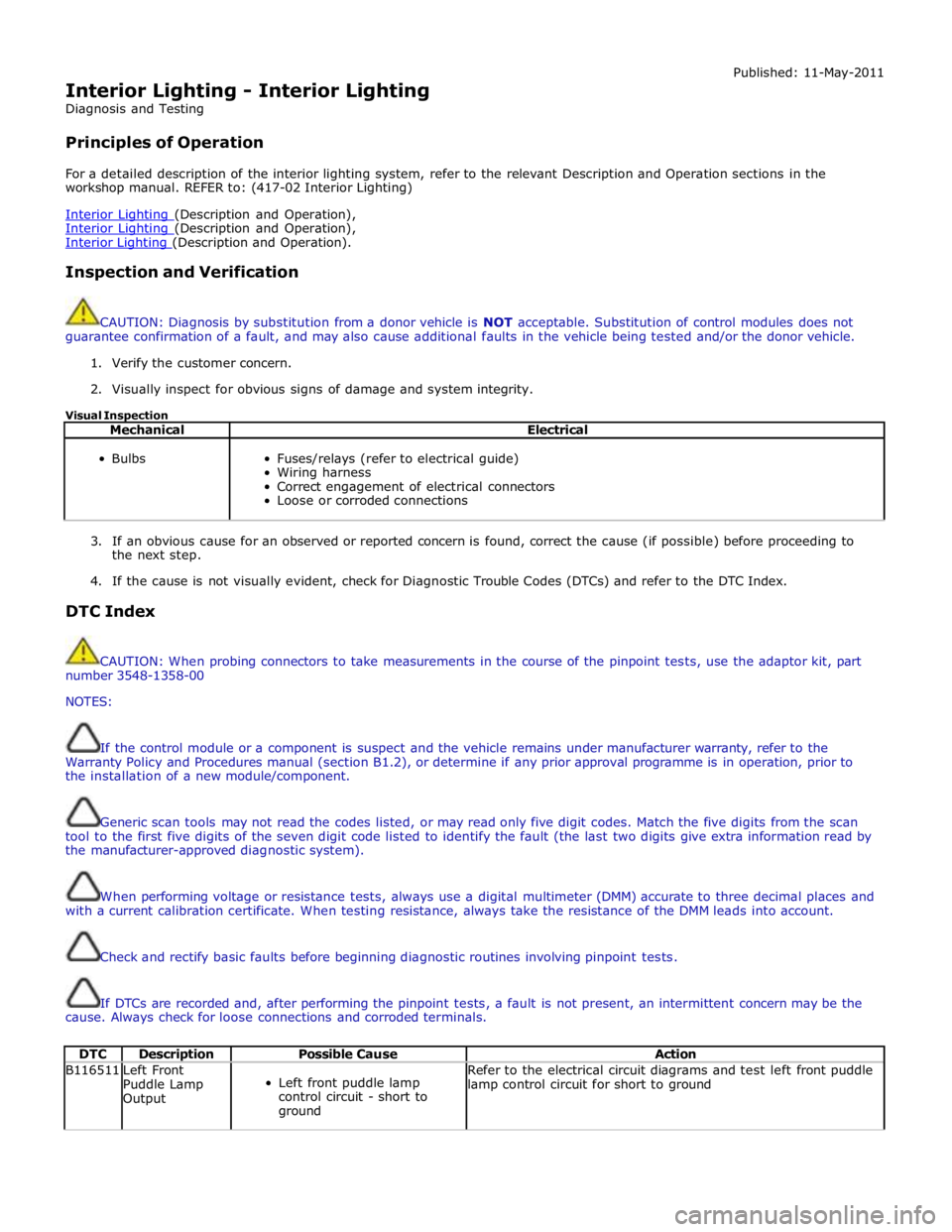
Visual Inspection
Mechanical Electrical
Bulbs
Fuses/relays (refer to electrical guide)
Wiring harness
Correct engagement of electrical connectors
Loose or corroded connections
3. If an obvious cause for an observed or reported concern is found, correct the cause (if possible) before proceeding to
the next step.
4. If the cause is not visually evident, check for Diagnostic Trouble Codes (DTCs) and refer to the DTC Index.
DTC Index
CAUTION: When probing connectors to take measurements in the course of the pinpoint tests, use the adaptor kit, part
number 3548-1358-00
NOTES:
If the control module or a component is suspect and the vehicle remains under manufacturer warranty, refer to the
Warranty Policy and Procedures manual (section B1.2), or determine if any prior approval programme is in operation, prior to
the installation of a new module/component.
Generic scan tools may not read the codes listed, or may read only five digit codes. Match the five digits from the scan
tool to the first five digits of the seven digit code listed to identify the fault (the last two digits give extra information read by
the manufacturer-approved diagnostic system).
When performing voltage or resistance tests, always use a digital multimeter (DMM) accurate to three decimal places and
with a current calibration certificate. When testing resistance, always take the resistance of the DMM leads into account.
Check and rectify basic faults before beginning diagnostic routines involving pinpoint tests.
If DTCs are recorded and, after performing the pinpoint tests, a fault is not present, an intermittent concern may be the
cause. Always check for loose connections and corroded terminals.
DTC Description Possible Cause Action B116511
Left Front
Puddle Lamp
Output
Left front puddle lamp
control circuit - short to
ground Refer to the electrical circuit diagrams and test left front puddle
lamp control circuit for short to ground
Page 2067 of 3039
Published: 11-May-2011
Module Communications Network - Communications Network - Overview
Description and Operation
OVERVIEW
A number of different types of communication network are incorporated into the vehicle wiring harnesses for the transmission
of commands and information between control modules. The configuration installed on a particular vehicle depends on the
model and equipment level.
NOTE: The control diagrams shown later in this section are schematics reflecting communications networks fitted to LH
(left-hand) vehicles only. For detailed layouts of the various communications networks fitted to LHD (left-hand drive) and RHD
(right-hand drive) vehicles, refer to the Electrical Guide.
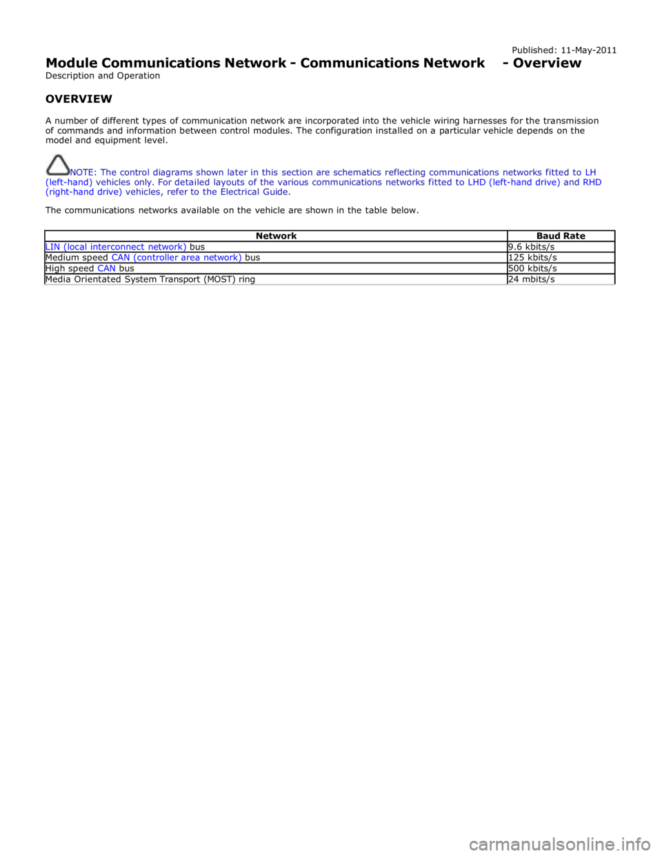
The communications networks available on the vehicle are shown in the table below.
Network Baud Rate LIN (local interconnect network) bus 9.6 kbits/s Medium speed CAN (controller area network) bus 125 kbits/s High speed CAN bus 500 kbits/s Media Orientated System Transport (MOST) ring 24 mbits/s