2010 JAGUAR XFR wiring
[x] Cancel search: wiringPage 2153 of 3039
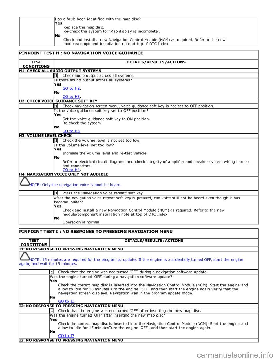
PINPOINT TEST H : NO NAVIGATION VOICE GUIDANCE TEST
CONDITIONS DETAILS/RESULTS/ACTIONS H1: CHECK ALL AUDIO OUTPUT SYSTEMS 1 Check audio output across all systems. Is there sound output across all systems? Yes
GO to H2. No
GO to H3. H2: CHECK VOICE GUIDANCE SOFT KEY 1 Check navigation screen menu, voice guidance soft key is not set to OFF position. Is the voice guidance soft key set to OFF position? Yes
Set the voice guidance soft key to ON position.
Re-check the system
No
GO to H3. H3: VOLUME LEVEL CHECK 1 Check the volume level is not set too low. Is the volume level set too low? Yes
Increase the volume level and re-test vehicle.
No
Refer to electrical circuit diagrams and check integrity of amplifier and speaker system wiring harness
and connectors.
GO to H4. H4: NAVIGATION VOICE ONLY NOT AUDIBLE
NOTE: Only the navigation voice cannot be heard. 1 Press the 'Navigation voice repeat' soft key. After the navigation voice repeat soft key is pressed, can voice still not be heard even though it has
become louder? Yes
Check and install a new Navigation Control Module (NCM) as required. Refer to the new
module/component installation note at top of DTC Index.
No
Operation is normal.
PINPOINT TEST I : NO RESPONSE TO PRESSING NAVIGATION MENU TEST
CONDITIONS DETAILS/RESULTS/ACTIONS I1: NO RESPONSE TO PRESSING NAVIGATION MENU
NOTE: 15 minutes are required for the program to update. If the engine is accidentally turned OFF, start the engine
again, and wait for 15 minutes. 1 Check that the engine was not turned 'OFF' during a navigation software update. Was the engine turned 'OFF' during a navigation software update? Yes
Check the correct map disc is inserted into the Navigation Control Module (NCM). Start the engine and
allow to idle for 15 minutesTurn the engine 'OFF', and then start the engine again.Verify that the
navigation screen displays. Navigation was in the program update mode.
No
GO to I3. I2: NO RESPONSE TO PRESSING NAVIGATION MENU 1 Check that the engine was not turned 'OFF' after inserting the new map disc. Was the engine turned 'OFF' after inserting the new map disc? Yes
Check the correct map disc is inserted into the Navigation Control Module (NCM). Start the engine and
allow to idle for 15 minutesTurn the engine 'OFF', and then start the engine again.
No
GO to I3. I3: NO RESPONSE TO PRESSING NAVIGATION MENU Has a fault been identified with the map disc?
Yes
Replace the map disc.
Re-check the system for 'Map display is incomplete'.
No
Check and install a new Navigation Control Module (NCM) as required. Refer to the new
module/component installation note at top of DTC Index.
Page 2154 of 3039

Check the "Loading" button on the navigation diagnostics screen (PIN code 660) has been pressed, and "YES" has been selected. Has the "Loading" button on the navigation diagnostics screen been pressed, and has "YES" been selected? Yes
Check the correct map disc is inserted into the Navigation Control Module (NCM). Start the engine and
allow to idle for 15 minutesTurn the engine 'OFF', and then start the engine again.
No
Refer to electrical circuit diagrams and check integrity of navigation system wiring harness and
connectors.
GO to I4. I4: SYSTEM CHECK FOR DTCS 1 Check the system for DTCs which may be logged. Is DTC U300055 logged? Yes
Using the manufacturer approved diagnostic system check/amend the Car Configuration File parameter in
block 2, byte 127 to match vehicle market/specification. If the DTC remains check navigation system
module part number and ensure the correct component is installed to vehicle market/specification.
No
GO to I5. I5: NO RESPONSE TO PRESSING NAVIGATION MENU 1 Turn the engine 'OFF', wait for a moment, and then turn the engine 'ON' again. Does the navigation screen fail to display even if the navigation button is pressed? Yes
Check the HLDF is installed correctly.
Check the Navigation Control Module (NCM) is installed correctly.
No
Operation is normal. DTC Index
For a list of Diagnostic Trouble Codes (DTCs) that could be logged on this vehicle, please refer to Section 100-00.
REFER to: Diagnostic Trouble Code (DTC) Index - DTC: Navigation Control Module (NCM) (100-00, Description and Operation).
Page 2173 of 3039
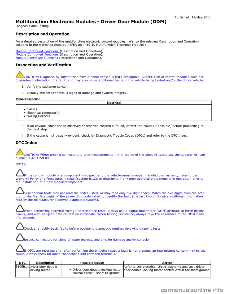
Multifunction Electronic Modules - Driver Door Module (DDM)
Diagnosis and Testing
Description and Operation Published: 11-May-2011
For a detailed description of the multifunction electronic control modules, refer to the relevant Description and Operation
sections in the workshop manual. REFER to: (419-10 Multifunction Electronic Modules)
Module Controlled Functions (Description and Operation), Module Controlled Functions (Description and Operation), Module Controlled Functions (Description and Operation).
Inspection and Verification
CAUTION: Diagnosis by substitution from a donor vehicle is NOT acceptable. Substitution of control modules does not
guarantee confirmation of a fault, and may also cause additional faults in the vehicle being tested and/or the donor vehicle.
1. Verify the customer concern.
2. Visually inspect for obvious signs of damage and system integrity.
3. If an obvious cause for an observed or reported concern is found, correct the cause (if possible) before proceeding to
the next step.
4. If the cause is not visually evident, check for Diagnostic Trouble Codes (DTCs) and refer to the DTC Index.
DTC Index
CAUTION: When probing connectors to take measurements in the course of the pinpoint tests, use the adaptor kit, part
number 3548-1358-00.
NOTES:
If the control module or a component is suspect and the vehicle remains under manufacturer warranty, refer to the
Warranty Policy and Procedures manual (section B1.2), or determine if any prior approval programme is in operation, prior to
the installation of a new module/component.
Generic scan tools may not read the codes listed, or may read only five digit codes. Match the five digits from the scan
tool to the first five digits of the seven digit code listed to identify the fault (the last two digits give additional information
read by the manufacturer approved diagnostic system).
When performing electrical voltage or resistance tests, always use a digital multimeter (DMM) accurate to three decimal
places, and with an up-to-date calibration certificate. When testing resistance, always take the resistance of the DMM leads
into account.
Check and rectify basic faults before beginning diagnostic routines involving pinpoint tests.
Inspect connectors for signs of water ingress, and pins for damage and/or corrosion.
If DTCs are recorded and, after performing the pinpoint tests, a fault is not present, an intermittent concern may be the
cause. Always check for loose connections and corroded terminals.
DTC Description Possible Cause Action B10EB11
Driver door double
locking motor
Driver door double locking motor
control circuit - short to ground Refer to the electrical circuit diagrams and test driver
door double locking motor control circuit for short ground Electrical
Fuse(s)
Electrical connector(s)
Wiring Harness Visual Inspection
Page 2178 of 3039
Published: 11-May-2011
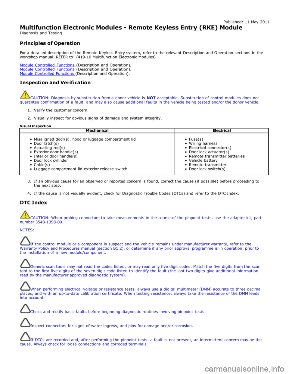
Multifunction Electronic Modules - Remote Keyless Entry (RKE) Module
Diagnosis and Testing
Principles of Operation
For a detailed description of the Remote Keyless Entry system, refer to the relevant Description and Operation sections in the
workshop manual. REFER to: (419-10 Multifunction Electronic Modules)
Module Controlled Functions (Description and Operation), Module Controlled Functions (Description and Operation), Module Controlled Functions (Description and Operation).
Inspection and Verification
CAUTION: Diagnosis by substitution from a donor vehicle is NOT acceptable. Substitution of control modules does not
guarantee confirmation of a fault, and may also cause additional faults in the vehicle being tested and/or the donor vehicle.
1. Verify the customer concern.
2. Visually inspect for obvious signs of damage and system integrity.
Visual Inspection
Mechanical Electrical
Misaligned door(s), hood or luggage compartment lid
Door latch(s)
Actuating rod(s)
Exterior door handle(s)
Interior door handle(s)
Door lock cylinder
Cable(s)
Luggage compartment lid exterior release switch
Fuse(s)
Wiring harness
Electrical connector(s)
Door lock actuator(s)
Remote transmitter batteries
Vehicle battery
Remote transmitter
Door lock switch(s)
3. If an obvious cause for an observed or reported concern is found, correct the cause (if possible) before proceeding to
the next step.
4. If the cause is not visually evident, check for Diagnostic Trouble Codes (DTCs) and refer to the DTC Index.
DTC Index
CAUTION: When probing connectors to take measurements in the course of the pinpoint tests, use the adaptor kit, part
number 3548-1358-00.
NOTES:
If the control module or a component is suspect and the vehicle remains under manufacturer warranty, refer to the
Warranty Policy and Procedures manual (section B1.2), or determine if any prior approval programme is in operation, prior to
the installation of a new module/component.
Generic scan tools may not read the codes listed, or may read only five digit codes. Match the five digits from the scan
tool to the first five digits of the seven digit code listed to identify the fault (the last two digits give additional information
read by the manufacturer approved diagnostic system).
When performing electrical voltage or resistance tests, always use a digital multimeter (DMM) accurate to three decimal
places, and with an up-to-date calibration certificate. When testing resistance, always take the resistance of the DMM leads
into account.
Check and rectify basic faults before beginning diagnostic routines involving pinpoint tests.
Inspect connectors for signs of water ingress, and pins for damage and/or corrosion.
If DTCs are recorded and, after performing the pinpoint tests, a fault is not present, an intermittent concern may be the
cause. Always check for loose connections and corroded terminals.
Page 2182 of 3039
Published: 11-May-2011
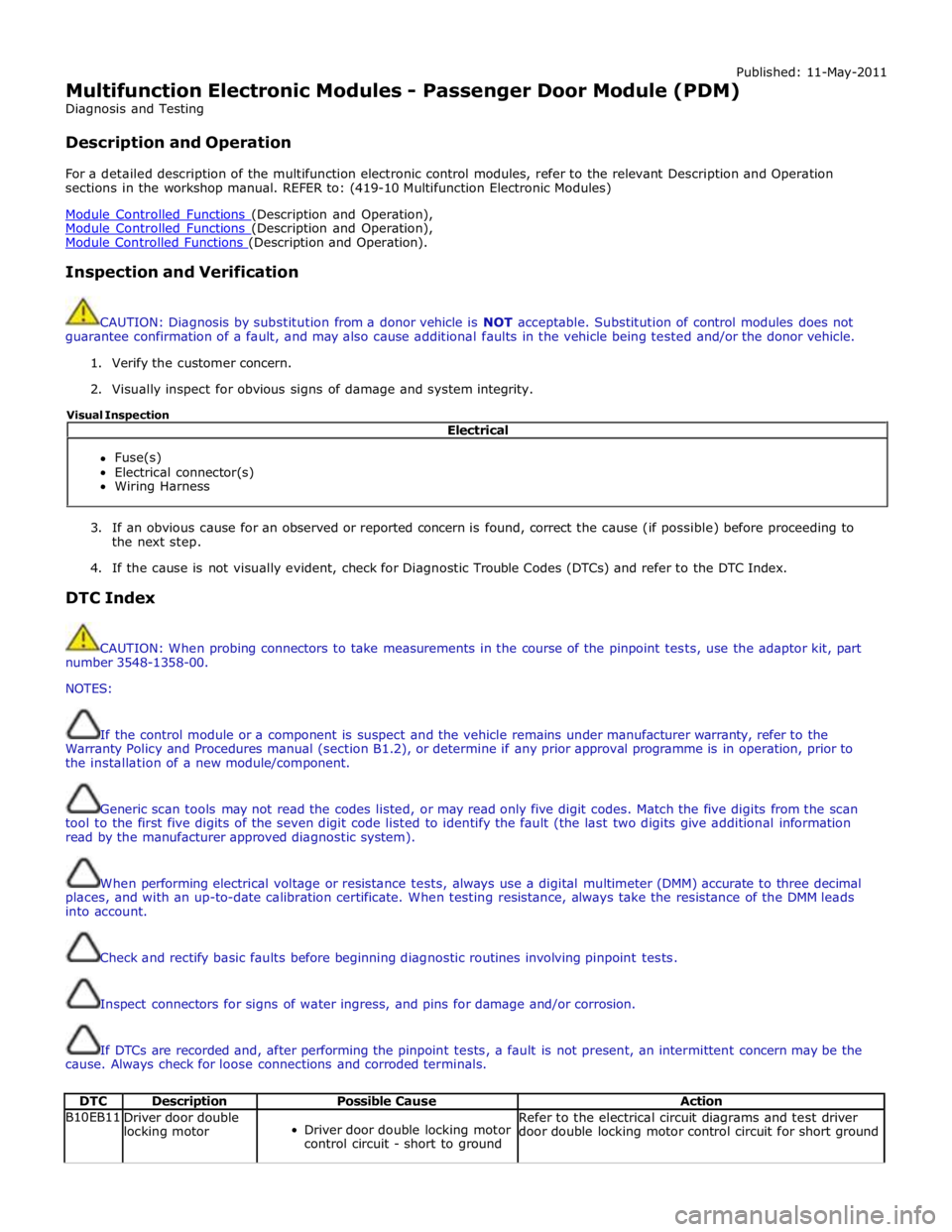
Multifunction Electronic Modules - Passenger Door Module (PDM)
Diagnosis and Testing
Description and Operation
For a detailed description of the multifunction electronic control modules, refer to the relevant Description and Operation
sections in the workshop manual. REFER to: (419-10 Multifunction Electronic Modules)
Module Controlled Functions (Description and Operation), Module Controlled Functions (Description and Operation), Module Controlled Functions (Description and Operation).
Inspection and Verification
CAUTION: Diagnosis by substitution from a donor vehicle is NOT acceptable. Substitution of control modules does not
guarantee confirmation of a fault, and may also cause additional faults in the vehicle being tested and/or the donor vehicle.
1. Verify the customer concern.
2. Visually inspect for obvious signs of damage and system integrity.
3. If an obvious cause for an observed or reported concern is found, correct the cause (if possible) before proceeding to
the next step.
4. If the cause is not visually evident, check for Diagnostic Trouble Codes (DTCs) and refer to the DTC Index.
DTC Index
CAUTION: When probing connectors to take measurements in the course of the pinpoint tests, use the adaptor kit, part
number 3548-1358-00.
NOTES:
If the control module or a component is suspect and the vehicle remains under manufacturer warranty, refer to the
Warranty Policy and Procedures manual (section B1.2), or determine if any prior approval programme is in operation, prior to
the installation of a new module/component.
Generic scan tools may not read the codes listed, or may read only five digit codes. Match the five digits from the scan
tool to the first five digits of the seven digit code listed to identify the fault (the last two digits give additional information
read by the manufacturer approved diagnostic system).
When performing electrical voltage or resistance tests, always use a digital multimeter (DMM) accurate to three decimal
places, and with an up-to-date calibration certificate. When testing resistance, always take the resistance of the DMM leads
into account.
Check and rectify basic faults before beginning diagnostic routines involving pinpoint tests.
Inspect connectors for signs of water ingress, and pins for damage and/or corrosion.
If DTCs are recorded and, after performing the pinpoint tests, a fault is not present, an intermittent concern may be the
cause. Always check for loose connections and corroded terminals.
DTC Description Possible Cause Action B10EB11
Driver door double
locking motor
Driver door double locking motor
control circuit - short to ground Refer to the electrical circuit diagrams and test driver
door double locking motor control circuit for short ground Electrical
Fuse(s)
Electrical connector(s)
Wiring Harness Visual Inspection
Page 2211 of 3039
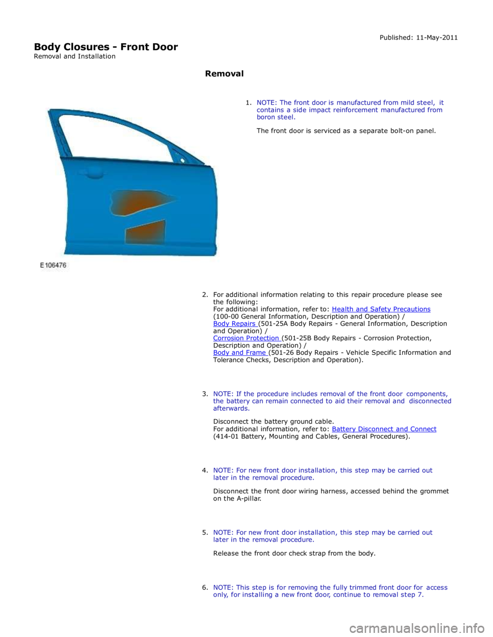
(100-00 General Information, Description and Operation) /
Body Repairs (501-25A Body Repairs - General Information, Description and Operation) /
Corrosion Protection (501-25B Body Repairs - Corrosion Protection, Description and Operation) /
Body and Frame (501-26 Body Repairs - Vehicle Specific Information and Tolerance Checks, Description and Operation).
3. NOTE: If the procedure includes removal of the front door components,
the battery can remain connected to aid their removal and disconnected
afterwards.
Disconnect the battery ground cable.
For additional information, refer to: Battery Disconnect and Connect (414-01 Battery, Mounting and Cables, General Procedures).
4. NOTE: For new front door installation, this step may be carried out
later in the removal procedure.
Disconnect the front door wiring harness, accessed behind the grommet
on the A-pillar.
5. NOTE: For new front door installation, this step may be carried out
later in the removal procedure.
Release the front door check strap from the body.
6. NOTE: This step is for removing the fully trimmed front door for access
only, for installing a new front door, continue to removal step 7.
Page 2212 of 3039
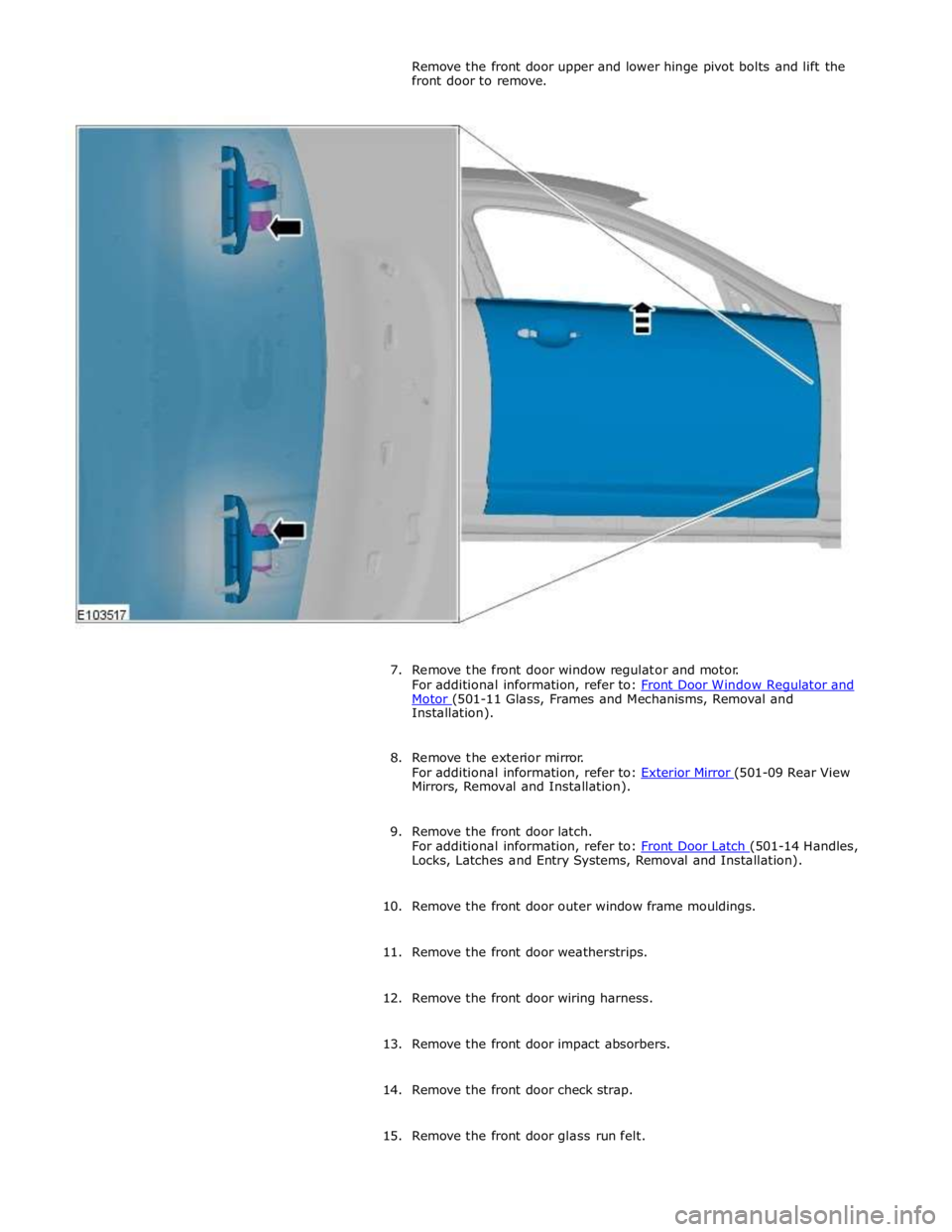
Motor (501-11 Glass, Frames and Mechanisms, Removal and Installation).
8. Remove the exterior mirror.
For additional information, refer to: Exterior Mirror (501-09 Rear View Mirrors, Removal and Installation).
9. Remove the front door latch.
For additional information, refer to: Front Door Latch (501-14 Handles, Locks, Latches and Entry Systems, Removal and Installation).
10. Remove the front door outer window frame mouldings.
11. Remove the front door weatherstrips.
12. Remove the front door wiring harness.
13. Remove the front door impact absorbers.
14. Remove the front door check strap.
15. Remove the front door glass run felt.
Page 2218 of 3039
(100-00 General Information, Description and Operation) /
Body Repairs (501-25A Body Repairs - General Information, Description and Operation) /
Corrosion Protection (501-25B Body Repairs - Corrosion Protection, Description and Operation) /
Body and Frame (501-26 Body Repairs - Vehicle Specific Information and Tolerance Checks, Description and Operation).
3. Disconnect the battery ground cable.
For additional information, refer to: Battery Disconnect and Connect (414-01 Battery, Mounting and Cables, General Procedures).
4. Remove the loadspace trim panel RH.
For additional information, refer to: Loadspace Trim Panel RH (501-05 Interior Trim and Ornamentation, Removal and Installation).
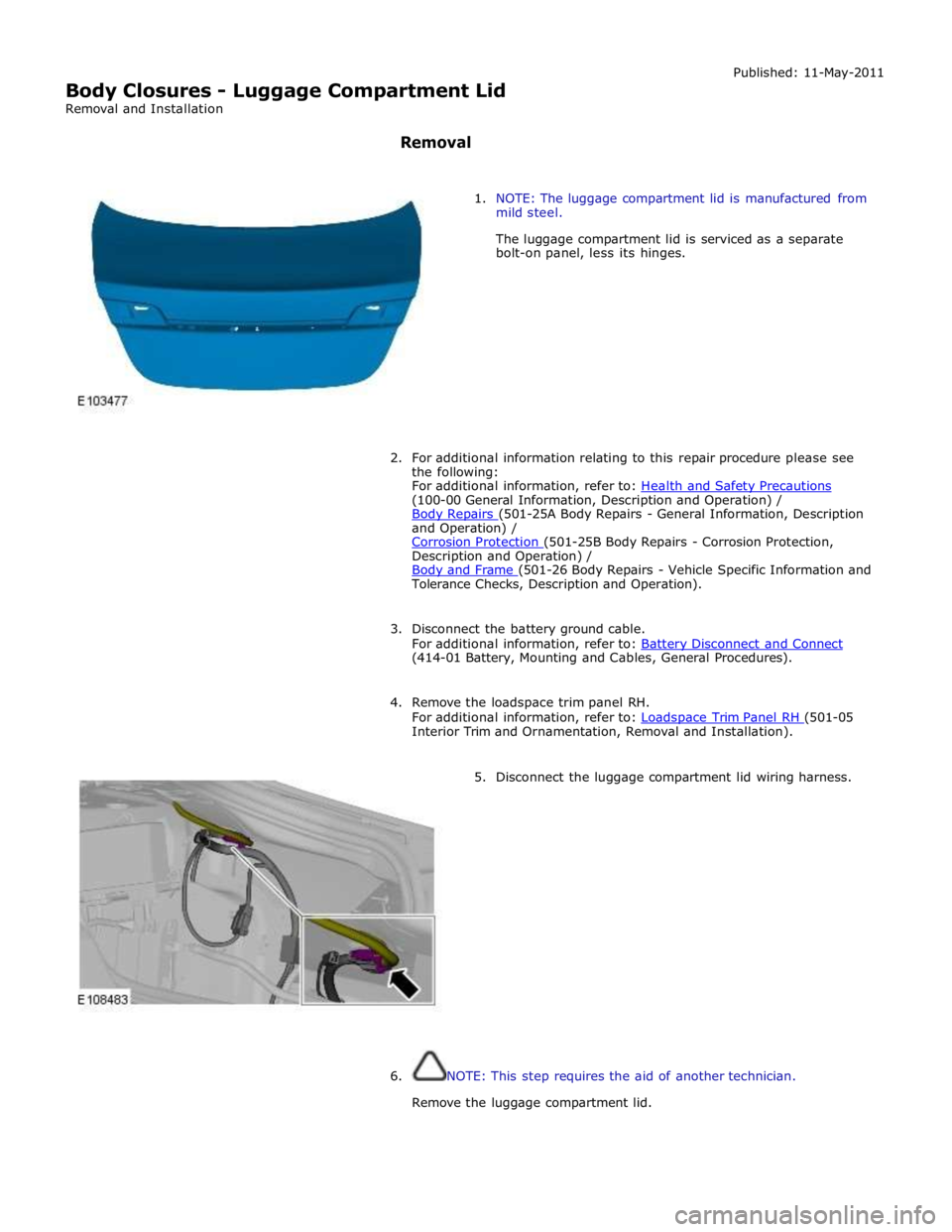
5. Disconnect the luggage compartment lid wiring harness.
6. NOTE: This step requires the aid of another technician.
Remove the luggage compartment lid.