2010 JAGUAR XFR wiring
[x] Cancel search: wiringPage 1828 of 3039
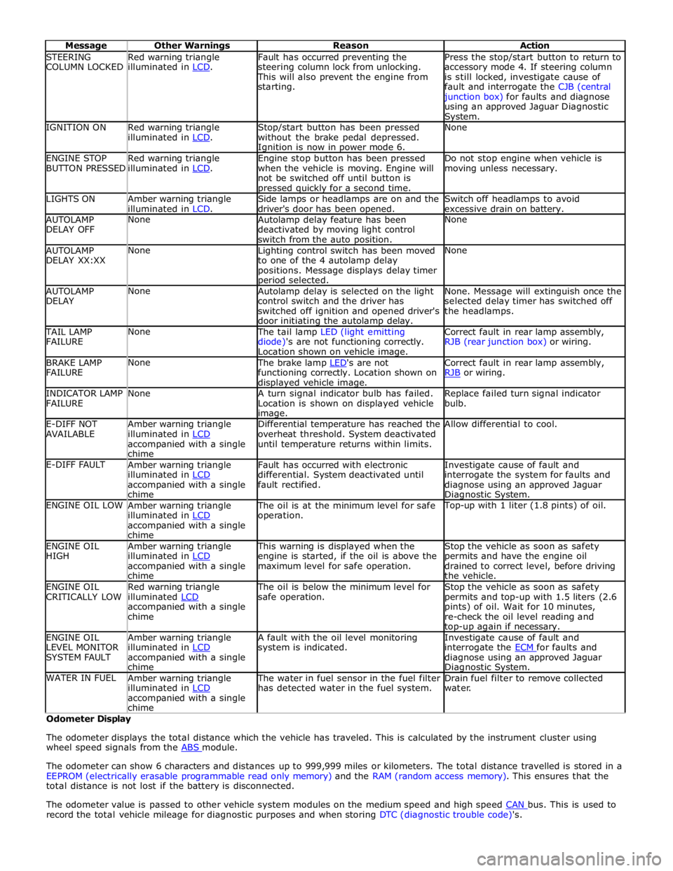
STEERING
COLUMN LOCKED Red warning triangle
illuminated in LCD. Fault has occurred preventing the
steering column lock from unlocking. This will also prevent the engine from
starting. Press the stop/start button to return to
accessory mode 4. If steering column
is still locked, investigate cause of
fault and interrogate the CJB (central junction box) for faults and diagnose
using an approved Jaguar Diagnostic System. IGNITION ON
Red warning triangle
illuminated in LCD. Stop/start button has been pressed
without the brake pedal depressed. Ignition is now in power mode 6. None ENGINE STOP
BUTTON PRESSED Red warning triangle
illuminated in LCD. Engine stop button has been pressed
when the vehicle is moving. Engine will
not be switched off until button is pressed quickly for a second time. Do not stop engine when vehicle is
moving unless necessary. LIGHTS ON
Amber warning triangle
illuminated in LCD. Side lamps or headlamps are on and the
driver's door has been opened. Switch off headlamps to avoid
excessive drain on battery. AUTOLAMP
DELAY OFF None
Autolamp delay feature has been
deactivated by moving light control
switch from the auto position. None AUTOLAMP
DELAY XX:XX None
Lighting control switch has been moved
to one of the 4 autolamp delay
positions. Message displays delay timer period selected. None AUTOLAMP
DELAY None
Autolamp delay is selected on the light
control switch and the driver has
switched off ignition and opened driver's
door initiating the autolamp delay. None. Message will extinguish once the
selected delay timer has switched off
the headlamps. TAIL LAMP
FAILURE None The tail lamp LED (light emitting
diode)'s are not functioning correctly.
Location shown on vehicle image. Correct fault in rear lamp assembly,
RJB (rear junction box) or wiring. BRAKE LAMP
FAILURE None The brake lamp LED's are not functioning correctly. Location shown on displayed vehicle image. Correct fault in rear lamp assembly,
RJB or wiring. INDICATOR LAMP
FAILURE None
A turn signal indicator bulb has failed.
Location is shown on displayed vehicle image. Replace failed turn signal indicator
bulb. E-DIFF NOT
AVAILABLE Amber warning triangle
illuminated in LCD accompanied with a single
chime Differential temperature has reached the
overheat threshold. System deactivated
until temperature returns within limits. Allow differential to cool. E-DIFF FAULT
Amber warning triangle
illuminated in LCD accompanied with a single
chime Fault has occurred with electronic
differential. System deactivated until
fault rectified. Investigate cause of fault and
interrogate the system for faults and
diagnose using an approved Jaguar Diagnostic System. ENGINE OIL LOW
Amber warning triangle
illuminated in LCD accompanied with a single
chime The oil is at the minimum level for safe
operation. Top-up with 1 liter (1.8 pints) of oil. ENGINE OIL
HIGH Amber warning triangle
illuminated in LCD accompanied with a single
chime This warning is displayed when the
engine is started, if the oil is above the
maximum level for safe operation. Stop the vehicle as soon as safety
permits and have the engine oil
drained to correct level, before driving
the vehicle. ENGINE OIL
CRITICALLY LOW Red warning triangle
illuminated LCD accompanied with a single
chime The oil is below the minimum level for
safe operation. Stop the vehicle as soon as safety
permits and top-up with 1.5 liters (2.6
pints) of oil. Wait for 10 minutes,
re-check the oil level reading and top-up again if necessary. ENGINE OIL
LEVEL MONITOR
SYSTEM FAULT Amber warning triangle
illuminated in LCD accompanied with a single
chime A fault with the oil level monitoring
system is indicated. Investigate cause of fault and
interrogate the ECM for faults and diagnose using an approved Jaguar Diagnostic System. WATER IN FUEL
Amber warning triangle
illuminated in LCD accompanied with a single
chime The water in fuel sensor in the fuel filter
has detected water in the fuel system. Drain fuel filter to remove collected
water. Odometer Display
The odometer displays the total distance which the vehicle has traveled. This is calculated by the instrument cluster using
wheel speed signals from the ABS module.
The odometer can show 6 characters and distances up to 999,999 miles or kilometers. The total distance travelled is stored in a
EEPROM (electrically erasable programmable read only memory) and the RAM (random access memory). This ensures that the
total distance is not lost if the battery is disconnected.
The odometer value is passed to other vehicle system modules on the medium speed and high speed CAN bus. This is used to record the total vehicle mileage for diagnostic purposes and when storing DTC (diagnostic trouble code)'s.
Page 1836 of 3039
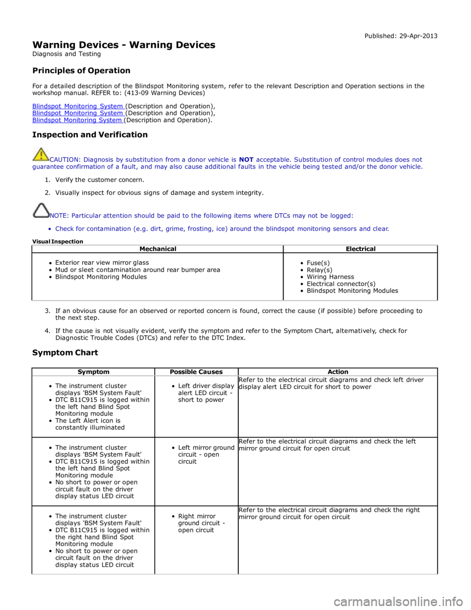
Warning Devices - Warning Devices
Diagnosis and Testing
Principles of Operation Published: 29-Apr-2013
For a detailed description of the Blindspot Monitoring system, refer to the relevant Description and Operation sections in the
workshop manual. REFER to: (413-09 Warning Devices)
Blindspot Monitoring System (Description and Operation), Blindspot Monitoring System (Description and Operation), Blindspot Monitoring System (Description and Operation).
Inspection and Verification
CAUTION: Diagnosis by substitution from a donor vehicle is NOT acceptable. Substitution of control modules does not
guarantee confirmation of a fault, and may also cause additional faults in the vehicle being tested and/or the donor vehicle.
1. Verify the customer concern.
2. Visually inspect for obvious signs of damage and system integrity.
NOTE: Particular attention should be paid to the following items where DTCs may not be logged:
Check for contamination (e.g. dirt, grime, frosting, ice) around the blindspot monitoring sensors and clear.
Visual Inspection
Mechanical Electrical
Exterior rear view mirror glass
Mud or sleet contamination around rear bumper area
Blindspot Monitoring Modules
Fuse(s)
Relay(s)
Wiring Harness
Electrical connector(s)
Blindspot Monitoring Modules
3. If an obvious cause for an observed or reported concern is found, correct the cause (if possible) before proceeding to
the next step.
4. If the cause is not visually evident, verify the symptom and refer to the Symptom Chart, alternatively, check for
Diagnostic Trouble Codes (DTCs) and refer to the DTC Index.
Symptom Chart
Symptom Possible Causes Action
The instrument cluster
displays 'BSM System Fault'
DTC B11C915 is logged within
the left hand Blind Spot
Monitoring module
The Left Alert icon is
constantly illuminated
Left driver display
alert LED circuit -
short to power Refer to the electrical circuit diagrams and check left driver
display alert LED circuit for short to power
The instrument cluster
displays 'BSM System Fault'
DTC B11C915 is logged within
the left hand Blind Spot
Monitoring module
No short to power or open
circuit fault on the driver
display status LED circuit
Left mirror ground
circuit - open
circuit Refer to the electrical circuit diagrams and check the left
mirror ground circuit for open circuit
The instrument cluster
displays 'BSM System Fault'
DTC B11C915 is logged within
the right hand Blind Spot
Monitoring module
No short to power or open
circuit fault on the driver
display status LED circuit
Right mirror
ground circuit -
open circuit Refer to the electrical circuit diagrams and check the right
mirror ground circuit for open circuit
Page 1850 of 3039
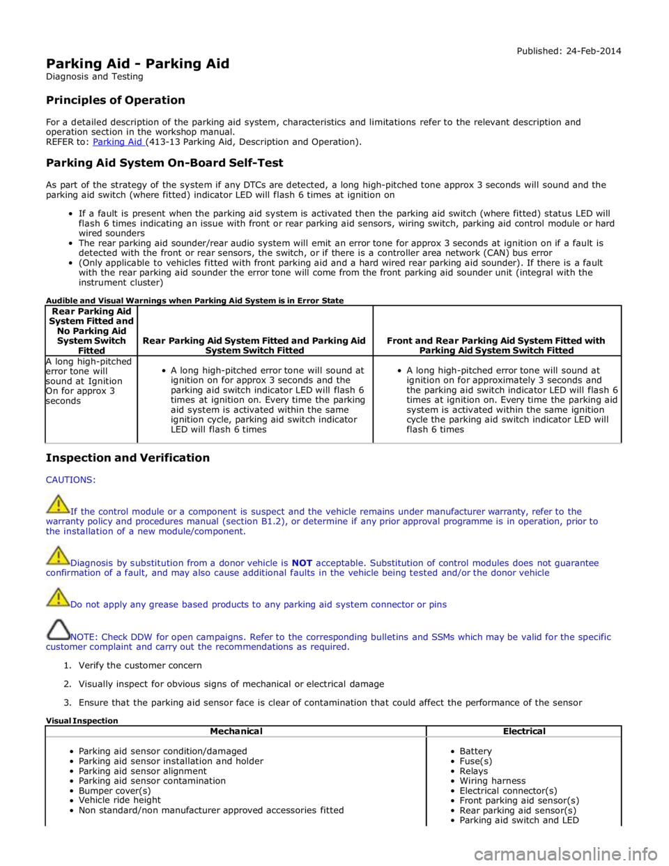
Parking Aid - Parking Aid
Diagnosis and Testing
Principles of Operation Published: 24-Feb-2014
For a detailed description of the parking aid system, characteristics and limitations refer to the relevant description and
operation section in the workshop manual.
REFER to: Parking Aid (413-13 Parking Aid, Description and Operation).
Parking Aid System On-Board Self-Test
As part of the strategy of the system if any DTCs are detected, a long high-pitched tone approx 3 seconds will sound and the
parking aid switch (where fitted) indicator LED will flash 6 times at ignition on
If a fault is present when the parking aid system is activated then the parking aid switch (where fitted) status LED will
flash 6 times indicating an issue with front or rear parking aid sensors, wiring switch, parking aid control module or hard
wired sounders
The rear parking aid sounder/rear audio system will emit an error tone for approx 3 seconds at ignition on if a fault is
detected with the front or rear sensors, the switch, or if there is a controller area network (CAN) bus error
(Only applicable to vehicles fitted with front parking aid and a hard wired rear parking aid sounder). If there is a fault
with the rear parking aid sounder the error tone will come from the front parking aid sounder unit (integral with the
instrument cluster)
Audible and Visual Warnings when Parking Aid System is in Error State
Rear Parking Aid
System Fitted and
No Parking Aid
System Switch
Fitted
Rear Parking Aid System Fitted and Parking Aid System Switch Fitted
Front and Rear Parking Aid System Fitted with Parking Aid System Switch Fitted A long high-pitched
error tone will
sound at Ignition
On for approx 3
seconds
A long high-pitched error tone will sound at
ignition on for approx 3 seconds and the
parking aid switch indicator LED will flash 6
times at ignition on. Every time the parking
aid system is activated within the same
ignition cycle, parking aid switch indicator
LED will flash 6 times
A long high-pitched error tone will sound at
ignition on for approximately 3 seconds and
the parking aid switch indicator LED will flash 6
times at ignition on. Every time the parking aid
system is activated within the same ignition
cycle the parking aid switch indicator LED will
flash 6 times Inspection and Verification
CAUTIONS:
If the control module or a component is suspect and the vehicle remains under manufacturer warranty, refer to the
warranty policy and procedures manual (section B1.2), or determine if any prior approval programme is in operation, prior to
the installation of a new module/component.
Diagnosis by substitution from a donor vehicle is NOT acceptable. Substitution of control modules does not guarantee
confirmation of a fault, and may also cause additional faults in the vehicle being tested and/or the donor vehicle
Do not apply any grease based products to any parking aid system connector or pins
NOTE: Check DDW for open campaigns. Refer to the corresponding bulletins and SSMs which may be valid for the specific
customer complaint and carry out the recommendations as required.
1. Verify the customer concern
2. Visually inspect for obvious signs of mechanical or electrical damage
3. Ensure that the parking aid sensor face is clear of contamination that could affect the performance of the sensor
Visual Inspection
Mechanical Electrical
Parking aid sensor condition/damaged
Parking aid sensor installation and holder
Parking aid sensor alignment
Parking aid sensor contamination
Bumper cover(s)
Vehicle ride height
Non standard/non manufacturer approved accessories fitted
Battery
Fuse(s)
Relays
Wiring harness
Electrical connector(s)
Front parking aid sensor(s)
Rear parking aid sensor(s)
Parking aid switch and LED
Page 1852 of 3039

Symptom Possible Causes Action Parking aid sensors are being
returned with no faults found
or signs of water
ingress/corrosion Possible issue with sensor connectors
not latched correctly
When either no/intermittent operation has been
reported the following action should be taken
1. Using Datalogger, identify the position of the
suspect parking aid sensor within the bumper
2. Visually locate the position of the suspect
parking aid sensor. Inspect and provide details in
claim if the sensor has any sign of physical
damage
3. Remove the bumper. Disconnect the wiring at
the main harness connector. Inspect the main
harness connectors and terminals for signs of
damage, backed out pins, corrosion and water
ingress, or damage to the seals. Provide details in
claim if any of the above symptoms are present
4. Attempt to remove the harness connector from
the suspect parking aid sensor without using the
connector latch i.e. lightly pull back on ALL wires
together, ensuring the harness is held close to the
back of the connector, not elsewhere on the wiring
harness. DO NOT apply excessive force. If the
connector can be removed without using the latch,
provide details in claim if connector is loose. If the
connector is fully latched, disconnect it from the
sensor
5. Inspect and provide details in claim if the
suspect sensor harness connector has any sign of
water ingress/corrosion
6. Inspect and provide details in claim if the
suspect parking aid sensor harness connector
shows any sign that the terminals have backed-out
of the connector or for any damage to the terminal
seals. Replace/repair the harness as required and
proceed
7. Remove the suspect parking aid sensor from the
bumper. Inspect the parking aid sensor connector
for signs of water ingress/corrosion. Provide details
in claim if corrosion/water ingress is present
8. Exchange the suspect parking aid sensor with
another parking aid sensor within the bumper that
is performing correctly. Reconnect all sensors and
reconnect the bumper main harness connector.
Repeat step 1. Confirm if the original fault now
appears at the new position of the suspect parking
aid sensor, if so, proceed to step 10
9. If not, carry out the appropriate open circuit and
short circuit checks between the original suspect
parking aid sensor harness connector and the
parking aid control module
10. Refit the parking aid sensors to their original
position in the bumper
11. Reconnect the parking aid sensor to the
bumper harness connector. Reconnect main harness
connector and refit the bumper
12. Repeat Step 1. If fault is still present, replace
only the faulty sensor
PINPOINT TEST A : PARKING AID SYSTEM NOT FUNCTIONING CORRECTLY WITH NO DTCS LOGGED TEST
CONDITIONS DETAILS/RESULTS/ACTIONS A1: PERMANENT FAULT 1 When the parking aid system is activated, there is a vibration on the parking aid sensor membrane. This can be verified by touching the parking aid sensor face with a hard item such as a pencil, ball-pen, small
screwdriver, or fingernail. Ensure no damage is caused to sensor painted surface Are the parking aid sensor(s) vibrating? Yes
GO to A2. No
GO to A5. A2: SENSORS VIBRATING WITH PARKING AID FAULT 1 Clean the parking aid sensor face Parking aid system functioning correctly? Yes
No further action required
No www.JagDocs.com
Page 1853 of 3039

A3: SENSORS VIBRATING WITH PARKING AID FAULT 1 Check parking aid sensors correctly mounted. Parking aid sensor holder correctly mounted. Parking aid sensor decoupler ring fitted or fitted correctly. Parking aid sensor positioning correct. Parking aid sensor
painted without being removed from the bumper assembly or not painted to manufacturer specification.
Rectify as required Parking aid system functioning correctly? Yes
No further action required
No
GO to A4. A4: SENSORS VIBRATING WITH PARKING AID FAULT 1 Carry out speaker test. Only applicable to vehicles with rear hard wired parking aid speakers. Check the parking aid speaker wiring circuit and connector. Rectify as required. Check and install a new parking aid
speaker as required. Vehicles with audio parking aid system. Confirm audio system is functioning
correctly. Refer to the relevant section of the workshop manual Parking aid system functioning correctly Yes
No further action required A5: SENSORS NOT VIBRATING WITH PARKING AID FAULT 1 Isolate the fault to front or rear parking aid sensors Are all rear parking aid sensors vibrating? Yes
GO to A6. No
GO to A10. A6: FRONT SENSORS NOT VIBRATING WITH PARKING AID FAULT 1 Check the parking aid control module is correctly configured. Check and update the car configuration file as required Parking aid system functioning correctly? Yes
No further action required
No
GO to A7. A7: FRONT SENSORS NOT VIBRATING WITH PARKING AID FAULT 1 Check the correct parking aid control module is installed to the vehicle Parking aid system functioning correctly? Yes
No further action required
No
GO to A8. A8: FRONT SENSORS NOT VIBRATING WITH PARKING AID FAULT 1 If all 4 front parking aid sensors are not vibrating, carry out harness test on common ground, power supply. Check main parking aid harness connector to bumper harness connector. Rectify as required Parking aid system functioning correctly? Yes
No further action required
No
GO to A9. A9: FRONT SENSORS NOT VIBRATING WITH PARKING AID FAULT 1 Check and install a new parking aid control module as required. Refer to the warranty policy and procedures manual, or determine if any prior approval programme is in operation, prior to the installation
of a new module/component Parking aid system functioning correctly Yes
No further action required A10: REAR SENSORS NOT VIBRATING WITH PARKING AID FAULT 1 Check the parking aid control module is correctly configured. Check and update the car configuration file as required Parking aid system functioning correctly? Yes
No further action required
No
GO to A11. A11: REAR SENSORS NOT VIBRATING WITH PARKING AID FAULT 1 If all 4 rear parking aid sensors are not vibrating, carry out harness test on common ground, power supply. Check main parking aid harness connector to bumper harness connector. Rectify as required Parking aid system functioning correctly Yes
No further action required
No
GO to A12. A12: REAR SENSORS NOT VIBRATING WITH PARKING AID FAULT 1 Check and install a new parking aid control module as required. Refer to the warranty policy and procedures manual, or determine if any prior approval programme is in operation, prior to the installation
of a new module/component
Page 1855 of 3039

Check DDW for open campaigns. Refer to the corresponding bulletins and SSMs which may be valid for the specific
customer complaint and carry out the recommendations as required.
When carrying out repair/diagnosis of the system, on removal of the front or rear bumper inspect the sensor connectors
to ensure they were correctly latched and check fly leads for signs of chaffing or trapped wires
Physical damage to the sensor (impact damage or scratched sensor surface) must NOT be changed under warranty.
DTC Description Possible Causes Action B1B36-01
Front Right Outer
Sensor - General
electrical failure
Wiring harness fault
Front Right Outer Sensor
- Component internal
failure
Refer to electrical wiring diagrams and check the
front bumper harness for damage/corrosion. Check
sensor circuit for short circuit to ground, short circuit
to power, open circuit. Repair or replace any wiring
harness as required
Check the connector for integrity and damage, then
re-connect sensor to confirm connection
Using the manufacturers approved diagnostic system
clear the DTC and run the on demand self test
If the problem persists remove the suspect sensor
from the bumper. Inspect the sensor connector for
signs of water ingress/corrosion. Exchange the
suspect sensor with another sensor within the
bumper that is not reporting a fault. Clear the DTC
and run the on demand self test to confirm if the
fault code now appears for the new position of the
suspect sensor. Renew the faulty sensor B1B36-12
Front Right Outer
Sensor - Circuit short
to battery
Wiring harness fault
Refer to electrical wiring diagrams and check the
front bumper harness for damage. Check sensor
circuit for short circuit to power. Repair or replace any
wiring harness as required
Check the connector for integrity and damage, then
re-connect sensor to confirm connection
Using the manufacturers approved diagnostic system
clear the DTC and run the on demand self test B1B36-96
Front Right Outer
Sensor - Component
internal failure
Wiring harness fault
Front Right Outer Sensor
- Component internal
failure
Refer to electrical wiring diagrams and check the
front bumper harness for damage/corrosion. Check
sensor circuit for short circuit to ground, short circuit
to power, open circuit. Repair or replace any wiring
harness as required
Check the connector for integrity and damage, then
re-connect sensor to confirm connection
Using the manufacturers approved diagnostic system
clear the DTC and run the on demand self test
If the problem persists remove the suspect sensor
from the bumper. Inspect the sensor connector for
signs of water ingress/corrosion. Exchange the
suspect sensor with another sensor within the
bumper that is not reporting a fault. Clear the DTC
and run the on demand self test to confirm if the
fault code now appears for the new position of the
suspect sensor. Renew the faulty sensor B1B38-01
Front Right Inner
Sensor - General
electrical failure
Wiring harness fault
Front Right Inner Sensor
- Component internal
failure
Refer to electrical wiring diagrams and check the
front bumper harness for damage/corrosion. Check
sensor circuit for short circuit to ground, short circuit
to power, open circuit. Repair or replace any wiring
harness as required
Check the connector for integrity and damage, then
re-connect sensor to confirm connection
Using the manufacturers approved diagnostic system
clear the DTC and run the on demand self test
If the problem persists remove the suspect sensor
from the bumper. Inspect the sensor connector for
signs of water ingress/corrosion. Exchange the
suspect sensor with another sensor within the
bumper that is not reporting a fault. Clear the DTC
and run the on demand self test to confirm if the
fault code now appears for the new position of the
suspect sensor. Renew the faulty sensor
Page 1856 of 3039
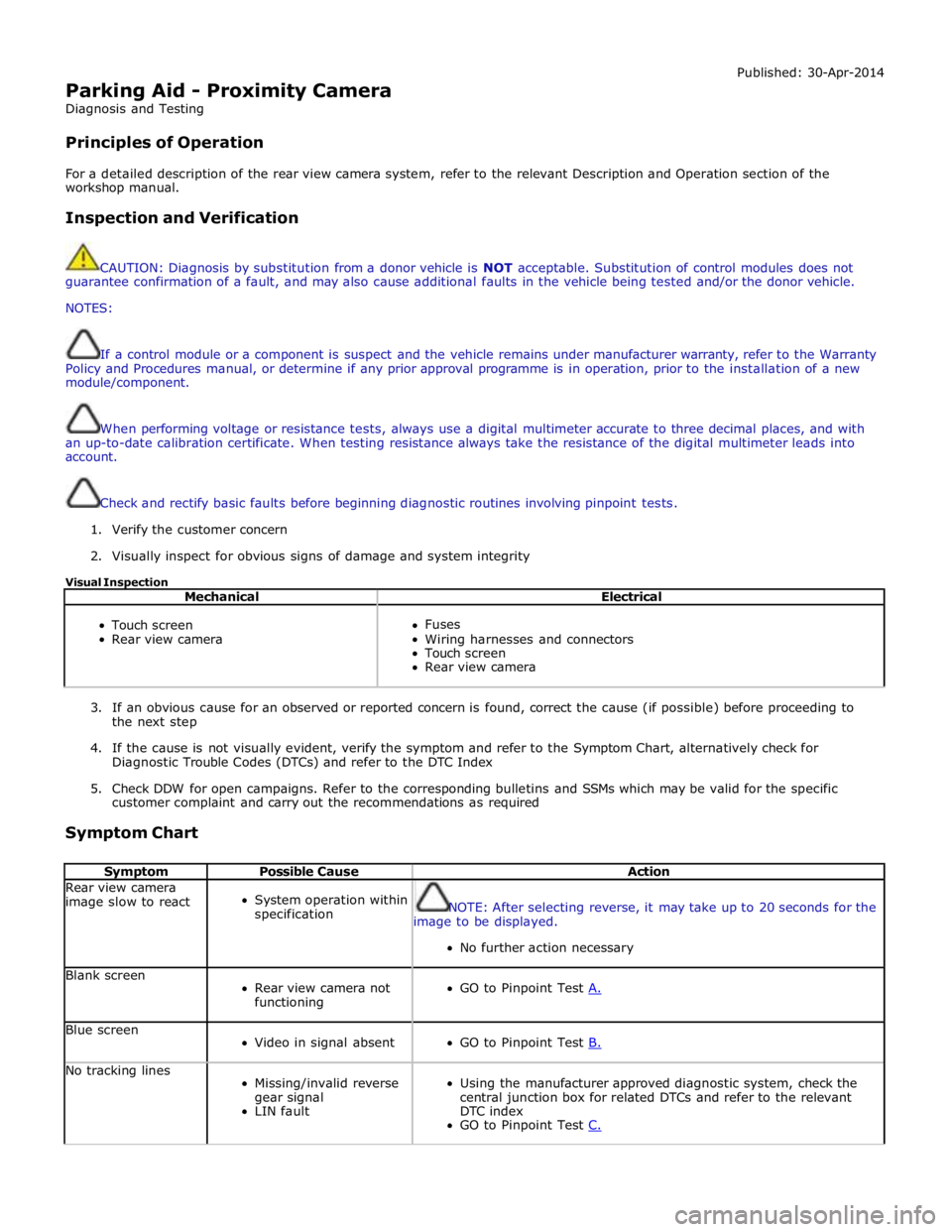
Parking Aid - Proximity Camera
Diagnosis and Testing
Principles of Operation Published: 30-Apr-2014
For a detailed description of the rear view camera system, refer to the relevant Description and Operation section of the
workshop manual.
Inspection and Verification
CAUTION: Diagnosis by substitution from a donor vehicle is NOT acceptable. Substitution of control modules does not
guarantee confirmation of a fault, and may also cause additional faults in the vehicle being tested and/or the donor vehicle.
NOTES:
If a control module or a component is suspect and the vehicle remains under manufacturer warranty, refer to the Warranty
Policy and Procedures manual, or determine if any prior approval programme is in operation, prior to the installation of a new
module/component.
When performing voltage or resistance tests, always use a digital multimeter accurate to three decimal places, and with
an up-to-date calibration certificate. When testing resistance always take the resistance of the digital multimeter leads into
account.
Check and rectify basic faults before beginning diagnostic routines involving pinpoint tests.
1. Verify the customer concern
2. Visually inspect for obvious signs of damage and system integrity
Visual Inspection
Mechanical Electrical
Touch screen
Rear view camera
Fuses
Wiring harnesses and connectors
Touch screen
Rear view camera
3. If an obvious cause for an observed or reported concern is found, correct the cause (if possible) before proceeding to
the next step
4. If the cause is not visually evident, verify the symptom and refer to the Symptom Chart, alternatively check for
Diagnostic Trouble Codes (DTCs) and refer to the DTC Index
5. Check DDW for open campaigns. Refer to the corresponding bulletins and SSMs which may be valid for the specific
customer complaint and carry out the recommendations as required
Symptom Chart
Symptom Possible Cause Action Rear view camera
image slow to react
System operation within
specification
NOTE: After selecting reverse, it may take up to 20 seconds for the
image to be displayed.
No further action necessary Blank screen
Rear view camera not
functioning
GO to Pinpoint Test A. Blue screen
Video in signal absent
GO to Pinpoint Test B. No tracking lines
Missing/invalid reverse
gear signal
LIN fault
Using the manufacturer approved diagnostic system, check the
central junction box for related DTCs and refer to the relevant
DTC index
GO to Pinpoint Test C.
Page 1886 of 3039
the secondary battery (if fitted) and passes through a grommet in the floorpan.
On new vehicles the primary battery positive terminal is fitted with a transit relay. The transit relay must removed using the
correct process detailed in the Pre Delivery Inspection (PDI) manual.
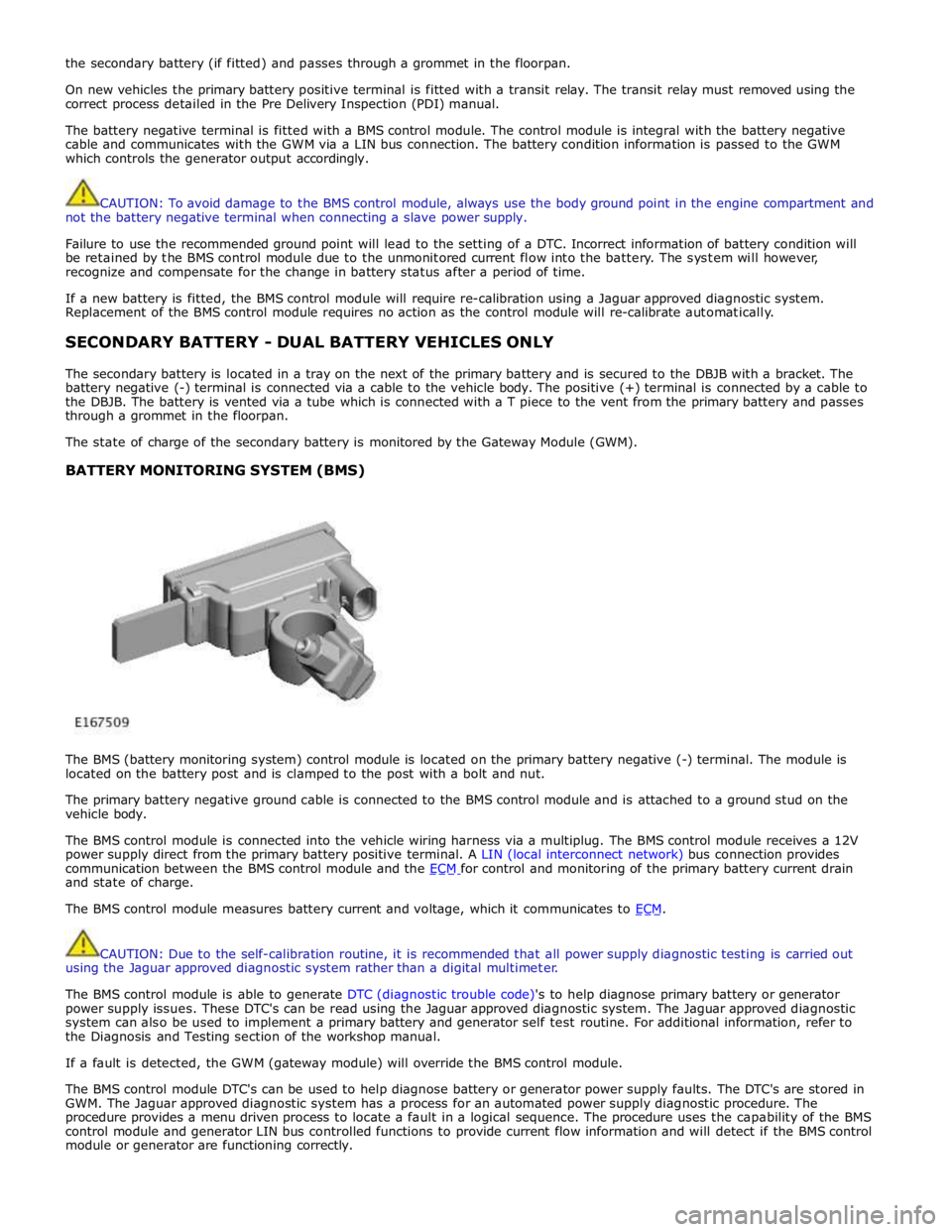
The battery negative terminal is fitted with a BMS control module. The control module is integral with the battery negative
cable and communicates with the GWM via a LIN bus connection. The battery condition information is passed to the GWM
which controls the generator output accordingly.
CAUTION: To avoid damage to the BMS control module, always use the body ground point in the engine compartment and
not the battery negative terminal when connecting a slave power supply.
Failure to use the recommended ground point will lead to the setting of a DTC. Incorrect information of battery condition will
be retained by the BMS control module due to the unmonitored current flow into the battery. The system will however,
recognize and compensate for the change in battery status after a period of time.
If a new battery is fitted, the BMS control module will require re-calibration using a Jaguar approved diagnostic system.
Replacement of the BMS control module requires no action as the control module will re-calibrate automatically.
SECONDARY BATTERY - DUAL BATTERY VEHICLES ONLY
The secondary battery is located in a tray on the next of the primary battery and is secured to the DBJB with a bracket. The
battery negative (-) terminal is connected via a cable to the vehicle body. The positive (+) terminal is connected by a cable to
the DBJB. The battery is vented via a tube which is connected with a T piece to the vent from the primary battery and passes
through a grommet in the floorpan.
The state of charge of the secondary battery is monitored by the Gateway Module (GWM).
BATTERY MONITORING SYSTEM (BMS)
The BMS (battery monitoring system) control module is located on the primary battery negative (-) terminal. The module is
located on the battery post and is clamped to the post with a bolt and nut.
The primary battery negative ground cable is connected to the BMS control module and is attached to a ground stud on the
vehicle body.
The BMS control module is connected into the vehicle wiring harness via a multiplug. The BMS control module receives a 12V
power supply direct from the primary battery positive terminal. A LIN (local interconnect network) bus connection provides
communication between the BMS control module and the ECM for control and monitoring of the primary battery current drain and state of charge.
The BMS control module measures battery current and voltage, which it communicates to ECM.
CAUTION: Due to the self-calibration routine, it is recommended that all power supply diagnostic testing is carried out
using the Jaguar approved diagnostic system rather than a digital multimeter.
The BMS control module is able to generate DTC (diagnostic trouble code)'s to help diagnose primary battery or generator
power supply issues. These DTC's can be read using the Jaguar approved diagnostic system. The Jaguar approved diagnostic
system can also be used to implement a primary battery and generator self test routine. For additional information, refer to
the Diagnosis and Testing section of the workshop manual.
If a fault is detected, the GWM (gateway module) will override the BMS control module.
The BMS control module DTC's can be used to help diagnose battery or generator power supply faults. The DTC's are stored in
GWM. The Jaguar approved diagnostic system has a process for an automated power supply diagnostic procedure. The
procedure provides a menu driven process to locate a fault in a logical sequence. The procedure uses the capability of the BMS
control module and generator LIN bus controlled functions to provide current flow information and will detect if the BMS control
module or generator are functioning correctly.