2010 JAGUAR XFR wiring
[x] Cancel search: wiringPage 1631 of 3039
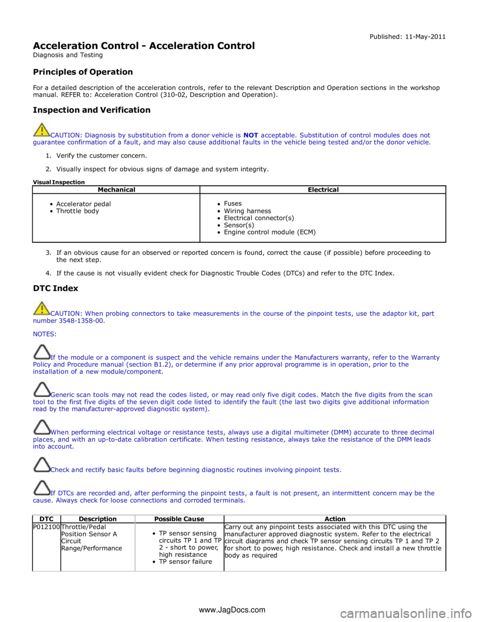
Acceleration Control - Acceleration Control
Diagnosis and Testing
Principles of Operation Published: 11-May-2011
For a detailed description of the acceleration controls, refer to the relevant Description and Operation sections in the workshop
manual. REFER to: Acceleration Control (310-02, Description and Operation).
Inspection and Verification
CAUTION: Diagnosis by substitution from a donor vehicle is NOT acceptable. Substitution of control modules does not
guarantee confirmation of a fault, and may also cause additional faults in the vehicle being tested and/or the donor vehicle.
1. Verify the customer concern.
2. Visually inspect for obvious signs of damage and system integrity.
Visual Inspection
Mechanical Electrical
Accelerator pedal
Throttle body
Fuses
Wiring harness
Electrical connector(s)
Sensor(s)
Engine control module (ECM)
3. If an obvious cause for an observed or reported concern is found, correct the cause (if possible) before proceeding to
the next step.
4. If the cause is not visually evident check for Diagnostic Trouble Codes (DTCs) and refer to the DTC Index.
DTC Index
CAUTION: When probing connectors to take measurements in the course of the pinpoint tests, use the adaptor kit, part
number 3548-1358-00.
NOTES:
If the module or a component is suspect and the vehicle remains under the Manufacturers warranty, refer to the Warranty
Policy and Procedure manual (section B1.2), or determine if any prior approval programme is in operation, prior to the
installation of a new module/component.
Generic scan tools may not read the codes listed, or may read only five digit codes. Match the five digits from the scan
tool to the first five digits of the seven digit code listed to identify the fault (the last two digits give additional information
read by the manufacturer-approved diagnostic system).
When performing electrical voltage or resistance tests, always use a digital multimeter (DMM) accurate to three decimal
places, and with an up-to-date calibration certificate. When testing resistance, always take the resistance of the DMM leads
into account.
Check and rectify basic faults before beginning diagnostic routines involving pinpoint tests.
If DTCs are recorded and, after performing the pinpoint tests, a fault is not present, an intermittent concern may be the
cause. Always check for loose connections and corroded terminals.
DTC Description Possible Cause Action P012100 Throttle/Pedal
Position Sensor A
Circuit
Range/Performance
TP sensor sensing
circuits TP 1 and TP
2 - short to power,
high resistance
TP sensor failure Carry out any pinpoint tests associated with this DTC using the
manufacturer approved diagnostic system. Refer to the electrical
circuit diagrams and check TP sensor sensing circuits TP 1 and TP 2
for short to power, high resistance. Check and install a new throttle
body as required www.JagDocs.com
Page 1646 of 3039

Published: 08-Nov-2013
Speed Control - V8 5.0L Petrol/V8 S/C 5.0L Petrol - Speed Control
Diagnosis and Testing
Principles of Operation
For a detailed description of the speed control system, refer to the relevant Description and Operation sections in the
workshop manual.
Inspection and Verification
CAUTION: Diagnosis by substitution from a donor vehicle is NOT acceptable. Substitution of control modules does not
guarantee confirmation of a fault, and may also cause additional faults in the vehicle being tested and/or the donor vehicle.
1. Verify the customer concern.
2. Visually inspect for obvious signs of damage and system integrity.
Visual Inspection
Mechanical Electrical
Speed control sensor
Ensure the speed control sensor is free from obstructions
Speed control module
Brake switch
Fuses
Wiring harness
Electrical connector(s)
Steering wheel switches
Brake switch
Speed control sensor
Speed control module
Engine Control Module (ECM)
3. If an obvious cause for an observed or reported concern is found, correct the cause (if possible) before proceeding to
the next step.
4. If the cause is not visually evident, verify the symptom and refer to the Symptom Chart, alternatively, check for
Diagnostic Trouble Codes (DTCs) and refer to the DTC Index.
Speed Control Sensor Adjustment (vehicles with adaptive system installed)
An incorrectly aligned speed control sensor can cause incorrect system operation. Before starting any repair work on the speed
control system, on vehicles with the adaptive system installed, check speed control sensor for correct vertical alignment, and
carry out speed control sensor alignment procedure using manufacturer approved diagnostic system.
Symptom Chart
Symptom Possible Causes Action Speed control inhibited or
disabled
Power or ground supply to
speed control module or speed
control sensor
Steering wheel speed control
switch/circuits
Throttle sensors
Brake switch
Anti-Lock Brake System fault
Check for DTCs that could be caused by power or
ground failure to the module or sensor and refer to
DTC Index
Check for sticking, jammed and broken speed control
switches. Refer to the electrical circuit diagrams and
check speed control switch circuits for short, open
circuit
For throttle position sensor tests. REFER to:
Electronic Engine Controls - 3.0L Diesel (303-14
Electronic Engine Controls - 3.0L Diesel, Diagnosis and
Testing),
Electronic Engine Controls - 3.0L (303-14B Electronic Engine Controls - V6 3.0L Petrol, Diagnosis and
Testing),
Electronic Engine Controls (303-14 Electronic Engine
Controls - V8 4.2L Petrol/V8 S/C 4.2L Petrol, Diagnosis
and Testing).
Check for correct installation and adjustment of brake
switch. Refer to the electrical circuit diagrams and
check brake switch circuits for short, open circuit
Check ABS system for related DTCs and refer to the
relevant DTC Index Unable to regulate/adjust
vehicle speed
Steering wheel switch
malfunction
Check for sticking, jammed and broken speed control
switches. Refer to the electrical circuit diagrams and
check speed control switch circuits for short, open
circuit
Page 1664 of 3039
Published: 11-Jul-2014
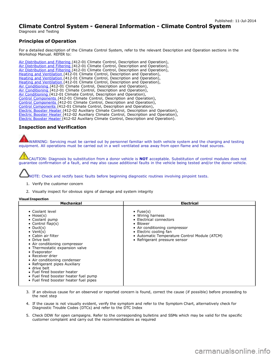
Climate Control System - General Information - Climate Control System
Diagnosis and Testing
Principles of Operation
For a detailed description of the Climate Control System, refer to the relevant Description and Operation sections in the
Workshop Manual. REFER to:
Air Distribution and Filtering (412-01 Climate Control, Description and Operation), Air Distribution and Filtering (412-01 Climate Control, Description and Operation), Air Distribution and Filtering (412-01 Climate Control, Description and Operation), Heating and Ventilation (412-01 Climate Control, Description and Operation), Heating and Ventilation (412-01 Climate Control, Description and Operation), Heating and Ventilation (412-01 Climate Control, Description and Operation), Air Conditioning (412-01 Climate Control, Description and Operation), Air Conditioning (412-01 Climate Control, Description and Operation), Air Conditioning (412-01 Climate Control, Description and Operation), Control Components (412-01 Climate Control, Description and Operation), Control Components (412-01 Climate Control, Description and Operation), Control Components (412-01 Climate Control, Description and Operation), Electric Booster Heater (412-02 Auxiliary Climate Control, Description and Operation), Electric Booster Heater (412-02 Auxiliary Climate Control, Description and Operation), Electric Booster Heater (412-02 Auxiliary Climate Control, Description and Operation).
Inspection and Verification
WARNING: Servicing must be carried out by personnel familiar with both vehicle system and the charging and testing
equipment. All operations must be carried out in a well ventilated area away from open flame and heat sources.
CAUTION: Diagnosis by substitution from a donor vehicle is NOT acceptable. Substitution of control modules does not
guarantee confirmation of a fault, and may also cause additional faults in the vehicle being tested and/or the donor vehicle.
NOTE: Check and rectify basic faults before beginning diagnostic routines involving pinpoint tests.
1. Verify the customer concern
2. Visually inspect for obvious signs of damage and system integrity
Visual Inspection
Mechanical Electrical
Coolant level
Hose(s)
Coolant pump
Control flap(s)
Duct(s)
Vent(s)
Cabin air filter
Drive belt
Air conditioning compressor
Thermostatic expansion valve
Evaporator
Receiver drier
Air conditioning condenser
Refrigerant pipes Auxiliary
drive belt
Fuel fired booster heater
Fuel fired booster heater fuel pump
Fuel fired booster heater fuel pipes
Fuse(s)
Wiring harness
Electrical connectors
Blower
Air conditioning compressor
Electric cooling fan
Automatic Temperature Control Module (ATCM)
Refrigerant pressure sensor
3. If an obvious cause for an observed or reported concern is found, correct the cause (if possible) before proceeding to
the next step
4. If the cause is not visually evident, verify the symptom and refer to the Symptom Chart, alternatively check for
Diagnostic Trouble Codes (DTCs) and refer to the DTC Index
5. Check DDW for open campaigns. Refer to the corresponding bulletins and SSMs which may be valid for the specific
customer complaint and carry out the recommendations as required
Page 1712 of 3039
bus. Temperature control for the heater element is provided by the steering wheel heater control module which receives a
temperature feedback signal from a NTC (negative temperature coefficient) thermistor located within the steering wheel.
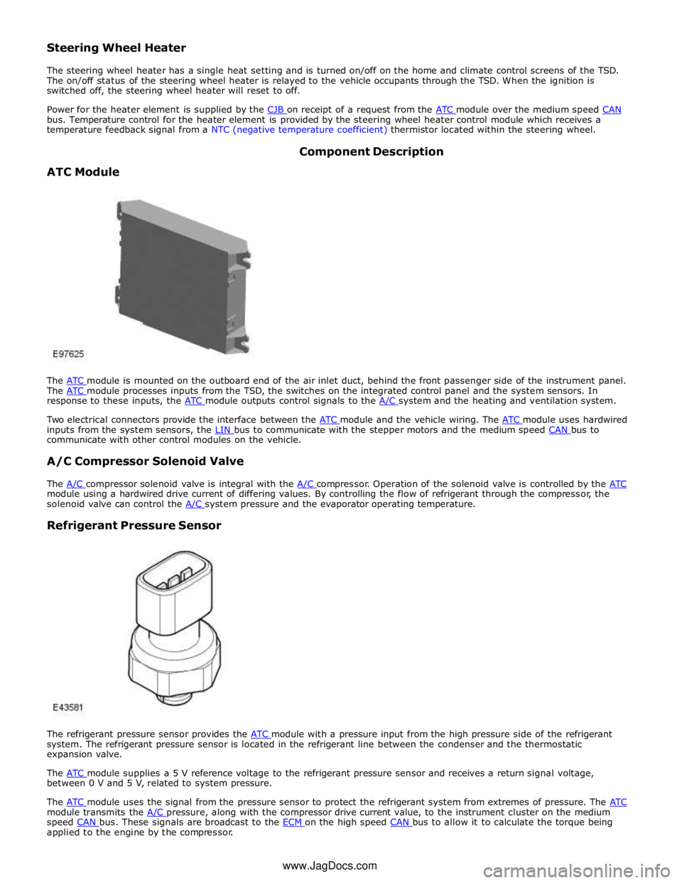
ATC Module Component Description
The ATC module is mounted on the outboard end of the air inlet duct, behind the front passenger side of the instrument panel. The ATC module processes inputs from the TSD, the switches on the integrated control panel and the system sensors. In response to these inputs, the ATC module outputs control signals to the A/C system and the heating and ventilation system.
Two electrical connectors provide the interface between the ATC module and the vehicle wiring. The ATC module uses hardwired inputs from the system sensors, the LIN bus to communicate with the stepper motors and the medium speed CAN bus to communicate with other control modules on the vehicle.
A/C Compressor Solenoid Valve
The A/C compressor solenoid valve is integral with the A/C compressor. Operation of the solenoid valve is controlled by the ATC module using a hardwired drive current of differing values. By controlling the flow of refrigerant through the compressor, the
solenoid valve can control the A/C system pressure and the evaporator operating temperature.
Refrigerant Pressure Sensor
The refrigerant pressure sensor provides the ATC module with a pressure input from the high pressure side of the refrigerant system. The refrigerant pressure sensor is located in the refrigerant line between the condenser and the thermostatic
expansion valve.
The ATC module supplies a 5 V reference voltage to the refrigerant pressure sensor and receives a return signal voltage, between 0 V and 5 V, related to system pressure.
The ATC module uses the signal from the pressure sensor to protect the refrigerant system from extremes of pressure. The ATC module transmits the A/C pressure, along with the compressor drive current value, to the instrument cluster on the medium speed CAN bus. These signals are broadcast to the ECM on the high speed CAN bus to allow it to calculate the torque being applied to the engine by the compressor. www.JagDocs.com
Page 1744 of 3039
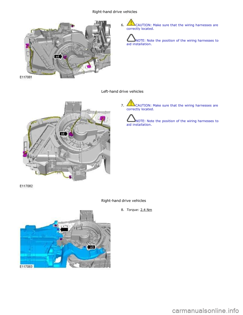
6. CAUTION: Make sure that the wiring harnesses are
correctly located.
NOTE: Note the position of the wiring harnesses to
aid installation.
Left-hand drive vehicles
7. CAUTION: Make sure that the wiring harnesses are
correctly located.
NOTE: Note the position of the wiring harnesses to
aid installation.
Right-hand drive vehicles
8. Torque: 2.4 Nm
Right-handdrivevehicles
Page 1791 of 3039
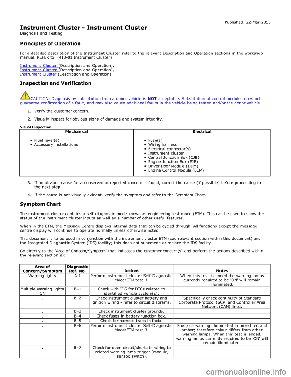
Instrument Cluster - Instrument Cluster
Diagnosis and Testing
Principles of Operation Published: 22-Mar-2013
For a detailed description of the Instrument Cluster, refer to the relevant Description and Operation sections in the workshop
manual. REFER to: (413-01 Instrument Cluster)
Instrument Cluster (Description and Operation), Instrument Cluster (Description and Operation), Instrument Cluster (Description and Operation).
Inspection and Verification
CAUTION: Diagnosis by substitution from a donor vehicle is NOT acceptable. Substitution of control modules does not
guarantee confirmation of a fault, and may also cause additional faults in the vehicle being tested and/or the donor vehicle.
1. Verify the customer concern.
2. Visually inspect for obvious signs of damage and system integrity.
Visual Inspection
Mechanical Electrical
Fluid level(s)
Accessory installations
Fuse(s)
Wiring harness
Electrical connector(s)
Instrument cluster
Central Junction Box (CJB)
Engine Junction Box (EJB)
Driver Door Module (DDM)
Engine Control Module (ECM)
3. If an obvious cause for an observed or reported concern is found, correct the cause (if possible) before proceeding to
the next step.
4. If the cause is not visually evident, verify the symptom and refer to the Symptom Chart.
Symptom Chart
The instrument cluster contains a self-diagnostic mode known as engineering test mode (ETM). This can be used to show the
status of the instrument cluster inputs as well as a number of other useful features.
When in the ETM, the Message Centre displays internal data that can be cycled through. All functions except the message
centre display will continue to operate normally unless otherwise noted.
This document is to be used in conjunction with the instrument cluster ETM (see relevant section within this document) and
the Integrated Diagnostic System (IDS) facility; this does not supersede or replace the IDS facility.
Go directly to the 'Area of Concern/Symptom' that indicates the customer concern(s) and perform the actions described within
the relevant section(s):
Area of Concern/Symptom Diagnostic
Ref. No.
Actions
Notes Warning lights A-1
Perform instrument cluster Self-Diagnostic
Mode/ETM test 3. When this test is ended the warning lamps
currently required to be 'ON' will remain
illuminated. Multiple warning lights
'ON' B–1
Check with IDS for DTCs related to
identified vehicle system(s). . . B–2
Check instrument cluster battery and
ignition wiring - refer to circuit diagrams. Specifically check continuity of Standard
Corporate Protocol (SCP) and Controller Area
Network (CAN) lines. . B–3 Check instrument cluster grounds. . . B–4 Check fuses in battery junction box. . . B–5 Check for harness traps in facia. . . B–6
Perform instrument cluster Self-Diagnostic
Mode/ETM test 3. Frost/ice warning illuminated in mixed red and
amber; therefore colour differs from other
warning lamps. When this test is ended,
warning lamps currently required to be 'ON' will
remain illuminated. . B–7
Check for open circuit/shorts in wiring to
related warning lamp trigger (module,
sensor, switch). .
Page 1792 of 3039

Specific warning lamp
'ON' C–1
Check with IDS for DTCs related to
identified vehicle system. . . C–2
Check for open circuit/shorts in wiring
related to warning lamp circuit (module,
sensor, switch) where appropriate. . . C–3
Perform cluster Self-Diagnostic Mode/ETM
test 3. Frost/ice warning illuminated in mixed red and
amber; therefore colour differs from other
warning lamps. When this test is ended,
warning lamps currently required to be 'ON' will
remain illuminated. . C–4
Check the specific vehicle system
indicated by the warning lamp
illuminated? What is the warning lamp telling me? Does this
check out with the DTC logged by the system indicating the fault? Fuel gauge operation D–1
Perform Self-Diagnostic Mode/ETM test 21
to establish if fuel level input to cluster is
out of range or invalid. 0 - 9 = short circuit; gauge will show empty. 10
– 254 = normal range. 255 = open circuit;
gauge will show empty. --- = missing signal; gauge will show empty. . D–2
Check gauge function versus
Self-Diagnostic Mode/ETM test 21. 0 = empty, 254 = full. 255 = invalid; gauge will
show empty. . D–3
Check for open circuit/shorts in wiring
between the Fuel Delivery Module, Jet
Pump Module and Rear Electronic Module (REM). . Fuel gauge reading E–1
Check gauge position versus
Self-Diagnostic Mode/ETM test 21. 0 = empty to 254 = full (255 invalid; gauge will
show empty). Other values percentage of above range e.g. 127 = half. . E–2
Calculate percentage fuel level from figure
obtained from Self-Diagnostic Mode/ETM
test 21 and compare to IDS vehicle fuel percentage test. Self-Diagnostic Mode fuel level percentage can
be calculated as follows: Value from
Self-Diagnostic Mode test 26 ÷ 254 x 100 = %
shown on gauge. . E–3
Monitor value of Self-Diagnostic Mode
test/ETM test 21 (during test drive) to
establish if input drops out of range. 0 - 9 = short circuit; gauge will show empty. 10
– 254 = normal range. 255 = open circuit;
gauge will show empty. --- = missing signal; gauge will show empty. . E–4
Monitor 'FUEL LEVEL' in IDS data logger
(during test drive) to correlate gauge position to vehicle reported fuel level. Gauge function is damped so will not follow
rapidly changing Fuel Delivery Module values. Speedometer
operation H–1
Monitor Self-Diagnostic Mode/ETM test 19
(during test drive) check to establish if
vehicle speed input to cluster is out of range or invalid. Display speed input in 1/10 mile/h, no decimal
point shown, and is compensated for tire size
etc. Displays ---- or INV if message is not
received or if received data is invalid. Speedometer reading I–1
During test drive compare speedometer
position to Self-Diagnostic Mode/ETM test
19, displayed value. Self-Diagnostic Mode displayed speed figure will
be approx 3% higher than speed indicated by
speedometer. Allowed tolerance – minus nothing/+ 10% + 2.5 mile/h. . I–2
Monitor Self-Diagnostic Mode/ETM test 19
(during test drive) to establish if vehicle
speed input to cluster drops out of range
or is invalid. Displays ---- if message is not received or if
received data is invalid for two seconds or more. . I–3
Check that installed wheels and tires are
standard Jaguar fitment. Confirm wheel
size in IDS, 'ADD REMOVE ACCESSORY'
section. Non standard wheels and tires may lead to
speed indication inaccuracies. Incorrectly set
wheel size will result in speed indication
inaccuracies. Trip and odometer distance
accumulation will also be incorrect. Tachometer operation J–1
Perform Self-Diagnostic Mode/ETM test 20
to establish if vehicle rpm input to cluster
out of range or invalid. Displays ---- or INV if message is not received
or if received data is invalid. Tachometer reading K–1
Check tachometer position versus
Self-Diagnostic Mode/ETM test 20, displayed value. Tachometer accuracy +/- 100 rpm. . K–2
Monitor 'ENGINE RPM' in IDS data logger
at constant engine rpm to compare
tachometer indicated engine rpm to
engine rpm reported by Engine Control
Module (ECM). Tachometer accuracy +/- 100 rpm. . K–3
Monitor Self-Diagnostic Mode test/ETM
test 20, (during test drive) to establish if
input to cluster drops out of range or is
invalid. Displays ---- or INV if message is not received
or if received data is invalid. Gauge judder L–1
Perform Self-Diagnostic Mode test/ETM
test 2, to prove out smooth gauge operation. . Gauge noise M–1
Perform vehicle road test. Gauges should
not be audible during operation in drive cycle. . www.JagDocs.com
Page 1793 of 3039

. M–2
Benchmark noise against non-complaint
vehicle. . Trip (fuel) computer N–1
Check for consistent display (during test
drive) of valid 'Rolling Odometer' count in
Self-Diagnostic Mode/ETM test 24. Displays ---- , INV or 255 if message is not
received, or if received data is invalid. . N–2
Check that installed wheels and tires are
standard Jaguar fit. Confirm fitted wheel
size in IDS, 'ADD REMOVE ACCESSORY'
section. Non standard wheels and tires or incorrectly set
wheel size may lead to Odometer increment
inaccuracies. This will impact the distance
accumulators, which in turn affects the rolling
average, fuel economy and range values. Trip
distance accumulation will also be incorrect. . N–3
Consider noting odometer value and
resetting fuel computer system. Advise
customer to conduct brim-to-brim fuel
tank test. Use collected information to
determine if system accurate. . Column adjust O-1
Check with IDS for DTCs related to powered column system. . O-2
Check cluster battery supply voltage and
ground resistance. Check for loose
connections. . O-3
Check power column motors supply voltage. . O-4
Check power column switch for physical damage. . Passive Anti-Theft
System (PATS)
indicator P–1
Check for three second prove out when
vehicle start button is pressed. . . P–2
Check for loose connections/wiring continuity. . . P–3 Check ignition switch for physical damage. . Cluster illumination Q–1
Check for loose connections/wiring continuity. . . Q–2 Check dimmer switch operation. . Cluster backlight operation R–1
Is the backlight on other components inoperative. . . R–2 Check dimmer switch operation. . . R–3
Check for loose connections/wiring continuity. . Chime/tone operation S–1 Check vehicle configuration. . . S–2
Utilize lights ON, ignition OFF, door open warning to verify chime operation. . . S–3 Check appropriate sensing circuit. . Continuous chime/tone T–1 Check appropriate sensing circuit. . Unexpected chime operation U–1 Check vehicle configuration. . Message centre display illumination V–1
Is the backlight 'ON' and other components dim? . . V–2
Does the lighting level of other
components change when dimmer adjusted? . Message centre
display issue W–1
Perform Self-Diagnostic Mode test/ETM
tests 5 to 9, to prove out LCD display
function. . Message centre
missing lines X–1
Perform Self-Diagnostic Mode test/ETM
tests 5 to 9, to prove out LCD display
function. . Message centre
incorrect message Y–1 What is the message? . . Y–2
Check for open circuit/shorts in wiring to
related warning light trigger (module,
sensor, switch). . Cluster/connectivity Z–1 Check cluster battery and ignition wiring. . . Z–2 Check cluster grounds. . . Z–3 Disconnect/reconnect cluster. . . Z–4
Attempt to enter Self-Diagnostic
Mode/ETM to prove cluster response to inputs. . No crank AA–1
Check with IDS for presence of related
DTCs. . . AA–2
Is there a Passive Anti-Theft System (PATS) flash code? . . AA–3
Does the vehicle crank with the other passive key? .