2010 JAGUAR XFR length
[x] Cancel search: lengthPage 10 of 3039

211-05: Steering Column Switches
Description and OperationComponent Location
Overview
System Operation and Component DescriptionDiagnosis and TestingSteering Column SwitchesRemoval and InstallationHazard Flasher Switch
Steering Column Multifunction Switch LH
Steering Column Multifunction Switch RH
Steering Column Lock Actuator3: Powertrain
303: Engine
303-00: Engine System - General Information
Diagnosis and TestingEngine - 5.0LGeneral ProceduresBearing Inspection
Camshaft Bearing Journal Diameter
Camshaft End Play
Camshaft Lobe Lift
Camshaft Surface Inspection
Connecting Rod Cleaning
Connecting Rod Large End Bore
Crankshaft End Play
Cylinder Bore Out-of-Round
Exhaust Manifold Cleaning and Inspection
Leakage Test Using Smoke Test Equipment
Piston Inspection
Piston Pin Diameter
Piston Pin to Bore Diameter
Piston Ring End Gap
Piston Ring-to-Groove Clearance
Valve Spring Free Length
Valve Stem Diameter
Cylinder Head Distortion
Cylinder Compression Test - V8 S/C 5.0L Petrol303-01D: Engine - V8 S/C 5.0L PetrolSpecificationDescription and OperationComponent Location
Page 92 of 3039

1
Measure the current using a digital multimeter 2
Measure the voltage using a digital multimeter 3
Measure the resistance using a digital multimeter 4
Measure the length/distance 5
Check that the specified pressure is available using a suitable pressure gauge
Page 395 of 3039

the aluminum wheel knuckle via an integral ball-joint.
Lower Control Arm
The aluminum lower arm locates to the subframe via one cross-axis joint and one plain rubber bush, and to the wheel knuckle
via a second plain rubber bush.
The rear of the control arm has mounting points for the damper and the stabilizer link.
Toe-Link
The toe-link is located between the wheel knuckle and brackets on the subframe.
The toe-link comprises an inner rod with integral axial ball joint. The inner ball joint has a threaded spigot which locates in a
bracket on the subframe and is secured with a locknut. The rod has an internal thread which accepts the outer rod.
The outer rod has a cross-axis joint at its outer end which is located in a clevis on the wheel knuckle, and is secured with a
bolt and locknut.
The length of the toe-link can be adjusted by rotating the inner rod. This allows for adjustment of the toe angle for the rear
wheel. Once set the inner rod can be locked in position by tightening a locknut on the outer rod against the inner rod.
Wheel Knuckle
The cast aluminum wheel knuckle attaches to:
the upper control arm via a ball-joint located in the arm,
the lower control arm via a plain rubber bush located in the arm,
the toe-link via a cross-axis joint located in the toe link.
The wheel knuckle also provides the mounting locations for the:
wheel hub assembly,
wheel bearing,
wheel speed sensor,
brake caliper,
and disc shield.
Stabilizer Bar
The solid construction stabilizer bar and bushes have been designed to provide particular characteristics in maintaining roll
rates, specifically in primary ride comfort. There are six derivatives of rear stabilizer bar, with different diameters, to support
the various powertrains:
V6 gasoline - 12.7 mm solid bar
V8 4.2L and 5.0L gasoline - 13.6 mm solid bar
V6 2.7L diesel -14.5 mm solid bar
V6 3.0L diesel - 14.5 mm solid bar
V6 3.0L diesel with Adaptive Damping – 16mm tubular
V8 4.2L gasoline supercharged – 16mm tubular
V8 5.0L gasoline supercharged
- SV8 - 17mm tubular
- XFR - 18mm tubular
The stabilizer bar is attached to the top of the subframe with two bushes and mounting brackets. The stabilizer bar has
crimped, 'anti-shuffle' collars pressed in position on the inside edges of the bushes. The collars prevent sideways movement of
the stabilizer bar.
Each end of the stabilizer bar curves rearward to attach to a ball joint on each stabilizer link. Each link is attached via a
second ball joint to a cast bracket on the lower control arm. The links allow the stabilizer bar to move with the wheel travel
providing maximum effectiveness.
Spring and Damper Assembly
The spring and damper assembly are attached to cast brackets on the lower control arms and to the vehicle body by four studs
secured by locking nuts. Dependant on vehicle model there are three types of coil spring and damper available:
a standard oil passive damper (All models except supercharged),
an adaptive damper, also known as Computer Active Technology Suspension (CATS) on 4.2L supercharged vehicles up to
2010MY, For additional information refer to Vehicle Dynamic Suspension 4.2L.
a continuously variable adaptive damper, also known as Adaptive Dynamics System on 5.0L supercharged vehicles from
2010MY. For additional information refer to Vehicle Dynamic Suspension 5.0L.
The dampers are a monotube design with a spring located by a circlip onto the damper tube. The lower end of the damper has
a spherical joint which locates in the lower control arm and is secured with a bolt.
The damper piston is connected to a damper rod which is sealed at its exit point from the damper body. The threaded outer
end of the damper rod locates through a hole in the top mount. A self locking nut secures the top mount to the damper rod.
The damper rod on the adaptive damper has an electrical connector on the outer end of the damper rod. www.JagDocs.com
Page 562 of 3039

Rear Drive Halfshafts - Rear Drive Halfshafts - Overview
Description and Operation
Overview Published: 11-May-2011
The CV (constant velocity) joint at each end of the halfshafts meets the angle change requirements due to suspension
deflection. The plunge capability of the CV joint accommodates the length change.
Page 563 of 3039

Published: 11-May-2011
Rear Drive Halfshafts - Rear Drive Halfshafts - System Operation and
Component Description
Description and Operation
System Operation
Rear Drive Halfshafts Component Description
The solid-steel halfshafts are of unequal length, with each halfshaft comprising inner and outer CV (constant velocity) joints.
The CV joints are the 'ball and socket' type packed with grease and protected by gaiters.
The outer CV joint is an interference fit into the wheel hub and secured by a locking nut. The inner CV joint is a slide fit and is
retained in the differential with a spring clip.
www.JagDocs.com
Page 782 of 3039

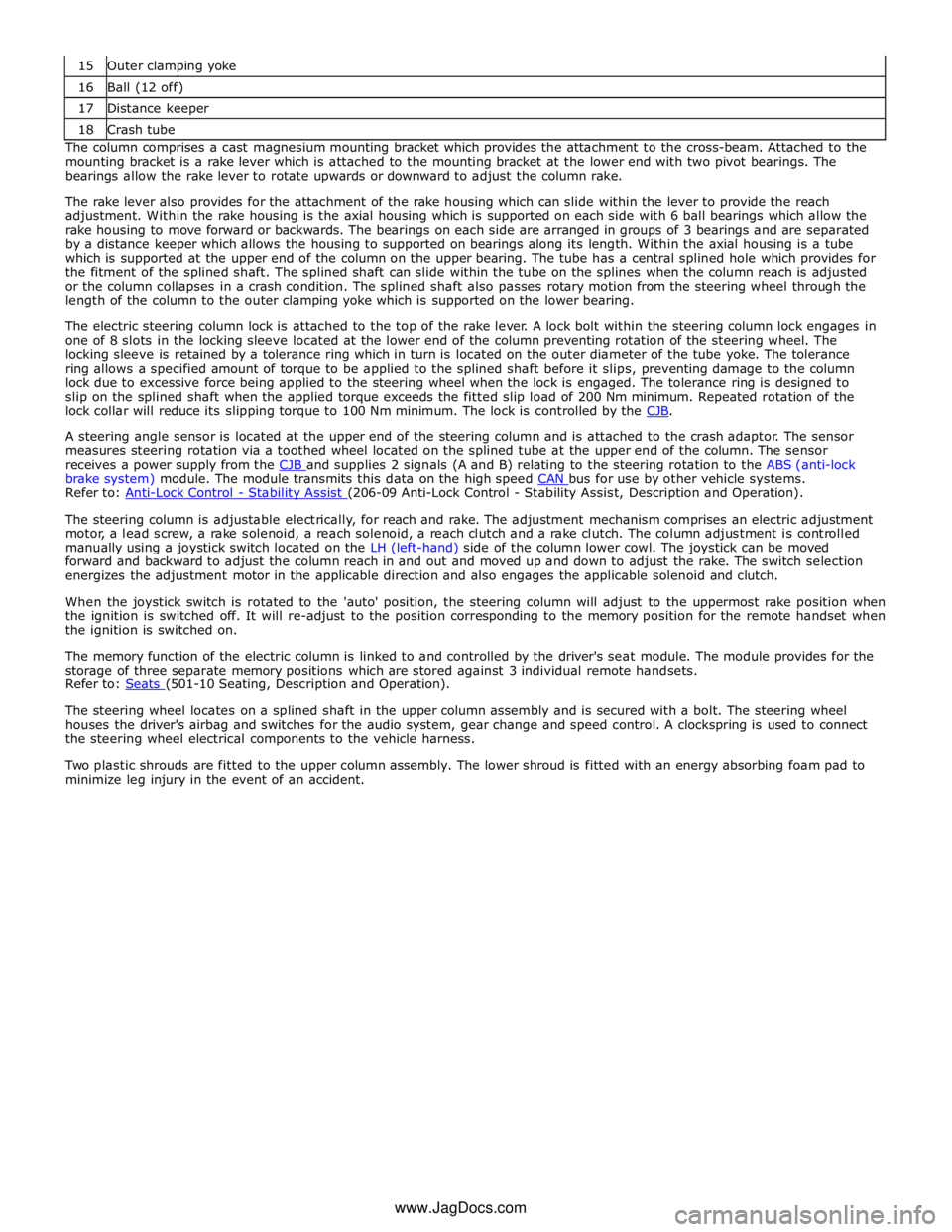
16 Ball (12 off) 17 Distance keeper 18 Crash tube The column comprises a cast magnesium mounting bracket which provides the attachment to the cross-beam. Attached to the
mounting bracket is a rake lever which is attached to the mounting bracket at the lower end with two pivot bearings. The
bearings allow the rake lever to rotate upwards or downward to adjust the column rake.
The rake lever also provides for the attachment of the rake housing which can slide within the lever to provide the reach
adjustment. Within the rake housing is the axial housing which is supported on each side with 6 ball bearings which allow the
rake housing to move forward or backwards. The bearings on each side are arranged in groups of 3 bearings and are separated
by a distance keeper which allows the housing to supported on bearings along its length. Within the axial housing is a tube
which is supported at the upper end of the column on the upper bearing. The tube has a central splined hole which provides for
the fitment of the splined shaft. The splined shaft can slide within the tube on the splines when the column reach is adjusted
or the column collapses in a crash condition. The splined shaft also passes rotary motion from the steering wheel through the
length of the column to the outer clamping yoke which is supported on the lower bearing.
The electric steering column lock is attached to the top of the rake lever. A lock bolt within the steering column lock engages in
one of 8 slots in the locking sleeve located at the lower end of the column preventing rotation of the steering wheel. The
locking sleeve is retained by a tolerance ring which in turn is located on the outer diameter of the tube yoke. The tolerance
ring allows a specified amount of torque to be applied to the splined shaft before it slips, preventing damage to the column
lock due to excessive force being applied to the steering wheel when the lock is engaged. The tolerance ring is designed to
slip on the splined shaft when the applied torque exceeds the fitted slip load of 200 Nm minimum. Repeated rotation of the
lock collar will reduce its slipping torque to 100 Nm minimum. The lock is controlled by the CJB.
A steering angle sensor is located at the upper end of the steering column and is attached to the crash adaptor. The sensor
measures steering rotation via a toothed wheel located on the splined tube at the upper end of the column. The sensor
receives a power supply from the CJB and supplies 2 signals (A and B) relating to the steering rotation to the ABS (anti-lock brake system) module. The module transmits this data on the high speed CAN bus for use by other vehicle systems. Refer to: Anti-Lock Control - Stability Assist (206-09 Anti-Lock Control - Stability Assist, Description and Operation).
The steering column is adjustable electrically, for reach and rake. The adjustment mechanism comprises an electric adjustment
motor, a lead screw, a rake solenoid, a reach solenoid, a reach clutch and a rake clutch. The column adjustment is controlled
manually using a joystick switch located on the LH (left-hand) side of the column lower cowl. The joystick can be moved
forward and backward to adjust the column reach in and out and moved up and down to adjust the rake. The switch selection
energizes the adjustment motor in the applicable direction and also engages the applicable solenoid and clutch.
When the joystick switch is rotated to the 'auto' position, the steering column will adjust to the uppermost rake position when
the ignition is switched off. It will re-adjust to the position corresponding to the memory position for the remote handset when
the ignition is switched on.
The memory function of the electric column is linked to and controlled by the driver's seat module. The module provides for the
storage of three separate memory positions which are stored against 3 individual remote handsets.
Refer to: Seats (501-10 Seating, Description and Operation).
The steering wheel locates on a splined shaft in the upper column assembly and is secured with a bolt. The steering wheel
houses the driver's airbag and switches for the audio system, gear change and speed control. A clockspring is used to connect
the steering wheel electrical components to the vehicle harness.
Two plastic shrouds are fitted to the upper column assembly. The lower shroud is fitted with an energy absorbing foam pad to
minimize leg injury in the event of an accident.
www.JagDocs.com
Page 844 of 3039

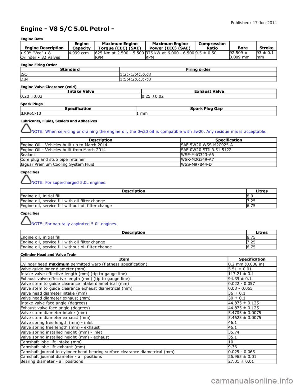
Engine - V8 S/C 5.0L Petrol -
Engine Data Published: 17-Jun-2014
Engine Description Engine Capacity Maximum Engine Torque (EEC) (SAE) Maximum Engine
Power (EEC) (SAE) Compression
Ratio
Bore
Stroke • 90° "Vee" • 8 Cylinder • 32 Valves 4.999 ccm
625 Nm at 2.500 - 5.500
RPM 375 kW at 6.000 - 6.500
RPM 9.5 ± 0.50 92.509 ±
0.009 mm 93 ± 0.1
mm Engine Firing Order
Standard Firing order ISO 1:2:7:3:4:5:6:8 DIN 1:5:4:2:6:3:7:8 Engine Valve Clearance (cold)
Intake Valve Exhaust Valve 0.20 ±0.02 0.25 ±0.02 Spark Plugs
Specification Spark Plug Gap ILKR6C-10 1 mm Lubricants, Fluids, Sealers and Adhesives
NOTE: When servicing or draining the engine oil, the 0w20 oil is compatible with 5w20. Any residue mix is acceptable.
Description Specification Engine Oil - Vehicles built up to March 2014 SAE 5W20 WSS-M2C925-A Engine Oil - Vehicles built from March 2014 SAE 0W20 STJLR.51.5122 Sealant WSE-M4G323-A6 Core plug and stub pipe retainer WSK-M2G349-A7 Jaguar Premium Cooling System Fluid WSS-M97B44-D Capacities
NOTE: For supercharged 5.0L engines.
Description Litres Engine oil, initial fill 8.9 Engine oil, service fill with oil filter change 7.25 Engine oil, service fill without oil filter change 6.75 Capacities
NOTE: For naturally aspirated 5.0L engines.
Description Litres Engine oil, initial fill 8.75 Engine oil, service fill with oil filter change 7.25 Engine oil, service fill without oil filter change 6.75 Cylinder Head and Valve Train
Item Specification Cylinder head maximum permitted warp (flatness specification) 0.2 mm (0.008 in) Valve guide inner diameter (mm) 5.51 ± 0.01 Intake valve effective length (mm) (tip to gauge line) 117.21 ± 0.1 Exhaust valve effective length (mm) (tip to gauge line) 94.39 ± 0.1 Valve stem to guide clearance intake diametrical (mm) 0.022 - 0.057 Valve stem to guide clearance exhaust diametrical (mm) 0.03 - 0.065 Valve head diameter intake (mm) 36 ± 0.1 Valve head diameter exhaust (mm) 30 ± 0.1 Intake valve face angle (degrees) 44.875 ± 0.125 Exhaust valve face angle (degrees) 44.875 ± 0.125 Valve stem diameter intake (mm) 5.4705 ± 0.0075 Valve stem diameter exhaust (mm) 5.4625 ± 0.0075 Valve spring free length (mm) - inlet 46.1 Valve spring free length (mm) - exhaust 46.1 Valve spring installed height (mm) - inlet 35.74 Valve spring installed height (mm) - exhaust 35.1 Camshaft lobe lift intake (mm) 10 Camshaft lobe lift exhaust (mm) 9.36 Camshaft journal to cylinder head bearing surface clearance diametrical (mm) 0.025 - 0.065 Camshaft journal diameter - all positions 26.965 ± 0.01 Bearing diameter - all positions 27.01 ± 0.01
Page 1451 of 3039

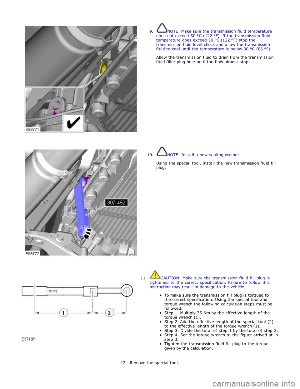
9.
10. NOTE: Make sure the transmission fluid temperature
does not exceed 50 °C (122 °F). If the transmission fluid
temperature does exceed 50 °C (122 °F) stop the
transmission fluid level check and allow the transmission
fluid to cool until the temperature is below 30 °C (86 °F).
Allow the transmission fluid to drain from the transmission
fluid filler plug hole until the flow almost stops.
NOTE: Install a new sealing washer.
Using the special tool, install the new transmission fluid fill
plug.
11. CAUTION: Make sure the transmission fluid fill plug is
tightened to the correct specification. Failure to follow this
instruction may result in damage to the vehicle.
To make sure the transmission fill plug is torqued to
the correct specification. Using the special tool and
torque wrench the following calculation steps must be
followed.
Step 1. Multiply 35 Nm by the effective length of the
torque wrench (1).
Step 2. Add the effective length of the special tool (2)
to the effective length of the torque wrench (1).
Step 3. Divide the total of step 1 by the total of step 2.
Step 4. Set the torque wrench to the figure arrived at in
step 3.
Tighten the transmission fluid fill plug to the torque
given by the calculation.
12. Remove the special tool.