2010 JAGUAR XFR length
[x] Cancel search: lengthPage 1455 of 3039
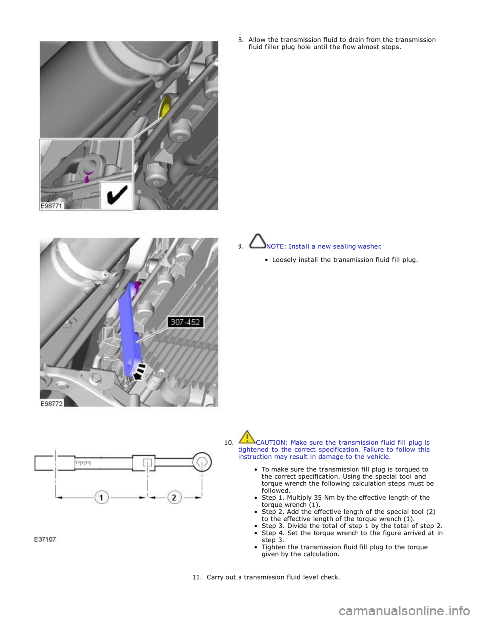
8. Allow the transmission fluid to drain from the transmission
fluid filler plug hole until the flow almost stops.
9. NOTE: Install a new sealing washer.
Loosely install the transmission fluid fill plug.
10. CAUTION: Make sure the transmission fluid fill plug is
tightened to the correct specification. Failure to follow this
instruction may result in damage to the vehicle.
To make sure the transmission fill plug is torqued to
the correct specification. Using the special tool and
torque wrench the following calculation steps must be
followed.
Step 1. Multiply 35 Nm by the effective length of the
torque wrench (1).
Step 2. Add the effective length of the special tool (2)
to the effective length of the torque wrench (1).
Step 3. Divide the total of step 1 by the total of step 2.
Step 4. Set the torque wrench to the figure arrived at in
step 3.
Tighten the transmission fluid fill plug to the torque
given by the calculation.
11. Carry out a transmission fluid level check.
Page 1642 of 3039
longitudinal axis of the vehicle. The radar operates at millimetric wavelengths (76 - 77 GHz) and transmits a frequency
modulated continuous wave signal at a relatively low power level (no high power pulses).
With the ignition ON, the adaptive speed control module is powered up but no radar transmissions are emitted until the
vehicle is in motion.
In follow mode a set speed is selected in the normal speed control manner and this speed is maintained until a slower vehicle
is encountered in the lane ahead. When the vehicle ahead comes within the effective range of the radar sensor, the system
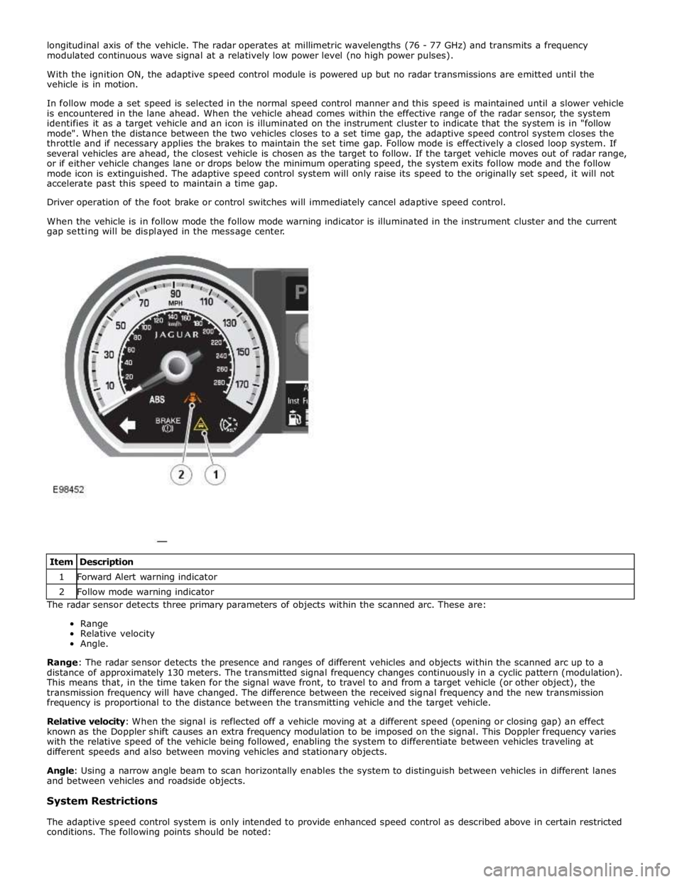
identifies it as a target vehicle and an icon is illuminated on the instrument cluster to indicate that the system is in "follow
mode". When the distance between the two vehicles closes to a set time gap, the adaptive speed control system closes the
throttle and if necessary applies the brakes to maintain the set time gap. Follow mode is effectively a closed loop system. If
several vehicles are ahead, the closest vehicle is chosen as the target to follow. If the target vehicle moves out of radar range,
or if either vehicle changes lane or drops below the minimum operating speed, the system exits follow mode and the follow
mode icon is extinguished. The adaptive speed control system will only raise its speed to the originally set speed, it will not
accelerate past this speed to maintain a time gap.
Driver operation of the foot brake or control switches will immediately cancel adaptive speed control.
When the vehicle is in follow mode the follow mode warning indicator is illuminated in the instrument cluster and the current
gap setting will be displayed in the message center.
The radar sensor detects three primary parameters of objects within the scanned arc. These are:
Range
Relative velocity
Angle.
Range: The radar sensor detects the presence and ranges of different vehicles and objects within the scanned arc up to a
distance of approximately 130 meters. The transmitted signal frequency changes continuously in a cyclic pattern (modulation).
This means that, in the time taken for the signal wave front, to travel to and from a target vehicle (or other object), the
transmission frequency will have changed. The difference between the received signal frequency and the new transmission
frequency is proportional to the distance between the transmitting vehicle and the target vehicle.
Relative velocity: When the signal is reflected off a vehicle moving at a different speed (opening or closing gap) an effect
known as the Doppler shift causes an extra frequency modulation to be imposed on the signal. This Doppler frequency varies
with the relative speed of the vehicle being followed, enabling the system to differentiate between vehicles traveling at
different speeds and also between moving vehicles and stationary objects.
Angle: Using a narrow angle beam to scan horizontally enables the system to distinguish between vehicles in different lanes
and between vehicles and roadside objects.
System Restrictions
The adaptive speed control system is only intended to provide enhanced speed control as described above in certain restricted
conditions. The following points should be noted: Item Description 1 Forward Alert warning indicator 2 Follow mode warning indicator
Page 1866 of 3039
Published: 07-Aug-2014
Battery and Charging System - General Information - Battery Care
Requirements
Description and Operation
1. INTRODUCTION
This document defines the requirements for care and maintenance of batteries, and the standard of battery care at dealers and
retailers for new vehicles.
This applies to all types of 12 Volt Lead Acid Batteries used in Jaguar and Land Rover vehicles whether they are conventional
flooded technology or Absorbed Glass Mat (AGM – also known as Valve Regulated Lead Acid (VRLA)) technology and also
applies to both Primary, Secondary and Auxiliary Batteries. AGM batteries offer improved resistance to cycling as seen in stop
start applications.
In order to prevent damage to the battery and ensure a satisfactory service life, all processes detailed within this document
must be rigorously adhered to.
It is equally important therefore to note the following key points:
All new vehicles leave the factory with either a transit relay installed and/or have a transit mode programmed into the
vehicle control modules. The transit relay must be removed and the transit mode disabled (where applicable) using an
approved diagnostic system, NOT MORE THAN 72 HOURS before the customer takes delivery.
The battery can be discharged by the following mechanisms:
- Self Discharge: - A lead acid battery will very slowly discharge itself due to its own internal chemical processes
whether it is connected to a vehicle or not.
- Quiescent Discharge: - The vehicle electrical systems when connected to the battery will draw charge from the
battery.
12 Volt Lead Acid Batteries rely on internal chemical processes to create a voltage and deliver current. These processes and
the internal chemical structure of the battery can be damaged if the battery is allowed to discharge over a number of weeks /
months, or is left in a discharged state for a lengthy time period.
On vehicles with conventional ignition keys, these must not be left in the ignition lock barrel when the transit relay
has been removed, otherwise quiescent current will increase and the battery will discharge more rapidly.
For keyless vehicles, the Smart Key must be stored at least 5m (16 ft) away from the vehicle when the vehicle is
parked or stored.
AGM Batteries are fully sealed and cannot have the electrolyte level topped up.
NOTE: Dealers and retailers involved in the storage / handling of vehicles and replacement batteries have a responsibility
to ensure that only a fully charged battery may be processed through the distribution selling chain.
2. GENERAL RULES FOR BATTERY CARE
2.1 Dealer Demonstration Vehicles
Vehicles used as dealer demonstrator(s), in a showroom, must be connected to a JLR approved showroom conditioner capable
of delivering 50 Amps. This will prevent the battery from being damaged.
2.2 Software Reflash, SDD work or Ignition On related workshop activities
Due to the high electrical current demand and high depth of discharge that can occur during vehicle software re-flash activities,
SDD work or ignition on (power mode 6) related work in the workshop, vehicles that are undergoing such activities MUST have a
JLR approved power supply capable of delivering 50 Amps or more.
2.3 Extended Vehicle Rework
For any extended vehicle rework that results in consuming vehicle power, either the battery should be disconnected or a JLR
approved power supply connected.
2.4 Jump Starting New vehicles before they have been delivered to the customer
It is the dealer / retailers responsibility to make sure the battery is not allowed to discharge by following the
instructions and processes defined in this manual.
However, if circumstances dictate that a new vehicle must be jump started due to a discharged battery whilst the
vehicle is in the dealer / retailers care, the battery on this vehicle must be replaced with a new one prior to delivery
to the customer at the dealer / retailers liability.
The vehicle should also undergo investigation as to why the battery became discharged.
Do not connect the jump starting cable to the negative (-) terminal of the battery. Always connect to the recommended
earth point. As defined in the owners handbook or service documentation for that vehicle. 2.5 AGM Batteries
AGM batteries must not be charged above 14.8 Volts. Doing so will damage them.
AGM Batteries must be tested with a capable battery tester as detailed in the Equipment section (Section 5) of this
Page 1873 of 3039

Published: 02-Apr-2014
Battery and Charging System - General Information - Battery Report Form – In Service Batteries Only
Description and Operation
NOTE: Fields marked with * are mandatory and must be completed.
General Information *Vehicle Identification Number (VIN):
Vehicle
Model: Engine type: *Mileage:
*Repair
Date: - Customer Questions *1: What is the customer’s reason for dealer visit? (tick symptoms as appropriate) Non crank
Crank but non
start Warning message Other: *2: How long was the vehicle left prior to issue. * *3: How was the car left (Locked/unlocked) * *4: How did you access to the vehicle Key fob Manual key Handle pull *5: Has the vehicle required assistance for battery issues previously? Yes No *6: Is the vehicle used? (tick symptoms as appropriate) Daily
Every other day Weekly
Less than weekly *7: Average journey length * *8: How many starts do you typically do in a day * *9: Did the customer see any instrument pack warnings prior to the
issue? * *10: Have any of the features been used
without the engine running in the last 3 days (if fitted?) Radio
Power point
accessory CD DVD USB or IPOD
connection TV
Rear seat
entertainment 11: Customer comments:- Please add any additional comments that
are relevant. * Diagnostics (Battery Testing) - - - - 1: Loose battery clamps Yes * No * 2: Loose hold down clamps Yes * No * 3: Corroded terminal posts Yes * No * 4: Physical damage/leaks Yes No * 5: Low electrolyte (Flooded batteries only) Yes * No * 6: Battery Date Code * 7: FEAD belt tension OK * Not OK * 8: Quiescent Drain mA * 9: Vent tube correctly installed Yes * No * 10: Number of Times Battery Charged: * 10: Vent tube correctly installed Yes No 11: Remove the Surface (414-00 battery care requirements) Yes * No * 12: Battery voltage * 13: Midtronics test code before charging (EXP-1080) * 13a: If Midtronics indicates that the battery needs re-charging, charge
the battery following instructions on the recommended battery charger * 13b: Midtronics test code after charge * 13c: Midtronics test code result after charge * 13d: If "good and re-charge" charge the battery following instructions
on the recommended battery charger * 13e: If "charge and re-test" for both before and after the charge
renew the battery * 13f: Only renew the battery if "renew battery", "bad cell" or charge
and re-test has been displayed twice. * Technician Comments:- Please add any additional comments that are relevant. * * * * *
Page 2032 of 3039
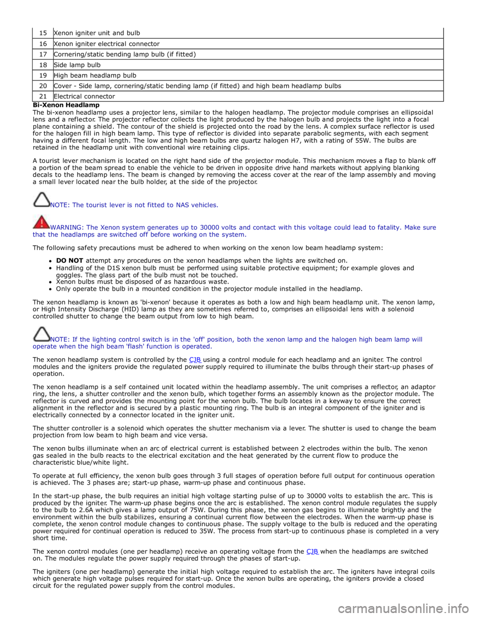
15 Xenon igniter unit and bulb 16 Xenon igniter electrical connector 17 Cornering/static bending lamp bulb (if fitted) 18 Side lamp bulb 19 High beam headlamp bulb 20 Cover - Side lamp, cornering/static bending lamp (if fitted) and high beam headlamp bulbs 21 Electrical connector Bi-Xenon Headlamp
The bi-xenon headlamp uses a projector lens, similar to the halogen headlamp. The projector module comprises an ellipsoidal
lens and a reflector. The projector reflector collects the light produced by the halogen bulb and projects the light into a focal
plane containing a shield. The contour of the shield is projected onto the road by the lens. A complex surface reflector is used
for the halogen fill in high beam lamp. This type of reflector is divided into separate parabolic segments, with each segment
having a different focal length. The low and high beam bulbs are quartz halogen H7, with a rating of 55W. The bulbs are
retained in the headlamp unit with conventional wire retaining clips.
A tourist lever mechanism is located on the right hand side of the projector module. This mechanism moves a flap to blank off
a portion of the beam spread to enable the vehicle to be driven in opposite drive hand markets without applying blanking
decals to the headlamp lens. The beam is changed by removing the access cover at the rear of the lamp assembly and moving
a small lever located near the bulb holder, at the side of the projector.
NOTE: The tourist lever is not fitted to NAS vehicles.
WARNING: The Xenon system generates up to 30000 volts and contact with this voltage could lead to fatality. Make sure
that the headlamps are switched off before working on the system.
The following safety precautions must be adhered to when working on the xenon low beam headlamp system:
DO NOT attempt any procedures on the xenon headlamps when the lights are switched on.
Handling of the D1S xenon bulb must be performed using suitable protective equipment; for example gloves and
goggles. The glass part of the bulb must not be touched.
Xenon bulbs must be disposed of as hazardous waste.
Only operate the bulb in a mounted condition in the projector module installed in the headlamp.
The xenon headlamp is known as 'bi-xenon' because it operates as both a low and high beam headlamp unit. The xenon lamp,
or High Intensity Discharge (HID) lamp as they are sometimes referred to, comprises an ellipsoidal lens with a solenoid
controlled shutter to change the beam output from low to high beam.
NOTE: If the lighting control switch is in the 'off' position, both the xenon lamp and the halogen high beam lamp will
operate when the high beam 'flash' function is operated.
The xenon headlamp system is controlled by the CJB using a control module for each headlamp and an igniter. The control modules and the igniters provide the regulated power supply required to illuminate the bulbs through their start-up phases of
operation.
The xenon headlamp is a self contained unit located within the headlamp assembly. The unit comprises a reflector, an adaptor
ring, the lens, a shutter controller and the xenon bulb, which together forms an assembly known as the projector module. The
reflector is curved and provides the mounting point for the xenon bulb. The bulb locates in a keyway to ensure the correct
alignment in the reflector and is secured by a plastic mounting ring. The bulb is an integral component of the igniter and is
electrically connected by a connector located in the igniter unit.
The shutter controller is a solenoid which operates the shutter mechanism via a lever. The shutter is used to change the beam
projection from low beam to high beam and vice versa.
The xenon bulbs illuminate when an arc of electrical current is established between 2 electrodes within the bulb. The xenon
gas sealed in the bulb reacts to the electrical excitation and the heat generated by the current flow to produce the
characteristic blue/white light.
To operate at full efficiency, the xenon bulb goes through 3 full stages of operation before full output for continuous operation
is achieved. The 3 phases are; start-up phase, warm-up phase and continuous phase.
In the start-up phase, the bulb requires an initial high voltage starting pulse of up to 30000 volts to establish the arc. This is
produced by the igniter. The warm-up phase begins once the arc is established. The xenon control module regulates the supply
to the bulb to 2.6A which gives a lamp output of 75W. During this phase, the xenon gas begins to illuminate brightly and the
environment within the bulb stabilizes, ensuring a continual current flow between the electrodes. When the warm-up phase is
complete, the xenon control module changes to continuous phase. The supply voltage to the bulb is reduced and the operating
power required for continual operation is reduced to 35W. The process from start-up to continuous phase is completed in a very
short time.
The xenon control modules (one per headlamp) receive an operating voltage from the CJB when the headlamps are switched on. The modules regulate the power supply required through the phases of start-up.
The igniters (one per headlamp) generate the initial high voltage required to establish the arc. The igniters have integral coils
which generate high voltage pulses required for start-up. Once the xenon bulbs are operating, the igniters provide a closed
circuit for the regulated power supply from the control modules.
Page 2033 of 3039
Halogen Low/high Beam Headlamp
The halogen low/high beam headlamp uses a projector lens, similar to the xenon headlamp. The projector module comprises
an ellipsoidal lens and a reflector. The projector reflector collects the light produced by the halogen bulb and projects the light
into a focal plane containing a shield. The contour of the shield is projected onto the road by the lens. The low/high beam
bulbs are quartz halogen and are retained in the headlamp unit with conventional wire retaining clips.
A tourist lever mechanism is located on the right hand side of the projector module. This mechanism moves a flap to blank off
a portion of the beam spread to enable the vehicle to be driven in opposite drive hand markets without applying blanking
decals to the headlamp lens. The beam is changed by removing the access cover at the rear of the lamp assembly and moving
a small lever located near the bulb holder, at the side of the projector.
Halogen High Beam Headlamp - Xenon and Halogen
The xenon and halogen headlamps use a complex surface reflector for the halogen fill in high beam lamp only lighting unit,
which is of the same design on both headlamp types. This type of reflector has the reflector divided into separate parabolic
segments, with each segment having a different focal length.
The high beam headlamp bulbs are quartz halogen and are retained in the headlamp unit with conventional wire retaining
clips.
Cornering Lamps
NOTE: The cornering lamps are not fitted to NAS vehicles.
The cornering lamps are an optional feature designed to illuminate the direction of travel when cornering at low speeds. The
design of the lens projects a spread of light from the vehicle at approximately 45 degrees to the vehicle axis. The cornering
lamp is incorporated into the headlamp assembly and shares the same housing as the low beam headlamp. The cornering lamp
uses a 35W Halogen H8 bulb which is permanently located in an integral holder which is connected on the headlamp housing.
The holder is located in an aperture in the headlamp housing and rotated to lock. The bulb is accessible via a removable cover
on the base of the headlamp housing.
The cornering lamps are controlled by the LH steering column multifunction switch with the lighting control switch in the headlamp position and the ignition in power mode 6. The cornering lamps are supplied power via the ignition circuit to ensure
that they do not function with the headlamp delay feature. The cornering lamps are deactivated if the vehicle speed exceeds
25 mph (40 km/h). Only one cornering lamp will illuminate at any one time. If the left hand turn signal indicators are selected
on, the left hand cornering lamp will be illuminated and vice versa, providing the vehicle speed and lighting control switch
positions are correct.
Static Bending Lamps
NOTE: The static bending lamps are not fitted to NAS vehicles.
The static bending lamps are designed to illuminate the direction of travel when cornering at low speeds. The static bending
lamp functionality, which is controlled by the CJB and the headlamp leveling module, operates using inputs from the steering angle sensor and vehicle speed information from the ABS (anti-lock brake system) module. The static bending lamp is
incorporated into the headlamp assembly and shares the same housing as the low beam headlamp. The design of the lens
projects a spread of light from the vehicle at approximately 45 degrees to the vehicle axis. The static bending lamp uses a
35W Halogen H8 bulb which locates in a holder which is connected via wires to the main connector on the headlamp housing.
The holder is located in an aperture in the headlamp housing and rotated to lock. The bulb is accessible via a removable cover
at the rear of the headlamp housing.
The static bending lamps operate with a steering angle sensor CAN bus signal which is received by the CJB. The CJB monitors this signal and vehicle speed and activates the static bending lamp bulb. When the operation parameters of the lamp are
reached, the CJB fades the static bending lamp bulb on using a PWM (pulse width modulation) voltage over a period of approximately 2 seconds. When the lamp is switched off, the CJB fades the bulb off by decreasing the PWM voltage in a linear manner depending on steering angle and vehicle speed. The cornering lamps can only be active for a maximum of 3 minutes.
NOTE: Static bending lamps only operate when the transmission is in DRIVE or in SPORT.
Turn Signal Indicators
The turn signal indicator lamp is incorporated into the outer part of the headlamp assembly. The turn signal indicator lamp
uses a PY21W bayonet orange colored bulb in ROW markets, a S8W 27/7W wedge bulb is used in NAS markets. The bulb is
fitted into a holder which connects with contacts in the headlamp housing. The holder is fitted into an aperture in the
headlamp housing and rotated to lock into position.
When active, the turn signal indicator lamps will flash at a frequency cycle of 380ms on and 380ms off. If a bulb fails, the
remaining turn signal lamps bulbs continue to flash at normal speed. The turn signal indicators in the instrument cluster will
flash at double speed to indicate the bulb failure to the driver.
Side Lamps
The side lamp is located between the headlamp projector module and the high bean headlamp. The side lamp uses a W5W
wedge fitting bulb which locates in a holder which connected via wires to the main connector on the headlamp housing. The
holder is a push fit into a receptacle in the headlamp housing. The bulb is accessible by removal of the inner cover on the rear
of the headlamp housing. Access to the bulb requires removal of the headlamp from the vehicle. The side lamps are operated
by selecting side lamps or headlamps on the lighting control switch. The side lamps are functional at all times and are
Page 2106 of 3039

essential for prevention of moisture ingress that a sealed pre-terminated wiring harness must be used where a sealed terminal
was removed.
CAUTION: Where the repair procedure indicates that a glue lined heat shrink sleeve should be applied, apply sufficient
heat to the glue lined heat shrink to melt the glue in order to provide a water tight seal. Do not over heat the glue lined heat
shrink sleeve so that the wiring harness insulation becomes damaged.
Two sizes of heat shrink sleeving are available. Each heat shrink sleeve contains a sealant glue. These must be used when
connecting wiring harness(s) or electrical connector terminal(s) at all times. The smaller diameter heat shrink sleeve is to be
used with the red and blue butt splice connectors and the larger diameter sleeve with the yellow butt splice connectors.
For ease and speed, some of the pre-terminated wiring harness(s) may already have the insulation partly stripped at the splice
end. If the repair requires insulation to be stripped from the cable, refer to the Relationship Table for the correct length of
insulation to be stripped.
The Pre-Terminated Wiring Harness(s) illustration shows the electrical connector terminal type, the part number of the
pre-terminated wiring harness and the letter of the extractor tip which must be used to extract the electrical connector
terminal from the connector housing. Additionally, those electrical connector terminal(s) which are gold are identified, all
others are therefore, tinned and not gold.
Wiring Harness Cable Identification Sleeves
A selection of colored sleeves are available for maintaining the wiring harness cable identification on the pre-terminated wiring
harness. Place the correct colored sleeve(s) over the pre-terminated wiring harness insulation as near to the electrical
connector as possible with the main wiring harness cable color nearest to the electrical connector.
For example, if the original wiring harness cable color is pink with a black trace put the pink wiring harness cable identification
sleeve on the pre-terminated wiring harness first followed by a black sleeve, and slide both along the wiring harness cable to
the electrical connector terminal.
List of Parts
Description Part Number Quantity Pre-Terminated Wiring Harness(s) 418-066 to 418-103
inclusive 10 each Glue Lined Heat Shrink Pack – small diameter 418-104 25 per pack Glue Lined Heat Shrink Pack – larger diameter 418-105 10 per pack Case Assembly Comprising – carry case, lid, inner lid, base, insert, trays foam spacers 418-106 1 Butt Splice Connector – Red 418-107 50 per pack Butt Splice Connector – Blue 418-108 50 per pack Butt Splice Connector – Yellow 418-109 20 per pack Sleeve Identification Pack – for Red insulation 418-112 500 Sleeve Identification Pack – for Blue insulation 418-113 500 Sleeve Identification Pack – for Yellow insulation 418-114 500 Harness repair components can be ordered from Jaguar/Land Rover authorised parts.
Repair Tools
The wiring harness repair tools comprises:
Crimping pliers
A wire cutter and insulation stripper
An electrical connector terminal extraction handle and tips
Extraction Handle and Tips
The extraction handle, in conjunction with the correct tip, is used to remove a terminal from an electrical connector. Each tip is
marked with an identification letter, A to K inclusive. Each tip has been specially designed to extract a particular type of
electrical connector terminal. The use of any other tool is not recommended and is liable to cause damage to the electrical
connector. The tip is fastened to the handle by a screw which holds the tip firmly yet allows it to be easily replaced.
Page 2110 of 3039
Repair Methods
CAUTION: Several different types and sizes of terminal may be found in a single electrical connector housing.
It is necessary to identify:
The conductor (wire) size of the affected wiring harness
The electrical connector range from which the damaged wiring harness is to be removed
The terminal type
Use of the approved diagnostic tool will greatly assist in the quick identification of electrical connectors and faulty pin
terminal(s).
Reference can also be made to the vehicle Electrical Guides, held by Dealers, to identify wiring harness(s) and electrical
connector(s).
By using the Relationship Table, the wiring harness conductor (wire) size can be related to a suitable pre-terminated wiring
harness by the color of the insulation. Also, the correct length of insulation to be stripped from the wiring harness lead is
identified.
Relationship Table
CABLE RANGE SPLICE STRIP LENGTH 0.35 mm² to 1.50 mm² RED 6.00 to 7.00 mm 1.00 mm² to 2.50 mm² BLUE 6.00 to 7.00 mm 4.00 mm² to 6.00 mm² YELLOW 9.00 to 9.50 mm Electrical Connector Terminal Extraction
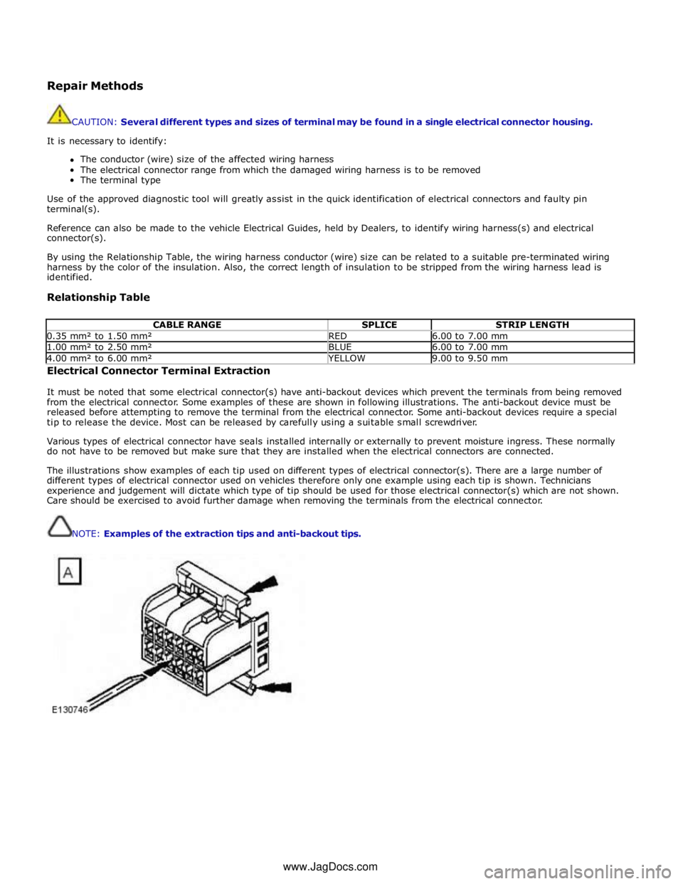
It must be noted that some electrical connector(s) have anti-backout devices which prevent the terminals from being removed
from the electrical connector. Some examples of these are shown in following illustrations. The anti-backout device must be
released before attempting to remove the terminal from the electrical connector. Some anti-backout devices require a special
tip to release the device. Most can be released by carefully using a suitable small screwdriver.
Various types of electrical connector have seals installed internally or externally to prevent moisture ingress. These normally
do not have to be removed but make sure that they are installed when the electrical connectors are connected.
The illustrations show examples of each tip used on different types of electrical connector(s). There are a large number of
different types of electrical connector used on vehicles therefore only one example using each tip is shown. Technicians
experience and judgement will dictate which type of tip should be used for those electrical connector(s) which are not shown.
Care should be exercised to avoid further damage when removing the terminals from the electrical connector.
NOTE: Examples of the extraction tips and anti-backout tips.
www.JagDocs.com