2010 JAGUAR XFR length
[x] Cancel search: lengthPage 2115 of 3039

length.
4.
5.
6.
7.
8.
9.
10.
11.
12.
13.
14.
15. NOTE: See illustration: Stripping Insulation
From the Relationship Table, find the correct length of insulation to be stripped from the pre-terminated wiring harness
and set the adjustable cable length stop to the correct length. Place the pre-terminated wiring harness in the wire
stripper and remove the insulation.
Put the cable identification sleeve(s) on to the wiring harness with the main cable colour nearest to the terminal.
During this next step do not over tighten. Place the selected butt splice connector in the crimping tool, matching the
aperture and the butt connector colours. Make sure that the window indentation in the butt connector is resting over
the guide bar on the lower jaw. Partially close the grip until the butt connector is securely held in the aperture. This will
give support to the butt connector while the pre-terminated wiring harness is inserted into it.
NOTE: See illustration: Splice Correctly Located
Insert the pre-terminated wiring harness into the butt connector and make sure that the wire is against the wire stop.
Close the grip firmly, crimping the lead to the butt connector. When the handles have been completely closed the butt
connector will be freed from the tool as the handles are released. If the handles have not been completely closed then
the jaws will hold the butt connector and it cannot be removed from the tool until the crimp is fully made by closing the
handles completely.
Make sure that the harness cable has been squarely cut and the correct length of insulation removed. If more than one
splice is needed the butt connectors must be not be crimped to the wiring harness at the same distance from the
connector. The splices must be staggered to prevent a bulk of splices in the same area of the wiring harness.
It is preferable to cover the butt splice joint with heat shrink sleeve. This is desirable not essential, except where the
electrical connector is a sealed electrical connector. Use the smaller diameter sleeve for red and blue pre-terminated
wiring harness(s) and the large diameter sleeve for the yellow pre-terminated wiring harness(s). It is advisable to place
the heat shrink over the completed joint but in some instances the sleeve will not pass over the terminal. Check, and if
required, place the correct size sleeve onto the harness cable or pre-terminated wiring harness before crimping the butt
splice to the wiring harness.
Place the harness cable into the butt splice with the splice window over the guide bar. Make sure that the cable harness
wire is against the stop in the butt splice, crimp the butt splice connector to the wiring harness.
Gently pull the harness cables each side of the butt splice to make sure that a secure joint has been made.
WARNING: Do not use a naked flame in areas where fuel or oil have been spilt. Clean the area of residual oil and
fuel and wait until the fuel spill has fully evaporated.
CAUTIONS:
When using a heat source make sure that it is localised and causes no damage to surrounding materials.
Where the repair procedure indicates that a glue lined heat shrink sleeve should be applied, apply sufficient heat
to the glue lined heat shrink to melt the glue in order to provide a water tight seal. Do not over heat the glue lined
heat shrink sleeve so that the wiring harness insulation becomes damaged.
Using a suitable heat source, shrink the sleeve over the butt splice.
If further pre-terminated wiring harness(s) are to be installed to the same electrical connector, make sure that the lead
is cut at a different length to the previous joint. This makes sure that the splices will, where possible, be staggered on
the wiring harness and prevent a bulk of splices in one area.
When all of the splices have been made, fit the terminal(s) to the electrical connector, taking care that the terminals
are correctly orientated.
Install the wiring harness cover and secure with adhesive electrical tape. Do not cover the wiring harness right to the
electrical connector as the terminals must have a little movement and not be firmly bound to the electrical connector or
wiring harness. Make sure that the cable identification sleeve(s) are showing at the wiring harness electrical connector.
www.JagDocs.com
Page 2255 of 3039
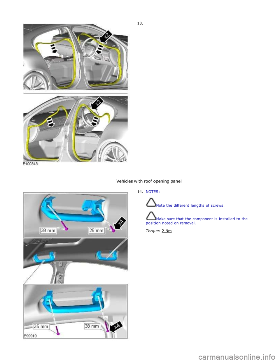
13.
Vehicles with roof opening panel
14. NOTES:
Note the different lengths of screws.
Make sure that the component is installed to the
position noted on removal.
Torque: 2 Nm
Page 2256 of 3039
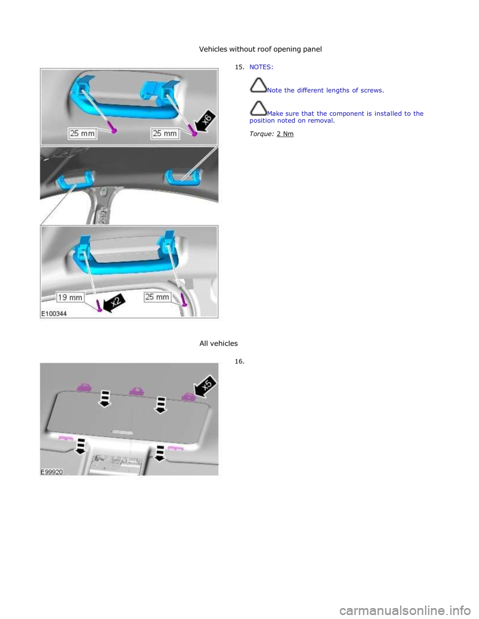
Vehicles without roof opening panel
15. NOTES:
Note the different lengths of screws.
Make sure that the component is installed to the
position noted on removal.
Torque: 2 Nm
All vehicles
16.
Page 2295 of 3039

On vehicles installed with a driver's power operated memory seat and memory exterior mirrors, a potentiometer is incorporated
within each mirror motor and is used to provide information regarding the actual motor positions. The current position and
memory positions of each door mirror motor are maintained and stored within the corresponding door control module.
The memory exterior mirror positions are also monitored and stored within door control module memory when the reverse gear
mirror dip function is used.
When reverse gear is selected, the door control module stores the current mirror positions and will then dip the passenger
mirror glass to a default dip position. While reverse gear is selected it is possible to store a preferred dipped mirror position by
adjusting the driver/passenger mirror glass to the desired position via the mirror switch pack. When the desired position is
achieved using the switch, the new dip positions will be automatically stored by the door control module when reverse gear is
de-selected. Therefore when reverse gear is re-selected, the dip position recalled by the door control module will be the new
reverse gear mirror dip stored position. When reverse gear is deselected the mirror glass will automatically move to the previous
stored position prior to reverse gear selection.
If the driver selects a memory recall function using the memory seat switch pack, the driver's memory seat and exterior
memory mirrors are moved to a stored memory position.
Exterior mirrors with the power fold/auto fold feature incorporate a motor located in the hinge of each exterior mirror arm.
Operation of the power fold feature is achieved using the exterior mirror switch pack. Operation of the auto fold feature is
achieved using the remote handset.
The power fold function is active when the ignition is in power mode 6 (Ignition).
Both exterior mirrors will power fold when the mirror switch pack 'L' and 'R' switches are pressed together. Pressing the
switches again will unfold the mirrors.
When the instrument cluster is configured for the auto fold feature, the mirrors will fold in when the remote handset lock
button is pressed. The mirrors will unfold when the vehicle is unlocked using the remote handset unlock button.
NOTE: If the mirrors are folded in using the mirror switch pack (power fold) and the vehicle is then locked, subsequent
unlocking of the vehicle will not unfold the mirrors.
When the remote handset unlock button is operated, the CJB recognizes the remote handset for that vehicle and acknowledges the request. The door control modules are connected directly to the AJB (auxiliary junction box) for power supply to the
exterior mirror folding motors.
When the vehicle is locked the door control modules reverse the polarity of the mirror fold motor, power and ground
connections to operate the mirrors in the opposite direction.
Exterior mirror heating is provided with heater elements bonded to the back of the mirror glass. Power supply for the mirror
heating elements is provided by the corresponding driver or passenger door control module via the RJB. The door control modules receive a power supply from the RJB, and are both connected on the medium speed CAN bus to the ATC (automatic temperature control) module. A ground terminal from each door control module completes the circuit. The ATC module automatically controls the mirror heating function whenever the ignition is in power mode 4 (Accessory) and power mode 6
(Ignition).
Operation of the exterior mirror heaters is fully automatic and not controllable by the driver. Exterior mirror heater operation is
determined by ambient air temperature and windshield wiper status. When ambient air temperature reaches a pre-determined
level, the ATC module broadcasts an exterior mirror heating request to the door modules over the medium speed CAN bus. On receipt of this message, the door modules provide feed and ground connections to both exterior mirror heater elements.
The mirror heating is controlled in two phases, the initial heating phase and a second PWM (pulse width modulation) controlled
phase. In the first phase the heater elements in the mirrors are permanently powered for a pre-determined length of time. This
length of time varies with the ambient temperature. During the second PWM phase, the heater elements are turned on and off every 30 seconds. The amount of time the exterior mirror heaters are operational increases if the windshield wipers are
switched on. This ensures the mirrors remain mist free in damp and wet conditions, where there is an increased risk of misting.
Page 2442 of 3039
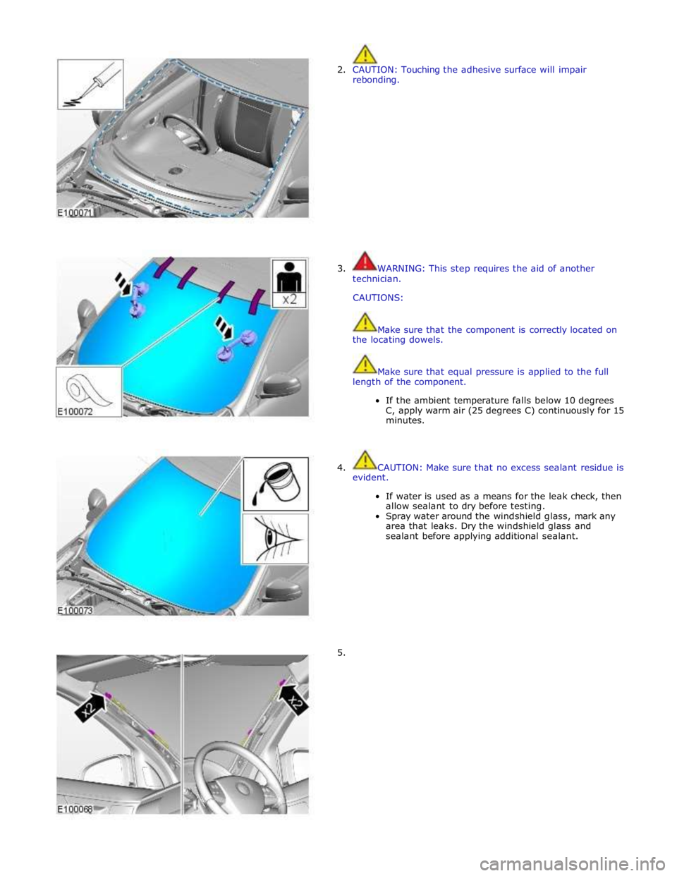
2. CAUTION: Touching the adhesive surface will impair
rebonding.
3. WARNING: This step requires the aid of another
technician.
CAUTIONS:
Make sure that the component is correctly located on
the locating dowels.
Make sure that equal pressure is applied to the full
length of the component.
If the ambient temperature falls below 10 degrees
C, apply warm air (25 degrees C) continuously for 15
minutes.
4. CAUTION: Make sure that no excess sealant residue is
evident.
If water is used as a means for the leak check, then
allow sealant to dry before testing.
Spray water around the windshield glass, mark any
area that leaks. Dry the windshield glass and
sealant before applying additional sealant.
5.
Page 2540 of 3039
and is connected at the opposite end to the LH pivot housing via a crank. The LH pivot housing crank is fitted with a second link rod which is connected directly to the crank on the RH pivot housing.
The motor crank converts rotary motion from the motor output shaft into linear movement of the link rods. The cranks
connected to each pivot housing, convert the linear motion of the link rods back to rotary motion of the pivot housings. This
rotary motion is passed to the wiper arms and blades causing the blades to wipe an arc across the windshield.
Each wiper arm is located on a taper spline on the respective pivot housing. A nut is screwed on the end of the pivot housing
shaft and positively secures the wiper arm on the taper spline.
The wiper blades are attached to the wiper arms with a quick release fittings. The blades are of the flat blade type. These
blades have an integral spring along their full length which curves the blade to match the windshield and provides even blade
to windshield contact pressure along the entire length of the blade.
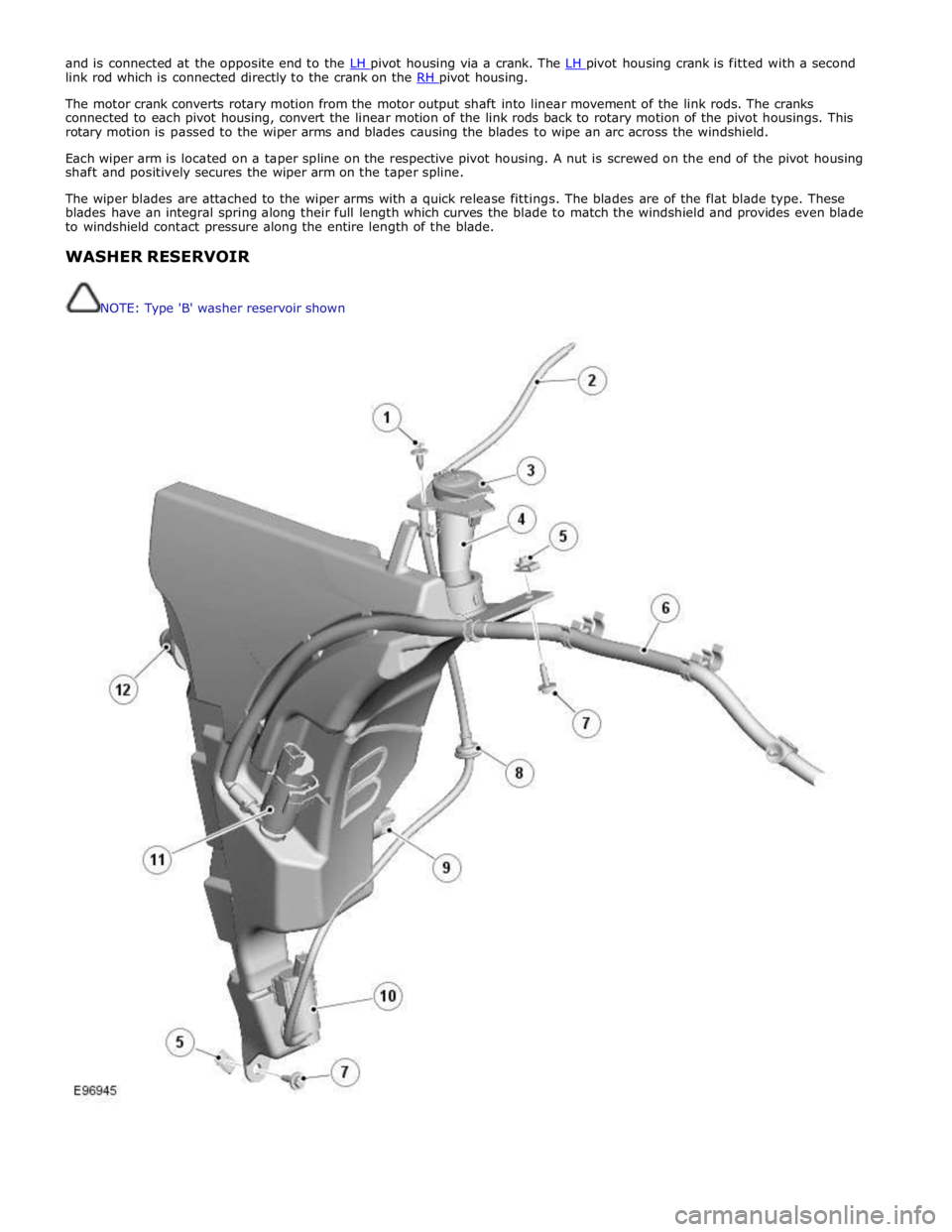
WASHER RESERVOIR
NOTE: Type 'B' washer reservoir shown
Page 2676 of 3039
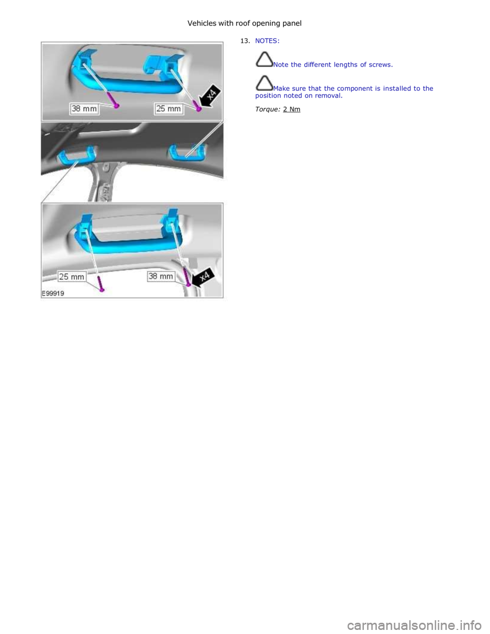
Vehicles with roof opening panel
13. NOTES:
Note the different lengths of screws.
Make sure that the component is installed to the
position noted on removal.
Torque: 2 Nm
Page 2677 of 3039
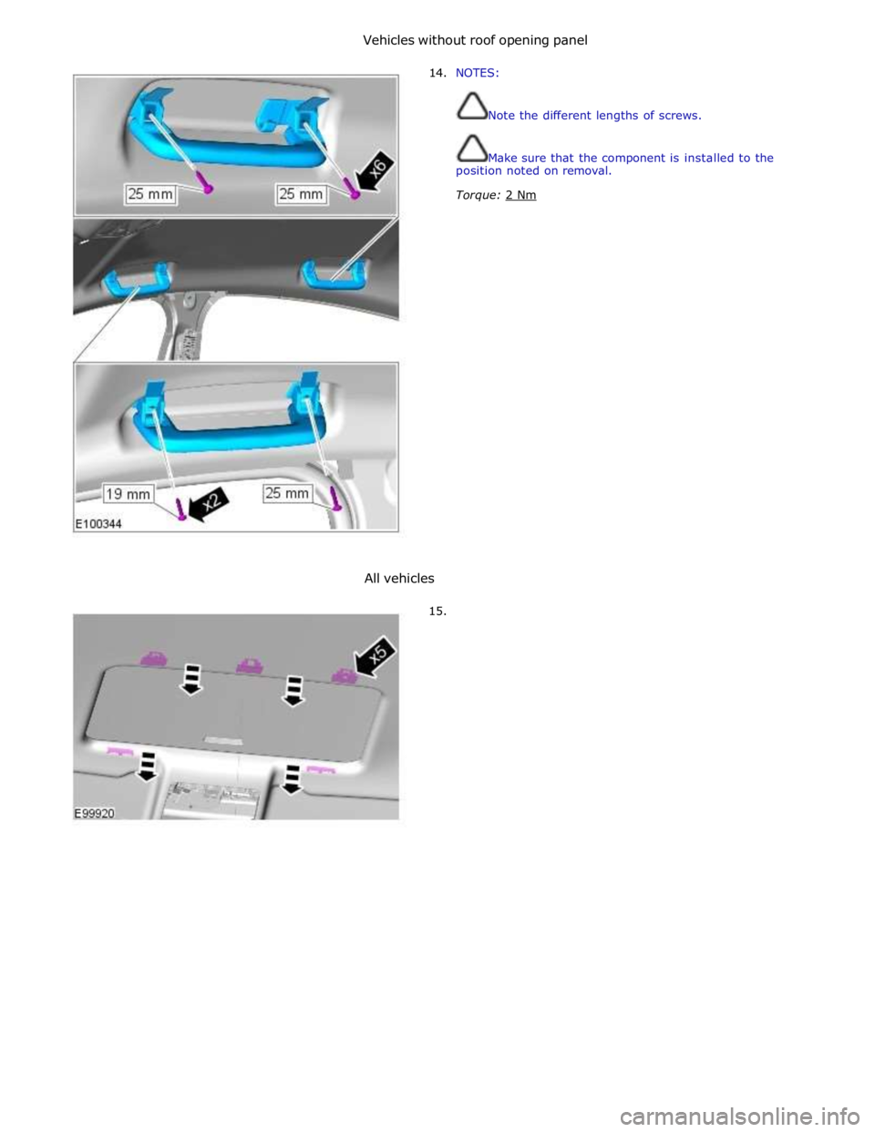
Vehicles without roof opening panel
14. NOTES:
Note the different lengths of screws.
Make sure that the component is installed to the
position noted on removal.
Torque: 2 Nm
All vehicles
15.