Page 336 of 3039

Front Suspension - Front Shock Absorber
Removal and Installation Published: 09-Oct-2012
NOTES: Removal
Fuse box release only required on removal of the RH front shock absorber.
Expansion tank release only required for supercharged variant removal of the LH front shock absorber.
All vehicles
1. WARNING: Do not work on or under a vehicle supported only by a
jack. Always support the vehicle on safety stands.
Raise and support the vehicle.
2. Remove the front wheel and tire.
For additional information, refer to: Wheel and Tire (204-04 Wheels and Tires, Removal and Installation).
3. Remove the front stabilizer bar link.
For additional information, refer to: Front Stabilizer Bar Link (204-01 Front Suspension, Removal and Installation).
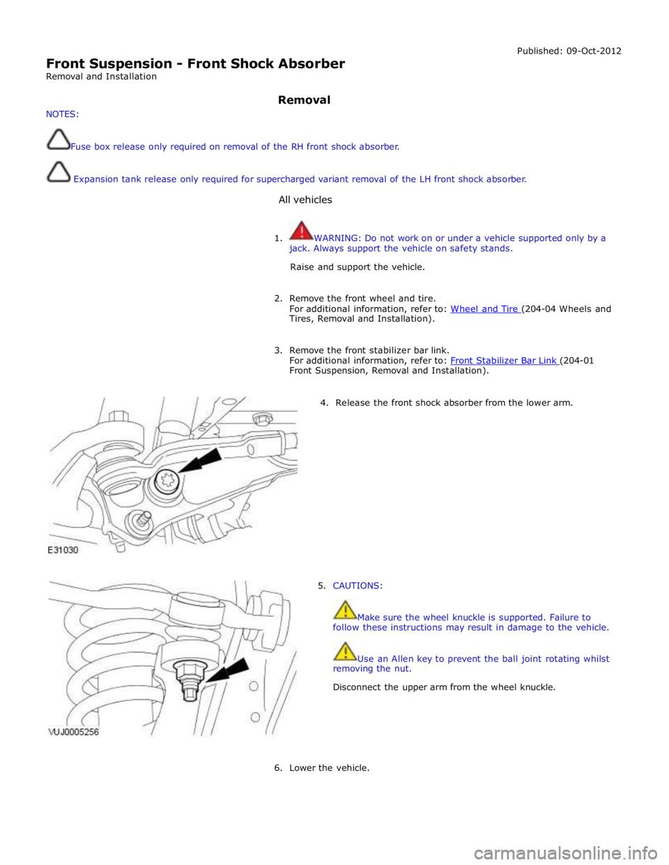
4. Release the front shock absorber from the lower arm.
5. CAUTIONS:
Make sure the wheel knuckle is supported. Failure to
follow these instructions may result in damage to the vehicle.
Use an Allen key to prevent the ball joint rotating whilst
removing the nut.
Disconnect the upper arm from the wheel knuckle.
6. Lower the vehicle.
Page 340 of 3039
4. Connect the front shock absorber electrical connector.
All vehicles
5. Secure the fuse box.
6. Secure the coolant expansion tank.
Tighten to 10 Nm.
7. Raise the vehicle.
Page 442 of 3039
Published: 11-May-2011
Wheels and Tires - Wheels and Tires - System Operation and Component Description
Description and Operation
Control Diagram
NOTE: A = Hardwired; F = RF Transmission; N = Medium speed CAN bus; W = LF Transmission
Item Description 1 Battery 2 Megafuse (250A) 3 CJB (central junction box) 4 RJB (rear junction box) 5 TPMS receiver 6 Tire pressure sensors
Page 482 of 3039
Published: 11-May-2011
Vehicle Dynamic Suspension - Vehicle Dynamic Suspension V8 5.0L Petrol/V8 S/C 5.0L Petrol - System Operation and Component Description
Description and Operation
Control Diagram
NOTE: A = Hardwired; D = High speed CAN (controller area network) bus
Item Description 1 Battery 2 BJB (battery junction box) (Megafuse (250 A) 3 AJB (auxiliary junction box) 4 CJB (central junction box) 5 ATC (automatic temperature control) module 6 Fuse 36 (10 A) - from delayed power-off relay
Page 531 of 3039
Published: 11-May-2011
Rear Drive Axle/Differential - Rear Drive Axle and Differential - System
Operation and Component Description
Description and Operation
Control Diagram
NOTE: A = Hardwired; D = High speed CAN (controller area network) bus
Control Diagram - 5.0L Supercharger Vehicles Only
Item Description 1 Battery 2 Megafuse (175 A) 3 AJB (auxiliary junction box) 4 Motor
Page 609 of 3039
Published: 11-May-2011
Front Disc Brake - TDV6 3.0L Diesel /V8 5.0L Petrol/V8 S/C 5.0L Petrol - Front Disc Brake - System Operation and Component Description
Description and Operation
Control Diagram
NOTE: A = Hardwired
Item Description 1 Battery 2 Megafuse (250 A) 3 Front brake pad wear sensor 4 Rear brake pad wear sensor 5 Instrument cluster 6 CJB (central junction box) 7 Power distribution box
Page 631 of 3039
Published: 11-May-2011
Rear Disc Brake - TDV6 3.0L Diesel /V8 5.0L Petrol/V8 S/C 5.0L Petrol - Rear
Disc Brake - System Operation and Component Description
Description and Operation
Control Diagram
NOTE: A = Hardwired
Item Description 1 Battery 2 Megafuse (250 A) 3 Front brake pad wear sensor 4 Rear brake pad wear sensor 5 Instrument cluster 6 CJB (central junction box) 7Powerdistributionbox
Page 680 of 3039
6. Release the fuse box.
7. Remove the brake master cylinder.
Installation
1. To install, reverse the removal procedure.
Install new O-ring seals. www.JagDocs.com