2010 JAGUAR XFR fuel consumption
[x] Cancel search: fuel consumptionPage 441 of 3039

provides the following benefits:
Maintain optimal fuel consumption.
Maintain ride and handling characteristics.
Reduce the risk of rapid tire deflation - which may be caused by under inflated tires.
Comply with legislation requirements in relevant markets.
CAUTION: TPMS is not intended as a replacement for regular tire pressure and tire condition checks and should be
considered as additional to good tire maintenance practices.
The TPMS measures the pressure in each of the vehicle's tires and issues warnings to the driver if any of the pressures deviate
from defined tolerances. The space saver spare wheel is not monitored.
NOTE: TPMS is not designed to warn the driver of a tire 'blow-out', as due to the short duration of a 'blow-out', it is not
possible to give the driver sufficient warning that such an event is occurring. The design of the TPMS is to assist the driver in
keeping the tires at the correct pressure, which will assist to reduce the likelihood of a tire 'blow-out' occurring.
Page 812 of 3039

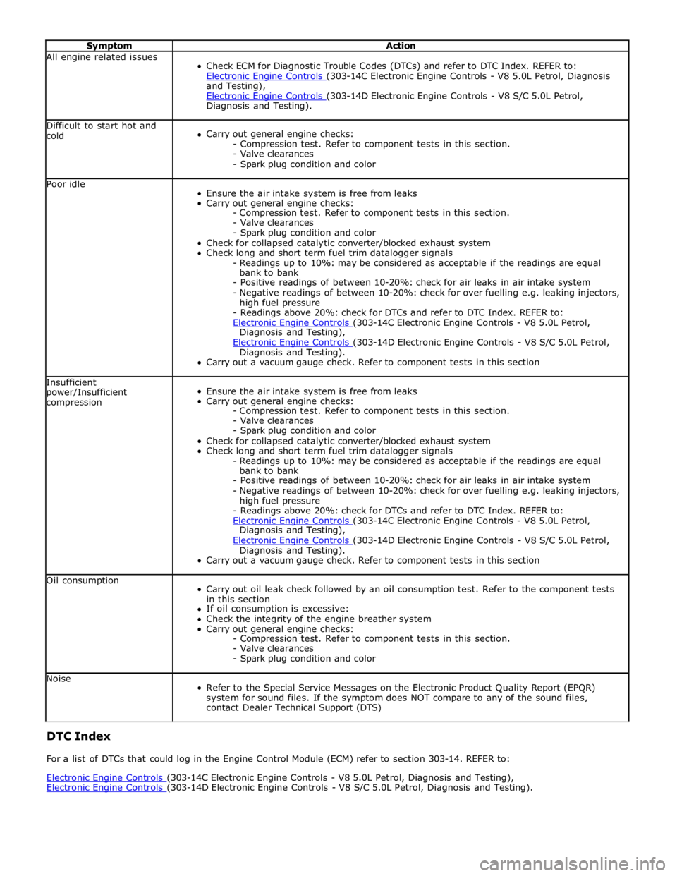
Symptom Action All engine related issues
Check ECM for Diagnostic Trouble Codes (DTCs) and refer to DTC Index. REFER to:
Electronic Engine Controls (303-14C Electronic Engine Controls - V8 5.0L Petrol, Diagnosis and Testing),
Electronic Engine Controls (303-14D Electronic Engine Controls - V8 S/C 5.0L Petrol, Diagnosis and Testing). Difficult to start hot and
cold
Carry out general engine checks:
- Compression test. Refer to component tests in this section.
- Valve clearances
- Spark plug condition and color Poor idle
Ensure the air intake system is free from leaks
Carry out general engine checks:
- Compression test. Refer to component tests in this section.
- Valve clearances
- Spark plug condition and color
Check for collapsed catalytic converter/blocked exhaust system
Check long and short term fuel trim datalogger signals
- Readings up to 10%: may be considered as acceptable if the readings are equal
bank to bank
- Positive readings of between 10-20%: check for air leaks in air intake system
- Negative readings of between 10-20%: check for over fuelling e.g. leaking injectors,
high fuel pressure
- Readings above 20%: check for DTCs and refer to DTC Index. REFER to:
Electronic Engine Controls (303-14C Electronic Engine Controls - V8 5.0L Petrol, Diagnosis and Testing),
Electronic Engine Controls (303-14D Electronic Engine Controls - V8 S/C 5.0L Petrol, Diagnosis and Testing).
Carry out a vacuum gauge check. Refer to component tests in this section Insufficient
power/Insufficient
compression
Ensure the air intake system is free from leaks
Carry out general engine checks:
- Compression test. Refer to component tests in this section.
- Valve clearances
- Spark plug condition and color
Check for collapsed catalytic converter/blocked exhaust system
Check long and short term fuel trim datalogger signals
- Readings up to 10%: may be considered as acceptable if the readings are equal
bank to bank
- Positive readings of between 10-20%: check for air leaks in air intake system
- Negative readings of between 10-20%: check for over fuelling e.g. leaking injectors,
high fuel pressure
- Readings above 20%: check for DTCs and refer to DTC Index. REFER to:
Electronic Engine Controls (303-14C Electronic Engine Controls - V8 5.0L Petrol, Diagnosis and Testing),
Electronic Engine Controls (303-14D Electronic Engine Controls - V8 S/C 5.0L Petrol, Diagnosis and Testing).
Carry out a vacuum gauge check. Refer to component tests in this section Oil consumption
Carry out oil leak check followed by an oil consumption test. Refer to the component tests
in this section
If oil consumption is excessive:
Check the integrity of the engine breather system
Carry out general engine checks:
- Compression test. Refer to component tests in this section.
- Valve clearances
- Spark plug condition and color Noise
Refer to the Special Service Messages on the Electronic Product Quality Report (EPQR)
system for sound files. If the symptom does NOT compare to any of the sound files,
contact Dealer Technical Support (DTS) DTC Index
For a list of DTCs that could log in the Engine Control Module (ECM) refer to section 303-14. REFER to:
Electronic Engine Controls (303-14C Electronic Engine Controls - V8 5.0L Petrol, Diagnosis and Testing), Electronic Engine Controls (303-14D Electronic Engine Controls - V8 S/C 5.0L Petrol, Diagnosis and Testing).
Page 814 of 3039

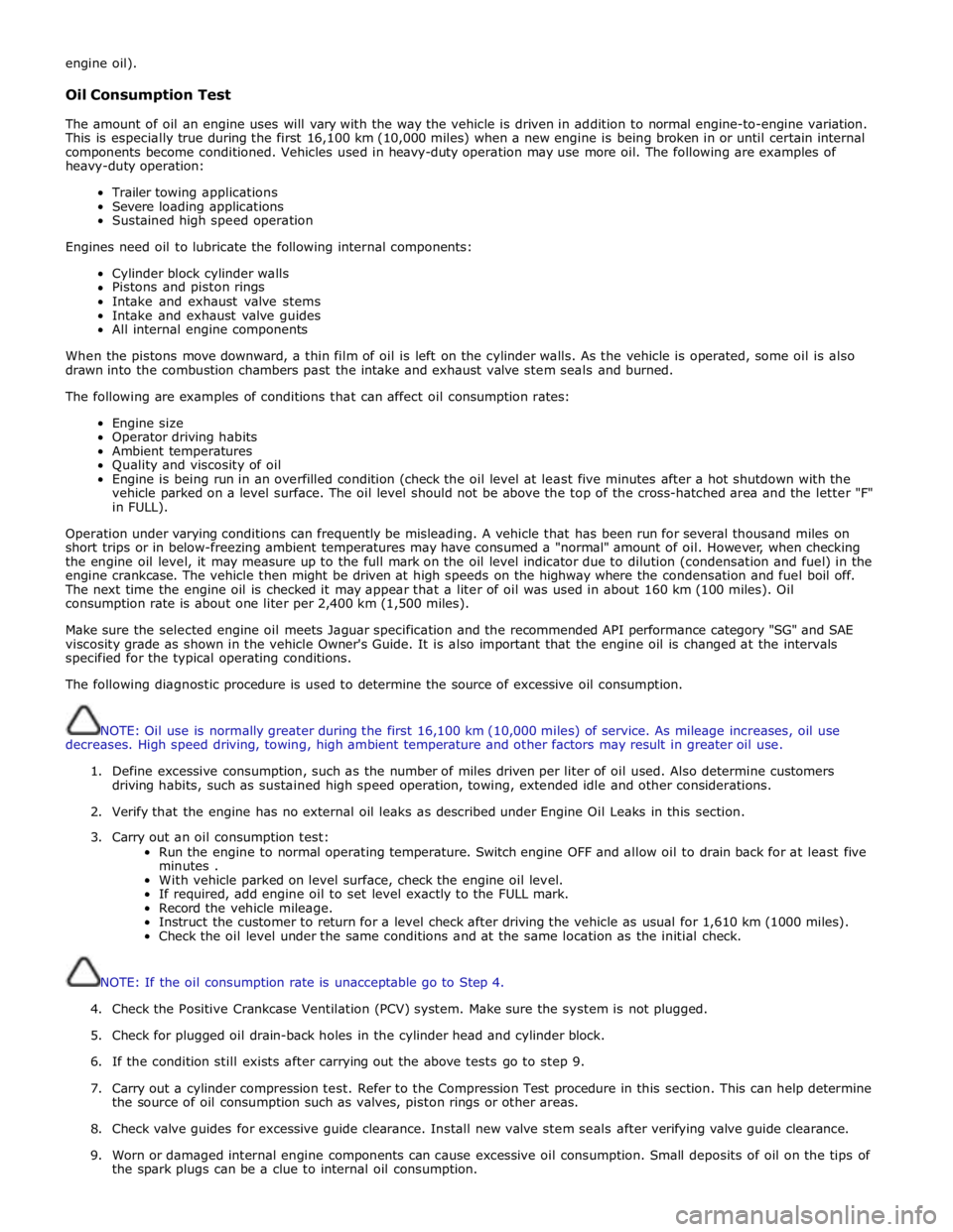
engine oil).
Oil Consumption Test
The amount of oil an engine uses will vary with the way the vehicle is driven in addition to normal engine-to-engine variation.
This is especially true during the first 16,100 km (10,000 miles) when a new engine is being broken in or until certain internal
components become conditioned. Vehicles used in heavy-duty operation may use more oil. The following are examples of
heavy-duty operation:
Trailer towing applications
Severe loading applications
Sustained high speed operation
Engines need oil to lubricate the following internal components:
Cylinder block cylinder walls
Pistons and piston rings
Intake and exhaust valve stems
Intake and exhaust valve guides
All internal engine components
When the pistons move downward, a thin film of oil is left on the cylinder walls. As the vehicle is operated, some oil is also
drawn into the combustion chambers past the intake and exhaust valve stem seals and burned.
The following are examples of conditions that can affect oil consumption rates:
Engine size
Operator driving habits
Ambient temperatures
Quality and viscosity of oil
Engine is being run in an overfilled condition (check the oil level at least five minutes after a hot shutdown with the
vehicle parked on a level surface. The oil level should not be above the top of the cross-hatched area and the letter "F"
in FULL).
Operation under varying conditions can frequently be misleading. A vehicle that has been run for several thousand miles on
short trips or in below-freezing ambient temperatures may have consumed a "normal" amount of oil. However, when checking
the engine oil level, it may measure up to the full mark on the oil level indicator due to dilution (condensation and fuel) in the
engine crankcase. The vehicle then might be driven at high speeds on the highway where the condensation and fuel boil off.
The next time the engine oil is checked it may appear that a liter of oil was used in about 160 km (100 miles). Oil
consumption rate is about one liter per 2,400 km (1,500 miles).
Make sure the selected engine oil meets Jaguar specification and the recommended API performance category "SG" and SAE
viscosity grade as shown in the vehicle Owner's Guide. It is also important that the engine oil is changed at the intervals
specified for the typical operating conditions.
The following diagnostic procedure is used to determine the source of excessive oil consumption.
NOTE: Oil use is normally greater during the first 16,100 km (10,000 miles) of service. As mileage increases, oil use
decreases. High speed driving, towing, high ambient temperature and other factors may result in greater oil use.
1. Define excessive consumption, such as the number of miles driven per liter of oil used. Also determine customers
driving habits, such as sustained high speed operation, towing, extended idle and other considerations.
2. Verify that the engine has no external oil leaks as described under Engine Oil Leaks in this section.
3. Carry out an oil consumption test:
Run the engine to normal operating temperature. Switch engine OFF and allow oil to drain back for at least five
minutes .
With vehicle parked on level surface, check the engine oil level.
If required, add engine oil to set level exactly to the FULL mark.
Record the vehicle mileage.
Instruct the customer to return for a level check after driving the vehicle as usual for 1,610 km (1000 miles).
Check the oil level under the same conditions and at the same location as the initial check.
NOTE: If the oil consumption rate is unacceptable go to Step 4.
4. Check the Positive Crankcase Ventilation (PCV) system. Make sure the system is not plugged.
5. Check for plugged oil drain-back holes in the cylinder head and cylinder block.
6. If the condition still exists after carrying out the above tests go to step 9.
7. Carry out a cylinder compression test. Refer to the Compression Test procedure in this section. This can help determine
the source of oil consumption such as valves, piston rings or other areas.
8. Check valve guides for excessive guide clearance. Install new valve stem seals after verifying valve guide clearance.
9. Worn or damaged internal engine components can cause excessive oil consumption. Small deposits of oil on the tips of
the spark plugs can be a clue to internal oil consumption.
Page 1429 of 3039

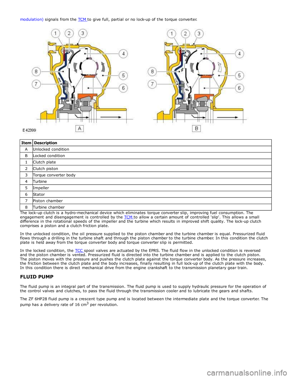
Item Description A Unlocked condition B Locked condition 1 Clutch plate 2 Clutch piston 3 Torque converter body 4 Turbine 5 Impeller 6 Stator 7 Piston chamber 8 Turbine chamber The lock-up clutch is a hydro-mechanical device which eliminates torque converter slip, improving fuel consumption. The
engagement and disengagement is controlled by the TCM to allow a certain amount of controlled 'slip'. This allows a small difference in the rotational speeds of the impeller and the turbine which results in improved shift quality. The lock-up clutch
comprises a piston and a clutch friction plate.
In the unlocked condition, the oil pressure supplied to the piston chamber and the turbine chamber is equal. Pressurized fluid
flows through a drilling in the turbine shaft and through the piston chamber to the turbine chamber. In this condition the clutch
plate is held away from the torque converter body and torque converter slip is permitted.
In the locked condition, the TCC spool valves are actuated by the EPRS. The fluid flow in the unlocked condition is reversed and the piston chamber is vented. Pressurized fluid is directed into the turbine chamber and is applied to the clutch piston.
The piston moves with the pressure and pushes the clutch plate against the torque converter body. As the pressure increases,
the friction between the clutch plate and the body increases, finally resulting in full lock-up of the clutch plate with the body.
In this condition there is direct mechanical drive from the engine crankshaft to the transmission planetary gear train.
FLUID PUMP
The fluid pump is an integral part of the transmission. The fluid pump is used to supply hydraulic pressure for the operation of
the control valves and clutches, to pass the fluid through the transmission cooler and to lubricate the gears and shafts.
The ZF 6HP28 fluid pump is a crescent type pump and is located between the intermediate plate and the torque converter. The
pump has a delivery rate of 16 cm3
per revolution.
Page 1829 of 3039

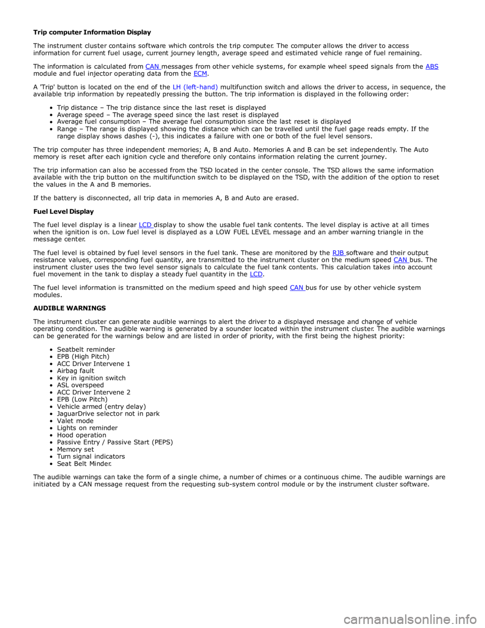
module and fuel injector operating data from the ECM.
A 'Trip' button is located on the end of the LH (left-hand) multifunction switch and allows the driver to access, in sequence, the
available trip information by repeatedly pressing the button. The trip information is displayed in the following order:
Trip distance – The trip distance since the last reset is displayed
Average speed – The average speed since the last reset is displayed
Average fuel consumption – The average fuel consumption since the last reset is displayed
Range – The range is displayed showing the distance which can be travelled until the fuel gage reads empty. If the
range display shows dashes (-), this indicates a failure with one or both of the fuel level sensors.
The trip computer has three independent memories; A, B and Auto. Memories A and B can be set independently. The Auto
memory is reset after each ignition cycle and therefore only contains information relating the current journey.
The trip information can also be accessed from the TSD located in the center console. The TSD allows the same information
available with the trip button on the multifunction switch to be displayed on the TSD, with the addition of the option to reset
the values in the A and B memories.
If the battery is disconnected, all trip data in memories A, B and Auto are erased.
Fuel Level Display
The fuel level display is a linear LCD display to show the usable fuel tank contents. The level display is active at all times when the ignition is on. Low fuel level is displayed as a LOW FUEL LEVEL message and an amber warning triangle in the
message center.
The fuel level is obtained by fuel level sensors in the fuel tank. These are monitored by the RJB software and their output resistance values, corresponding fuel quantity, are transmitted to the instrument cluster on the medium speed CAN bus. The instrument cluster uses the two level sensor signals to calculate the fuel tank contents. This calculation takes into account
fuel movement in the tank to display a steady fuel quantity in the LCD.
The fuel level information is transmitted on the medium speed and high speed CAN bus for use by other vehicle system modules.
AUDIBLE WARNINGS
The instrument cluster can generate audible warnings to alert the driver to a displayed message and change of vehicle
operating condition. The audible warning is generated by a sounder located within the instrument cluster. The audible warnings
can be generated for the warnings below and are listed in order of priority, with the first being the highest priority:
Seatbelt reminder
EPB (High Pitch)
ACC Driver Intervene 1
Airbag fault
Key in ignition switch
ASL overspeed
ACC Driver Intervene 2
EPB (Low Pitch)
Vehicle armed (entry delay)
JaguarDrive selector not in park
Valet mode
Lights on reminder
Hood operation
Passive Entry / Passive Start (PEPS)
Memory set
Turn signal indicators
Seat Belt Minder.
The audible warnings can take the form of a single chime, a number of chimes or a continuous chime. The audible warnings are
initiated by a CAN message request from the requesting sub-system control module or by the instrument cluster software.