2010 JAGUAR XFR brake
[x] Cancel search: brakePage 2 of 3039

Table of ContentsContents1: General Information
100: Service Information
100-00: General Information
Description and OperationAbout This Manual
Application and Use of Specifications
Battery and Battery Charging Health and Safety Precautions
Brake System Health and Safety Precautions
Diesel Fuel System Health and Safety Precautions
General Service Information
Health and Safety Precautions
How To Use This Manual
Important Safety Instructions
Petrol and Petrol-Ethanol Fuel Systems Health and Safety Precautions
Solvents, Sealants and Adhesives
Standard Workshop Practices
Symbols Glossary
Supplemental Restraint System (SRS) Health and Safety Precautions
Road/Roller Testing
Window Glass Health and Safety Precautions
Diagnostic Trouble Code (DTC) IndexDTC: Adaptive Damping Module (SUMB)
Diagnostic Trouble Code (DTC) IndexDTC: Anti-Lock Braking System (ABS)
Diagnostic Trouble Code (DTC) IndexDTC: Audio Amplifier Module (AAM)
Diagnostic Trouble Code (DTC) IndexDTC: Blind Spot Monitoring System Module (SODL/SODR)
Diagnostic Trouble Code (DTC) IndexDTC: Central Junction Box (CJB)
Diagnostic Trouble Code (DTC) IndexDTC: Climate Control Module (HVAC)
Diagnostic Trouble Code (DTC) IndexDTC: Digital Audio Broadcast Module (DABM)
Diagnostic Trouble Code (DTC) IndexDTC: Driver Door Module/Passenger Door Module (DDM/PDM)
Diagnostic Trouble Code (DTC) IndexDTC: Driver/Passenger Seat Module (DSM/PSM)
Diagnostic Trouble Code (DTC) IndexDTC: Electric Parking Brake (PBM)
Diagnostic Trouble Code (DTC) Index V8 S/C 5.0L Petrol, DTC: Engine Control Module (ECM)
Diagnostic Trouble Code (DTC) IndexDTC: Front Seat Climate Control Module (DCSM)
Diagnostic Trouble Code (DTC) IndexDTC: Headlamp Control Module (HCM)
Diagnostic Trouble Code (DTC) IndexDTC: Instrument Cluster (IPC)
Diagnostic Trouble Code (DTC) IndexDTC: Integrated Audio Module (IAM)
Diagnostic Trouble Code (DTC) IndexDTC: Integrated Control Panel (FCIMB)
Page 6 of 3039

Component Location
Overview
System Operation and Component Description
Component Location
Overview
System Operation and Component DescriptionDiagnosis and TestingDriveshaftGeneral ProceduresDriveshaft Runout and BalancingRemoval and InstallationDriveshaft - V8 5.0L Petrol/V8 S/C 5.0L Petrol205-02: Rear Drive Axle/DifferentialSpecification - TDV6 3.0L Diesel /V8 5.0L Petrol/V8 S/C 5.0L PetrolDescription and OperationComponent Location
Overview
System Operation and Component DescriptionDiagnosis and TestingRear Drive Axle and DifferentialGeneral ProceduresDifferential Draining and FillingRemoval and InstallationDifferential Case - TDV6 3.0L Diesel /V8 5.0L Petrol/V8 S/C 5.0L Petrol
Differential Front Bushing - TDV6 3.0L Diesel /V8 5.0L Petrol/V8 S/C 5.0L Petrol
Drive Pinion Seal
Differential Locking Motor205-05: Rear Drive HalfshaftsSpecificationDescription and OperationComponent Location
Overview
System Operation and Component DescriptionDiagnosis and TestingRear Drive HalfshaftsRemoval and InstallationRear Halfshaft - TDV6 3.0L Diesel /V8 5.0L Petrol/V8 S/C 5.0L Petrol
Inner Constant Velocity (CV) Joint Boot (47.10.33)
Outer Constant Velocity (CV) Joint Boot (47.10.32)206: Brake System
206-00: Brake System - General InformationSpecification - TDV6 3.0L Diesel /V8 5.0L Petrol/V8 S/C 5.0L PetrolDescription and Operation
Page 7 of 3039

Diagnosis and TestingBrake SystemGeneral ProceduresBrake Disc Runout Check
Brake System Bleeding (70.25.03)
Front Brake Disc Runout Check - With Wheel On - Vehicles With: High Performance Brakes
Rear Brake Disc Runout Check - With Wheel On206-03B: Front Disc Brake - TDV6 3.0L Diesel /V8 5.0L Petrol/V8 S/C 5.0L PetrolSpecificationDescription and OperationComponent Location
Overview
System Operation and Component DescriptionRemoval and InstallationBrake Caliper - Vehicles With: High Performance Brakes
Brake Disc - Vehicles With: High Performance Brakes
Brake Pads - Vehicles With: High Performance Brakes
Brake Disc Shield (70.10.18) - Vehicles With: High Performance Brakes206-04B: Rear Disc Brake - TDV6 3.0L Diesel /V8 5.0L Petrol/V8 S/C 5.0L PetrolSpecificationDescription and OperationComponent Location
Overview
System Operation and Component DescriptionRemoval and InstallationBrake Caliper - Vehicles With: High Performance Brakes
Brake Disc - Vehicles With: High Performance Brakes
Brake Pads - Vehicles With: High Performance Brakes
Brake Disc Shield (70.10.19)206-05: Parking Brake and ActuationSpecificationDescription and OperationComponent Location
Overview
System Operation and Component DescriptionDiagnosis and TestingParking BrakeGeneral ProceduresParking Brake Cable Tension ReleaseRemoval and InstallationParking Brake Cable LH - TDV6 3.0L Diesel /V8 5.0L Petrol/V8 S/C 5.0L Petrol
Parking Brake Cable RH - TDV6 3.0L Diesel /V8 5.0L Petrol/V8 S/C 5.0L Petrol
Page 8 of 3039

Parking Brake Module
Parking Brake Switch
Parking Brake Release Actuator206-06: Hydraulic Brake ActuationSpecificationDescription and OperationComponent Location
Overview
System Operation and Component DescriptionDiagnosis and TestingHydraulic Brake ActuationRemoval and InstallationBrake Fluid Reservoir (70.30.16)
Brake Master Cylinder (70.30.08)206-07: Power Brake ActuationSpecificationDescription and OperationComponent Location
OverviewDiagnosis and TestingPower Brake SystemRemoval and InstallationBrake Booster (70.50.17)
Brake Vacuum Pump - V8 5.0L Petrol/V8 S/C 5.0L Petrol206-09: Anti-Lock Control - Stability AssistSpecificationDescription and OperationComponent Location
Overview
System Operation and Component DescriptionDiagnosis and TestingAnti-Lock Control - Stability AssistRemoval and InstallationAnti-Lock Brake System (ABS) Module (70.60.02)
Front Wheel Speed Sensor
Hydraulic Control Unit (HCU) (70.60.18) (70.60.19)
Rear Wheel Speed Sensor (70.60.04)
Steering Wheel Rotation Sensor
Yaw Rate Sensor and Accelerometer211: Steering System
211-00: Steering System - General InformationSpecification
Page 46 of 3039

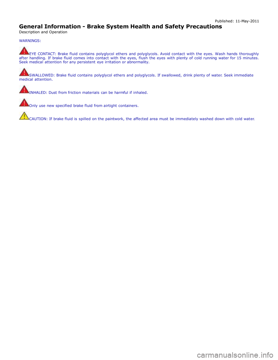
Published: 11-May-2011
General Information - Brake System Health and Safety Precautions
Description and Operation
WARNINGS:
EYE CONTACT: Brake fluid contains polyglycol ethers and polyglycols. Avoid contact with the eyes. Wash hands thoroughly
after handling. If brake fluid comes into contact with the eyes, flush the eyes with plenty of cold running water for 15 minutes.
Seek medical attention for any persistent eye irritation or abnormality.
SWALLOWED: Brake fluid contains polyglycol ethers and polyglycols. If swallowed, drink plenty of water. Seek immediate
medical attention.
INHALED: Dust from friction materials can be harmful if inhaled.
Only use new specified brake fluid from airtight containers.
CAUTION: If brake fluid is spilled on the paintwork, the affected area must be immediately washed down with cold water.
Page 51 of 3039

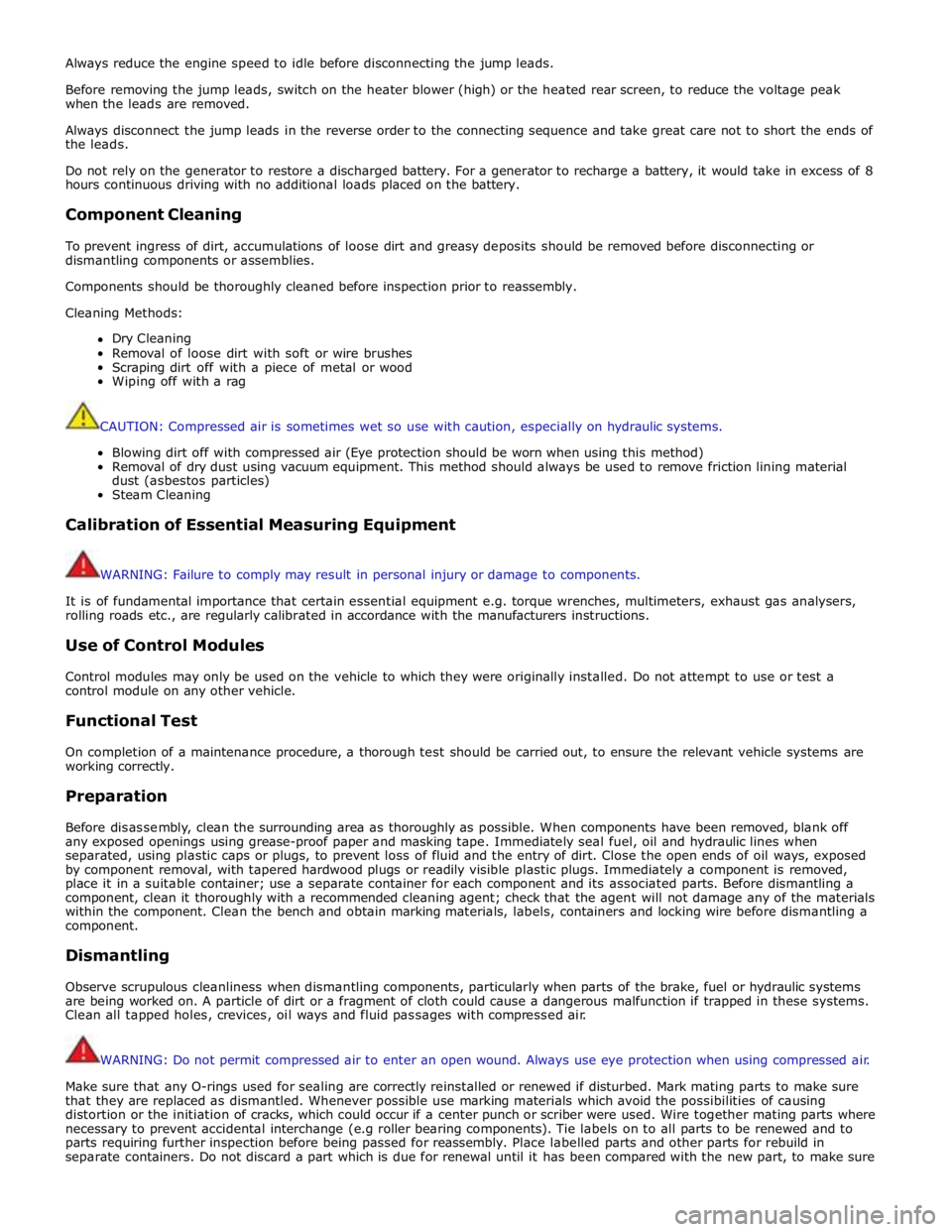
Always reduce the engine speed to idle before disconnecting the jump leads.
Before removing the jump leads, switch on the heater blower (high) or the heated rear screen, to reduce the voltage peak
when the leads are removed.
Always disconnect the jump leads in the reverse order to the connecting sequence and take great care not to short the ends of
the leads.
Do not rely on the generator to restore a discharged battery. For a generator to recharge a battery, it would take in excess of 8
hours continuous driving with no additional loads placed on the battery.
Component Cleaning
To prevent ingress of dirt, accumulations of loose dirt and greasy deposits should be removed before disconnecting or
dismantling components or assemblies.
Components should be thoroughly cleaned before inspection prior to reassembly.
Cleaning Methods:
Dry Cleaning
Removal of loose dirt with soft or wire brushes
Scraping dirt off with a piece of metal or wood
Wiping off with a rag
CAUTION: Compressed air is sometimes wet so use with caution, especially on hydraulic systems.
Blowing dirt off with compressed air (Eye protection should be worn when using this method)
Removal of dry dust using vacuum equipment. This method should always be used to remove friction lining material
dust (asbestos particles)
Steam Cleaning
Calibration of Essential Measuring Equipment
WARNING: Failure to comply may result in personal injury or damage to components.
It is of fundamental importance that certain essential equipment e.g. torque wrenches, multimeters, exhaust gas analysers,
rolling roads etc., are regularly calibrated in accordance with the manufacturers instructions.
Use of Control Modules
Control modules may only be used on the vehicle to which they were originally installed. Do not attempt to use or test a
control module on any other vehicle.
Functional Test
On completion of a maintenance procedure, a thorough test should be carried out, to ensure the relevant vehicle systems are
working correctly.
Preparation
Before disassembly, clean the surrounding area as thoroughly as possible. When components have been removed, blank off
any exposed openings using grease-proof paper and masking tape. Immediately seal fuel, oil and hydraulic lines when
separated, using plastic caps or plugs, to prevent loss of fluid and the entry of dirt. Close the open ends of oil ways, exposed
by component removal, with tapered hardwood plugs or readily visible plastic plugs. Immediately a component is removed,
place it in a suitable container; use a separate container for each component and its associated parts. Before dismantling a
component, clean it thoroughly with a recommended cleaning agent; check that the agent will not damage any of the materials
within the component. Clean the bench and obtain marking materials, labels, containers and locking wire before dismantling a
component.
Dismantling
Observe scrupulous cleanliness when dismantling components, particularly when parts of the brake, fuel or hydraulic systems
are being worked on. A particle of dirt or a fragment of cloth could cause a dangerous malfunction if trapped in these systems.
Clean all tapped holes, crevices, oil ways and fluid passages with compressed air.
WARNING: Do not permit compressed air to enter an open wound. Always use eye protection when using compressed air.
Make sure that any O-rings used for sealing are correctly reinstalled or renewed if disturbed. Mark mating parts to make sure
that they are replaced as dismantled. Whenever possible use marking materials which avoid the possibilities of causing
distortion or the initiation of cracks, which could occur if a center punch or scriber were used. Wire together mating parts where
necessary to prevent accidental interchange (e.g roller bearing components). Tie labels on to all parts to be renewed and to
parts requiring further inspection before being passed for reassembly. Place labelled parts and other parts for rebuild in
separate containers. Do not discard a part which is due for renewal until it has been compared with the new part, to make sure
Page 52 of 3039

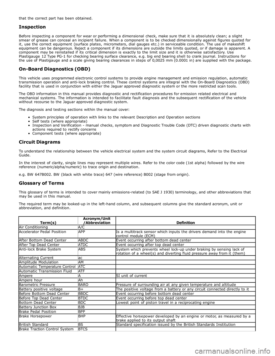
Air Conditioning A/C Accelerator Pedal Position APP
Is a multitrack sensor which inputs the drivers demand into the engine
control module (ECM) After Bottom Dead Center ABDC Event occurring after bottom dead center After Top Dead Center ATDC Event occurring after top dead center Anti-lock Brake System ABS
System which prevents wheel lock-up under braking by sensing lack of
rotation of a wheel(s) and diverting fluid pressure away from it (them) Alternating Current ac Amplitude Modulation AM Automatic Temperature Control ATC Automatic Transmission Fluid ATF Ampere A SI unit of current Ampere hour Ah Barometric Pressure BARO Pressure of surrounding air at any given temperature and altitude Battery positive voltage B+ The positive voltage from a battery or any circuit connected directly to it Before Bottom Dead Center BBDC Event occurring before bottom dead center Before Top Dead Center BTDC Event occurring before top dead center Bottom Dead Center BDC Lowest point of piston travel in a reciprocating engine Battery Junction Box BJB Brake Pedal Position BPP Brake Horsepower BHP
Effective horsepower developed by an engine or motor, as measured by a
brake applied to its output shaft British Standard BS Standard specification issued by the British Standards Institution Brake Traction Control System BTCS
Page 53 of 3039

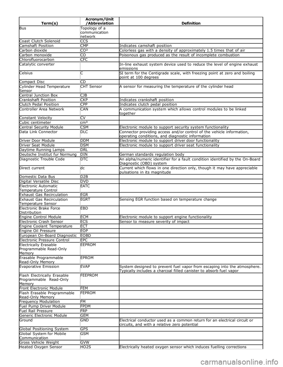
Bus Topology of a
communication
network Coast Clutch Solenoid CCS Camshaft Position CMP Indicates camshaft position Carbon dioxide CO² Colorless gas with a density of approximately 1.5 times that of air Carbon monoxide CO Poisonous gas produced as the result of incomplete combustion Chlorofluorocarbon CFC Catalytic converter
In-line exhaust system device used to reduce the level of engine exhaust
emissions Celsius C
SI term for the Centigrade scale, with freezing point at zero and boiling point at 100 degrees Compact Disc CD Cylinder Head Temperature
Sensor CHT Sensor A sensor for measuring the temperature of the cylinder head Central Junction Box CJB Crankshaft Position CKP Indicates crankshaft position Clutch Pedal Position CPP Indicates clutch pedal position Controller Area Network CAN
A communication system which allows control modules to be linked together Constant Velocity CV Cubic centimeter cm³ Central Security Module CSM Electronic module to support security system functionality Data Link Connector DLC
Connector providing access and/or control of the vehicle information, operating conditions, and diagnostic information Driver Door Module DDM Electronic module to support driver door functionality Driver Seat Module DSM Electronic module to support driver seat functionality Daytime Running Lamps DRL Deutsche Institut fur Normung DIN German standards regulation body Diagnostic Trouble Code DTC
An alpha/numeric identifier for a fault condition identified by the On-Board Diagnostic (OBD) system Direct current dc
Current which flows in one direction only, though it may have appreciable pulsations in its magnitude Domestic Data Bus D2B Digital Versatile Disc DVD Electronic Automatic Temperature Control EATC
Exhaust Gas Recirculation EGR Exhaust Gas Recirculation Temperature Sensor EGRT Sensing EGR function based on temperature change Electronic Brake Force
Distribution EBD
Engine Control Module ECM Electronic module to support engine functionality Electronic Crash Sensor ECS Sensor to measure severity of impact Engine Coolant Temperature ECT Engine Oil Pressure EOP European On-Board Diagnostic EOBD Electronic Pressure Control EPC Electrically Erasable
Programmable Read-Only Memory EEPROM
Erasable Programmable
Read-Only Memory EPROM
Evaporative Emission EVAP
System designed to prevent fuel vapor from escaping into the atmosphere. Typically includes a charcoal filled canister to absorb fuel vapor Flash Electrically Erasable
Programmable Read-Only Memory FEEPROM
Front Electronic Module FEM Flash Erasable Programmable
Read-Only Memory FEPROM
Frequency Modulation FM Fuel Pump Driver Module FPDM Fuel Rail Pressure FRP Generic Electronic Module GEM Ground GND
Electrical conductor used as a common return for an electrical circuit or
circuits, and with a relative zero potential Global Positioning System GPS Global System for Mobile
Communication GSM
Gross Vehicle Weight GVW Heated Oxygen Sensor HO2S Electrically heated oxygen sensor which induces fuelling corrections